

Page 1
TECHNOLOGY
42 Central Drive | Farmingdale NY 11735-1202
P: 631-777-5500 | F: 631-777-5599
Toll-Free: 1-800-666-4800
http://www.alphacommunications.com/
USER MANUAL
RD-GB2/A
GB2 Bus
Amplifier/
Repeater
AWD260 REV. 12/2017
Page 2
RD-GB2A BUS AMPLIFIER
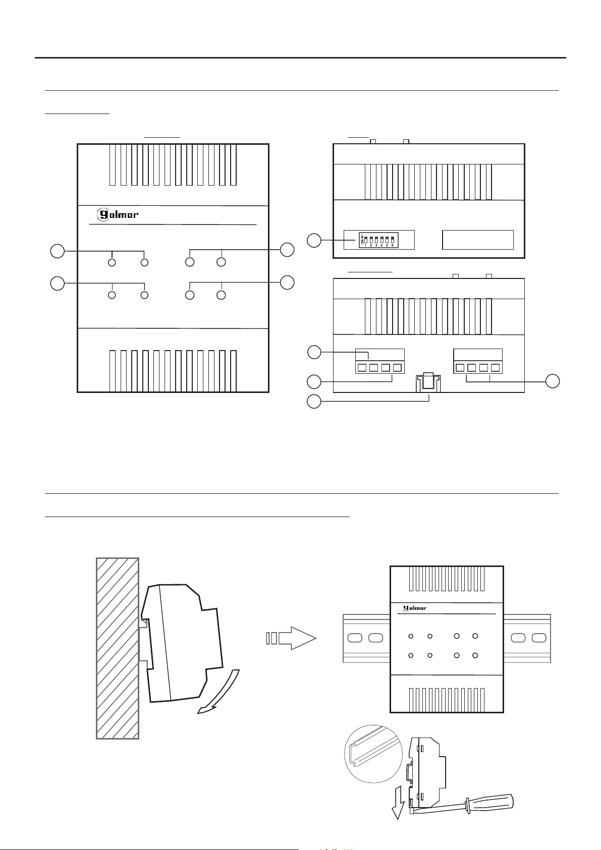
DESCRIPTION OF THE RD-GB2A BUS AMPLIFIER MODULE
Description:
FRONT TOP
2
Model: RD-GB2/A
a
Bus-IN Bus-OUT
PA PB
a
Tx/Rx In-Use
NoRoute Amp-ON
c
b
b
d
e
f
a.
Status LEDs.
b.
Configuration buttons
c.
Configuration DIP
d.
Output terminals from the amplifier to the bus.
switch.
e.
f.
g.
INSTALLATION
Illustration of RD-GB2A Bus amplifier module installation:
DIP
ON
1 2 3
4 5 6
BOTTOM
OUT DS IN IN
Interior door panel connection terminals
(general entrance door panel system).
DIN rail latch release.
Bus input terminals.
g
Install the RD-GB2A module in a dry protected location free from the risk of dripping or splashing water.
Install the RD-GB2A module with an FA-GB2A power supply.
Model: RD-GB2/A
Bus-IN Bus-OUT
Tx/Rx In-Use
PA PB
NoRoute Amp-ON
The RD-GB2A module can be mounted onto a
rail (4 elements) by applying slight pressure.
DIN
DIN 46277
To remove the RD-GB2A module from the DIN
rail, use a flat screwdriver to lever it off, as shown
in the drawing.
Page 3

RD-GB2A BUS AMPLIFIER
INSTALLATION
Description of the DIP switches:
The DIP switches of the RD-GB2A module enable configuration of one of the 3 operating modes, module address
number and end of line.
- Repeater mode enables door panel bus or monitor bus distance to be increased when it exceeds 80 m.
- Router mode enables the installation to have up to 8 risers/columns.
- Gateway mode, enables an installation withone general entrance door panel and 7 buildingswith interior doorpanels.
Configuring the operating mode:
DIP
Repeater mode:
DIP switches: 1 and 2 set to OFF.
DIP
Router mode:
DIP switches: 1 set to ON and 2 set to OFF.
DIP
Gateway mode:
DIP switches: 1 set to OFF and 2 set to ON.
DIP
No function.
( )
*
ON
1 2 3
ON
1 2 3
ON
1 2 3
ON
1 2 3
4 5 6
4 5 6
4 5 6
4 5 6
3
Configuring the address number on the RD-GB2A module installed:
DIP
( )
*
ON
1 2 3
4 5 6
To configure the RD-GB2A module as No. 1: DIP switches 3, 4 and 5 set to OFF.
( )
1
-Button panel call addresses (0 to 31) for monitor address (0 to 31) respectively.
-Coded panel call addresses (1 to 32) for monitor address (0 to 31).
Note: Call address '32' on the coded panel calls the monitor with address '0'.
DIP
ON
1 2 3
4 5 6
To configure the RD-GB2A module as No. 2: DIP switch 3 set to ON, 4 and 5 set to OFF.
( )
1
-Button panel call addresses (32 to 63) for monitor address (0 to 31) respectively.
-Coded panel call addresses (33 to 64) for monitor address (0 to 31).
Note: Call address '64' on the coded panel calls the monitor with address '0'.
DIP
ON
1 2 3
4 5 6
To configure the RD-GB2A module as No. 3: DIP switch 3 set to OFF, 4 set to ON and 5 set to OFF.
( )
1
-Button panel call addresses (64 to 95) for monitor address (0 to 31) respectively.
-Coded panel call addresses (65 to 96) for monitor address (0 to 31).
Note: Call address '96' on the coded panel calls the monitor with address '0'.
DIP
ON
1 2 3
4 5 6
To configure the RD-GB2A module as No. 4: DIP switches 3 and 4 set to ON and 5 set to OFF.
( )
1
-Button panel call addresses (96 to 127) for monitor address (0 to 31) respectively.
-Coded panel call addresses (97 to 128) for monitor address (0 to 31).
Note: Call address '128' on the coded panel calls the monitor with address '0'.
DIP
ON
1 2 3
4 5 6
To configure the RD-GB2A module as No. 5: DIP switches 3 and 4 set to OFF and 5 set to ON.
( )
1
-Coded panel call addresses (129 to 160) for monitor address (0 to 31).
Note: Call address '160' on the coded panel calls the monitor with address '0'.
DIP
ON
1 2 3
4 5 6
To configure the RD-GB2A module as No. 6: DIP switch 3 set to ON, 4 set to OFF and 5 set to ON.
( )
1
-Coded panel call addresses (161 to 192) for monitor address (0 to 31).
Note: Call address '192' on the coded panel calls the monitor with address '0'.
DIP
ON
1 2 3
4 5 6
To configure the RD-GB2A module as No. 7: DIP switch 3 set to OFF, 4 and 5 set to ON.
( )
1
-Coded panel call addresses (193 to 224) for monitor address (0 to 31).
Note: Call address '224' on the coded panel calls the monitor with address '0'.
DIP
ON
1 2 3
4 5 6
To configure the RD-GB2A module as No. 8: DIP switches: 3, 4 and 5 set to ON.
( )
1
-Coded panel call addresses (225 to 256) for monitor address (0 to 31).
Note: Call address '256' on the coded panel calls the monitor with address '0'.
IMPORTANT:
- Select a different address number for each RD-GB2Amodule.
( )
1
- Each address number of the RD-GB2A has 32 different door panel call addresses assigned for each RD-GB2A
module
( )
Factory setting.
*
addressed. For further details see pages 11-16.
Continued overleaf
Page 4
RD-GB2A BUS AMPLIFIER
IN IN
IN IN
Model: RD-GB2/A
Bus-IN Bus-OUT
Tx/Rx In-Use NoRoute
Model: RD-GB2/A
Bus-IN Bus-OUT
Tx/Rx In-Use NoRoute
NoRoute Amp-ON
INSTALLATION
Continued from previous page.
Configuring the end of line on the RD-GB2A module:
DIP
To configure the end of line of the RD-GB2A module:
ON
1 2 3
4 5 6
( )
ON
1 2 3
*
( )
Factory setting.
*
4 5 6
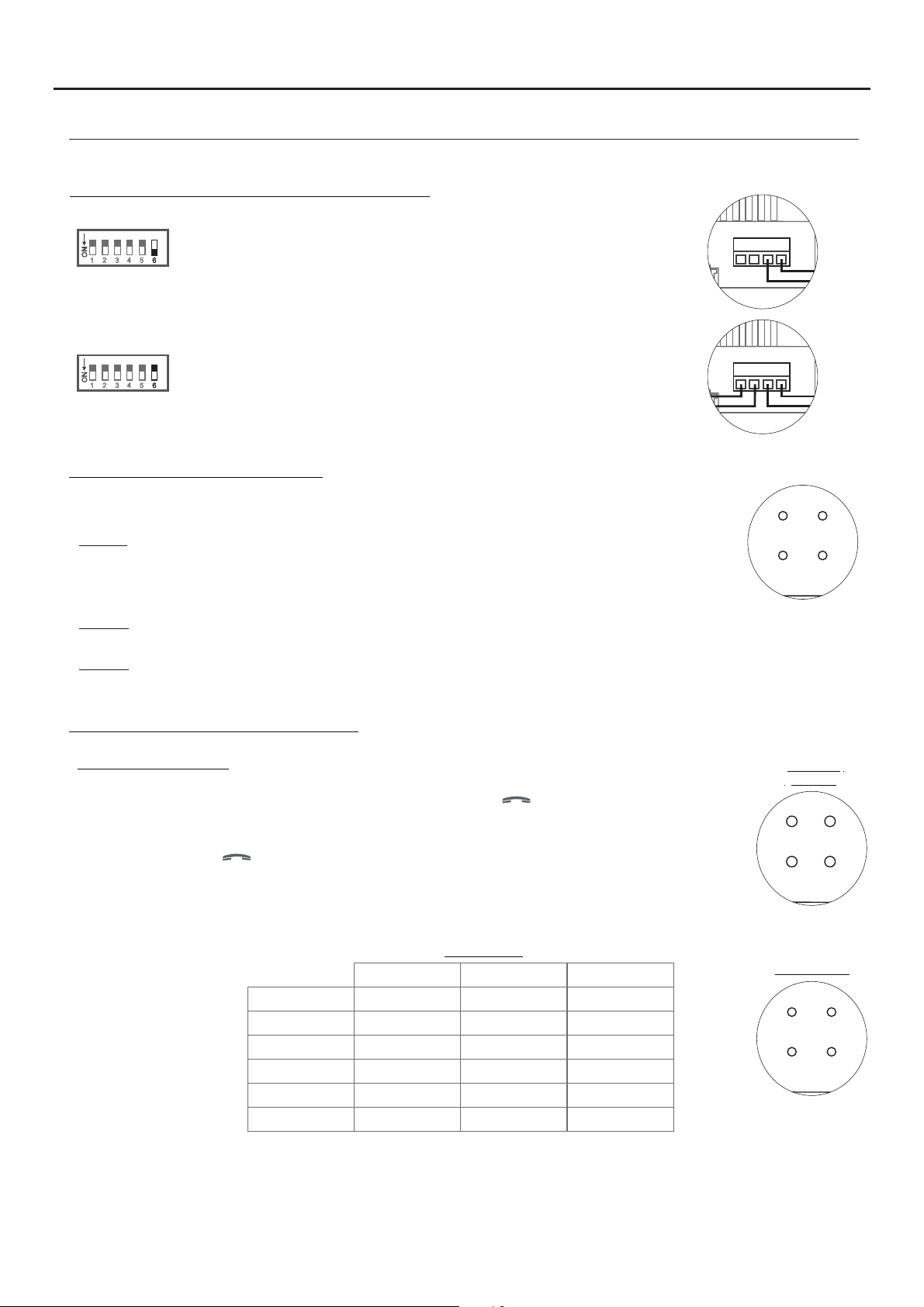
Description of the status LEDs:
The RD-GB2A module has the following status LEDs:
DIP switch 6: Set the RD-GB2A module where the Bus cable ends
(marked as 'IN' on the terminals) to ON.
DIP
To configure the end of line of the RD-GB2A module:
DIP switch 6: Leave the intermediate modules in the OFF position.
4
Bus In:
LED on: When the bus cable is connected to the 'IN' terminal.
Bus-Out:
LED on: When the monitor bus of the RD-GB2A module is connected.
TX/RX:
LED blinking: When the door panel is in communication with an RD-GB2A module monitor.
In-Use:
LED off: When the RD-GB2A module is in standby.
Description of the function buttons:
Displaying video gain:
To see the level of gain of the RD-GB2A module, press button on one of the monitors
connected to the RD-GB2A module to be displayed (the image of the door panel will be displayed
on the monitor). Note: The image should be displayed throughout the process.
Step 1: Press button on one of the monitors connected to the RD-GB2A module that requires
video gain adjustment; the 'In-Use' LED will illuminate.
Step 2: Press the 'NoRoute' button to show, through the status LEDs, the level of gain of the RD-GB2A
module; see table:
Video gain
Bus-IN LED Bus-OUT LED Tx/Rx LED
( )
*
Gai 1n
Gai 2n
Gai 3n
Gai 4n
Gai 5n
Gai 6n
ON OFF OFF
OFF ON OFF
ON ON OFF
OFF OFF ON
ON OFF ON
OFF ON ON
Function
buttons
Status LEDS
Note: Gain level from 1 to 6, with 1 the minimum value and 6 the maximum.
( )
Factory setting.
*
Continued overleaf
Page 5

RD-GB2A BUS AMPLIFIER
NoRoute Amp-ON
Model: RD-GB2/A
Bus-IN Bus-OUT
Tx/Rx In-Use NoRoute
INSTALLATION
Continued from previous page.
Adjusting video gain:
To adjust the gain of the RD-GB2A module, press button on one of the monitors connected to the RD-GB2A
module to be displayed (the image of the door panel will be displayed on the monitor). Note: The image should be
displayed throughout the process.
.
Step 1: Press button on one of the monitors connected to the RD-GB2A module that requires video gain
adjustment; the 'In-Use' LED will illuminate. (Note: RD-GB2Ain gateway mode, establish communication with
the general entrance door panel).
Step 2: Press button PA or PB to reduce or increase the gain level of the RD-GB2A module respectively. The status
LEDs will indicate the modified gain level; see table:
Video gain
Bus-IN LED Bus-OUT LED Tx/Rx LED
( )
*
Ga n 1i
Ga n 2i
Ga n 3i
Ga n 4i
Ga n 5i
Ga n 6i
ON OFF OFF
OFF ON OFF
ON ON OFF
OFF OFF ON
ON OFF ON
OFF ON ON
5
Note: Gain level from 1 to 6, with 1 the minimum value and 6 the maximum.
( )
Factory setting.
*
Step 3: Then, to save the selected gain value, press the 'NoRoute' button for 3 seconds; the 'In-Use' LED will blink.
Step 4: Press the 'NoRoute' button again for 3 seconds until the LED illuminates. This indicates that the RD-GB2A
module is operating with the gain value set in the previous steps in 'fixed mode' (always).
Step 5: Check that the new gain value is correct. With the monitor video activated, press the 'NoRoute' button and check
the status LEDs indicate the required gain value (see video gain table in step 2).
that
Note: Repeat the procedure (steps 1 to 5) until the RD-GB2Amodule is set to the required video gain
Set the video gain to 'fixed' or 'automatic' mode:
The RD-GB2A module has 2 operating modes for setting gain:
Function
'Fixed' mode: The RD-GB2A module will always use the gain configured in the module.
Step 1: Press button on one of the monitors connected to the RD-GB2A module that requires
video gain adjustment; the 'In-Use' LED will illuminate. (Note: RD-GB2A in gateway mode,
establish communication with the general entrance door panel).
Step 2: Then press the 'NoRoute'button for 3 secondsand repeat this stepuntil the 'In-Use' statusLED
illuminates.
'Automatic' mode: The RD-GB2A module adjusts the gain automatically when it connects to the
system.
Step 1: Press button on one of the monitors connected to the RD-GB2A module that requires
adjustment to 'automatic' mode; the 'In-Use' LED will illuminate.
buttons
Status LEDS
Step 2: Then press the 'NoRoute'button for 3 secondsand repeat this stepuntil the 'In-Use' statusLED
Default settings:
To use the default settings of the RD-GB2A module (level 1 gain and 'fixed' mode):
Step 1: Disconnect the module from the power supply.
Step 2: Reconnect the module to the power supply. Then, during the first 10 seconds, with the RD-GB2A
is blinking.
module
confirming that the module is now using the default settings.
in standby, press the 'NoRoute' button for 3 seconds; the 'In-Use' status LED will blink once
Page 6

RD-GB2A BUS AMPLIFIER
WIRING DIAGRAMS:
Installation of a video door entry system with RD-GB2A 'router' mode (enables up to 8 risers/verticals).
6
(1)
BUS BUS
(1)
BUS BUS
100~240Vac
( )
End of
*
ON
D2L-GB2
End of
OFF
D2L- 2GB
Mains
N L
L
line
line
D2D1
BUS BUS
D2D1
BUS BUS
VESTA2
Master
BUS
VESTA2
Master
BUS
VESTA2
Master
BUS
CN
FA- 2GB /A
BUS (M) BUS(PL)
APARTMENT 23
APARTMENT 2
APARTMENT 1
( )3
( )3
( )
( )
( )3**( )
( )3**( )
( )3**( )( )3**( )
**
**
Stairway 1Stairway 8
(1)
BUS BUS
(1)
BUS BUS
100~240Vac
( )
End of
*
ON
D2L-GB2
End of
OFF
D2L- 2GB
Mains
N L
L
line
D2D1
line
D2D1
BUS BUS
BUS BUS
VESTA2
Master
BUS
VESTA2
Master
BUS
VESTA2
Master
BUS
CN
FA- 2GB /A
BUS (M) BUS(PL)
APARTMENT 23
APARTMENT 2
APARTMENT 1
( )3
( )3
( )3**( )
( )3**( )
( )3**( )( )3**( )
( )
( )
**
**
Nº8 Nº1
OUT
R GB AD-
DS
2
IN IN
R modeouter
( )**( )
**
OUT
R GB AD-
DS
2
IN IN
R modeouter
Access panel
Button
router mode
or
( )
Remove the jumper from all
*
of the distributors except
the last.
( )
Configure the end of line on
**
the last monitor/RD-GB2A.
DIP 6 to ON.
Important:
(1)
Leave the jumper in this position for 4,3" GB2 monitors of all of the D2L-GB2 distributors.
(2)
N/A
(3)
For description, installation, configuration and programming of the monitor and door panel, see the corresponding manual.
Coded
router mode
SW1
ON
1 2 3 4 5 6
+
12Vdc
_
NA1
C1
Relay 1
AP-
AP+
or
NA2
Relay 2
C2
Mains
100~240Vac
N L
L
( )3
Coded panelButton panel
AP+ AP-
P1 P2
CN
FA- 2GB /A
BUS (M) BUS(PL)
BUSBUS
 Loading...