

Page 1
TM
USM2.5 Status Monitoring Module
with Acterna Embedded Transponder
Technical Manual
Effective: September, 2003
Alpha T echnologies
®
Page 2

Alpha Technologies
Power
®
2
018-041-C0-003 Rev. C
Page 3

™
USM2.5 Status Monitoring Module
with Acterna Embedded T ransponder
T echnical Manual
018-041-C0-003 Rev. C — © 2003 by Alpha Technologies, Inc.
Effective: September 2003
Statement of Intended Usage
Alpha denies responsibility for any damage or injury involving its enclosures, power
supplies, generators, batteries, or other hardware when used for an unintended
purpose, installed or operated in an unapproved manner , or improperly maintained.
Information on CE Compliance
Alpha T echnologies Communications Module, model USM 2.5, has been qualified as an
EMC Class B product, when configured in an Alpha Uninterruptible Power Supply (UPS)
product. When an (optional) Acterna Embedded T ransponder Assembly is configured in
an Alpha UPS with model USM 2.5 Communications Module, the result ant UPS product
configuration complies only to Class A requirements, in accordance with the EMC
Directive and applicable T echnical S tandards.
Contacting Alpha Technologies:
For general product information and customer service
1-800-863-3930
(7:00 AM to 5:00 PM Pacific Time )
For complete technical support
1-800-863-3364
(7:00 AM to 5:00 PM Pacific Time, or 24/7 emergency support)
018-041-C0-003 Rev. C
3
Page 4

Table of Contents
Safety.................................................................................................5
1. Installation .....................................................................................9
1.1 Installation in an XM Series 2 Power Supply..........................................9
1.2 Transponder Inputs and Outputs.......................................................... 11
1.3 Battery Monitor Connections ............................................................... 12
1.4 Generator Connection .........................................................................19
1.5 Generator Ignition Battery Connection ................................................. 20
1.6 COMM and RF Connections................................................................21
2. Specifications..............................................................................22
2.1 Channel Parameters............................................................................ 22
3. Troubleshooting ..........................................................................23
3.1 Important Troubleshooting Notes .........................................................23
3.2 T roubleshooting Specifics and T esting .................................................25
4. Part Numbers..............................................................................26
4.1 Cable Kit Options ................................................................................ 26
List of Tab les and Figures
Figure 1-1 Transponder Installation.......................................................................................10
Figure 1-2 Input / Output Connections .................................................................................. 11
Figure 1-3 Battery Monitor Connections for three 48Vdc battery packs ................................12
Figure 1-4 Battery Monitor Connections for two 48Vdc battery packs...................................13
Figure 1-5 Battery Monitor Connections for one 48Vdc battery pack ....................................14
Figure 1-6 Battery Monitor Connections for one 36Vdc battery pack ....................................15
Figure 1-7 Battery Monitor Connections for two 36Vdc battery packs...................................16
Figure 1-8 Battery Monitor Connections for three 36Vdc battery packs ................................17
Figure 1-9 Battery Monitor Connections for four 36Vdc battery packs ..................................18
Figure 1-10 Generator Monitor Connections ...........................................................................19
Figure 1-11 Generator Ignition Battery Connection .................................................................20
Figure 1-12 COMM / RF Connections ....................................................................................21
Figure 3-1 Battery String Example........................................................................................24
T ab le 2-1 Channel Parameters............................................................................................22
Table 4-1 Cable kit part numbers ........................................................................................26
4
018-041-C0-003 Rev. C
Page 5
Safety
Safety Notes
This symbol identifies conditions and actions that pose a hazard to the user.
This symbol cautions the user of conditions and actions that may damage the
powersupply or associated equipment.
This symbol identifies a condition that may be corrosive to equipment and parts,
or damaging to skin.
This symbol identifies a condition in which it is required to recycle discarded
materials.
This symbol identifies a situation in which static-sensitive components are present.
Warnings
WARNING: This power supply and its associated hardware (enclosure, batteries,
cabling) may contain equipment, batteries or parts which have accessible
hazardous voltage or currents.
T o av oid injury
:
• This power supply and its associated hardware must be serviced by authorized
personnel only .
• The enclosure which contains the power supply and associated equipment must remain
locked at all times, except when authorized service personnel are present.
• Remove watch and/or jewelry prior to servicing equipment, parts, connectors, wiring, or
batteries.
• Read and follow all installation, equipment grounding, usage, and service instructions
included in this manual.
• Use proper lifting techniques whenever handling equipment, parts, or batteries.
• Batteries contain dangerous voltages, currents and corrosive material. Battery
installation, maintenance, service and replacement must be performed by authorized
personnel only .
• Never use uninsulated tools or other conductive materials when installing, maintaining,
servicing or replacing batteries.
• Use special caution when connecting or adjusting battery cabling. An improperly
connected battery cable or an unconnected battery cable can result in arcing, a fire, or
possible explosion.
• A battery that shows signs of cracking, leaking or swelling must be replaced immediately
by authorized personnel using a battery of identical type and rating.
018-041-C0-003 Rev. C
5
Page 6

Safety
Warnings,
continued
• Avoid any contact with gelled or liquid emissions from a valve-regulated lead-acid
(VRLA) battery . Emissions contain dilute sulfuric acid which is harmful to the skin and
eyes. Emissions are electrolytic, which are electrically conductive and are corrosive.
Follow the Chemical Hazards notes if contact occurs.
• Do not smoke or introduce sparks in the vicinity of a battery .
• Under certain overcharging conditions, lead-acid batteries can vent a mixture of
hydrogen gas which is explosive. Proper venting of the enclosure is required.
• Follow the battery manufacturer’s approved transportation and storage instructions.
Cautions
NOTE: Equipment or parts may be damaged or cause damage if used or
installed improperly .
T o a void damage
:
• Prior to installation, verify that the AC input voltage to the enclosure and its equipment
match with respect to voltage and frequency .
• Prior to installation, verify that the output voltage from the enclosure or its equipment
match the voltage requirements of the connected equipment (load).
• Prior to installation, verify that the enclosure’s utility service panel is equipped with a
properly rated circuit breaker for use with the equipment inside. Refer to manufacturer’s
recommendations.
• Review and upgrade utility service panel circuit breaker requirements whenever the
equipment within the enclosure is changed.
• Prior to installation, contact local utilities, local building maintenance departments, and
cable/piping locator services to ensure that installation does not interfere with existing
utility or building cables/piping.
• Do not exceed the output rating of equipment. V erify load requirements prior and during
connection process.
• Prior to handling the batteries, touch a grounded metal object to dissipate any static
charge that may hav e dev eloped in your body.
The circuit board contains static-sensitive components. Please follow all appropriate
ESD (Electro Static Discharge) handling practices. As an extr a precaution, handle the
USM2.5 with Acterna Embedded Transponder Module b y the edges and keep fingers awa y
from card edge connectors.
6
018-041-C0-003 Rev. C
Page 7

Battery Safety
Lead-acid batteries contain dangerous voltages, currents and corrosive material. Battery
installation, maintenance, service and replacement must be performed by authorized personnel
only.
Any gelled or liquid emissions from a V alve-Regulated lead-acid (VRLA) battery
contain dilute sulfuric acid, which is harmful to the skin and eyes. Emissions are
electrolytic, which are electrically conductive and corrosive.
Chemical Hazards
T o avoid injury:
Safety
• Wear protective clothing (insulated gloves, eye protection, etc) whenever installing,
maintaining, servicing, or replacing batteries.
• If any battery emission contacts the skin, wash immediately and thoroughly with water .
Follow your company’s approved chemical exposure procedures.
• If any battery emission contacts the eye, wash immediately and thoroughly with water for
10 minutes with pure water or a special neutralizing eye wash solution and seek
immediate medical attention. Follow your company’s approved chemical exposure
procedures.
• Neutralize any spilled battery emission with the special solution contained in an approved
spill kit or with a solution of 1 lb. bicarbonate of soda to 1 gal of water. Report chemical
spill using your company’s spill reporting structure and seek medical attention if
necessary.
• Always replace batteries with those of an identical type and rating. Never install old or
untested batteries.
• Do not charge batteries in a sealed container . Each individual battery should have at least
0.5 inches of space between it and all surrounding surfaces to allow for convection cooling.
• All battery compartments must have adequate ventilation to prevent an accumulation of
potentially dangerous gas.
018-041-C0-003 Rev. C
7
Page 8

Safety
Maintenance Guidelines
The battery maintenance instructions listed below are for reference only . Battery manufacturer’s
instructions for transportation, installation, storage or maintenance take precedence over these
instructions.
• T o prevent damage inspect batteries every 3 months for:
-Signs of battery cracking, leaking or swelling. The battery should be replaced
immediately by authorized personnel using a battery of the identical type and rating.
-Signs of battery cable damage. Battery cable should be replaced immediately by
Authorized Personnel using replacement parts specified by vendor .
-Loose battery connection hardware. Refer to battery manufacturer’s documentation
for the correct torque and connection hardware for the application.
• Apply battery manufacturer’s specified antioxidant compound on all exposed connections.
• Verify battery terminals and/or exposed connection hardware has not shif ted within 2
inches of a conductive surface. Reposition batteries as necessary to maintain adequate
clearance.
• Clean up any electrolyte (battery emission) in accordance with all federal, state, and local
regulations or codes.
Recycling and Disposal Instructions
Spent or damaged batteries are considered environment ally unsafe. Always recycle used
batteries or dispose of the batteries in accordance with all federal, state and local
regulations.
8
018-041-C0-003 Rev. C
Page 9
1.1 Installation in an XM Series 2 Power Supply
1. Record the transponder address (located on the sheet
metal of the front panel).
2. Open the power supply enclosure.
NOTE: Backup power will not be available while
batteries are disconnected.
3. Set the battery breaker on the front of the power
supply to the OFF position.
4. Unplug all connectors on the front of the power
supply inverter module.
5. Loosen the thumb screws holding the inverter
module into the power supply.
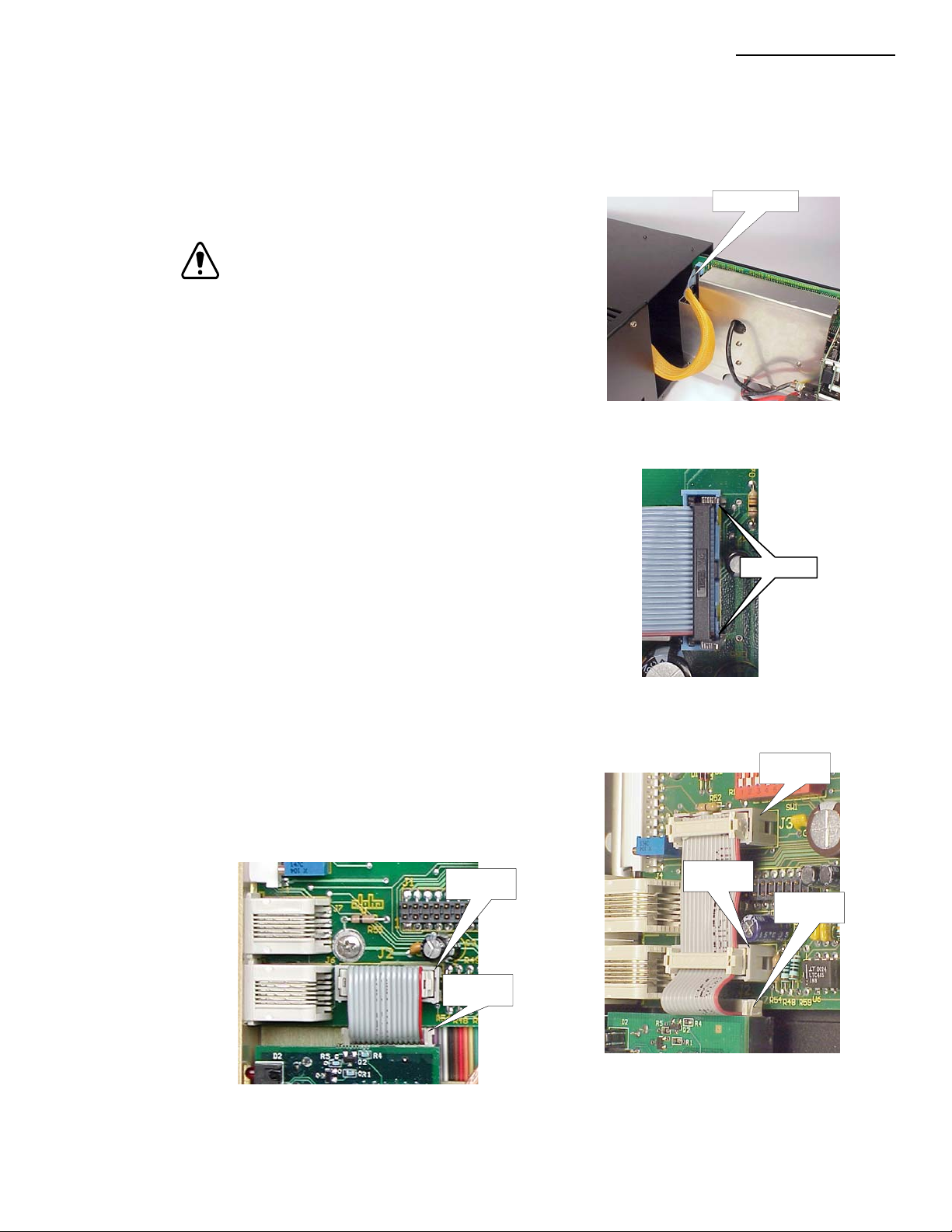
6. Slide the inverter module out far enough to unplug
the ribbon cable at the back of the inverter module
(fig A). Disengage the tw o latches holding the plug
into the socket (fig. B), and remove the plug.
1. Installation
Disconnect here
Fig. A
7. Slide the inverter module all of the way out of the
power supply .
8. Remove the blanking plate and USM2 (if installed)
from the inverter module.
9. Install the USM2.5 (refer to USM2.5 Operator's and
T echnical manual. P/N: 704-683-B0-xxx).
10(a).
For a USM2.5 with single ribbon cable socket (J2):
Attach one end of the 2-position ribbon cable to the
connector (JP2) at the top of the transponder , and
the other end to the connector on the USM2.5 (J2).
(fig. C)
J2
JP2
Unlatch
Fig. B
J3
J2
JP2
018-041-C0-003 Rev. C
Fig. D; Three-Position Ribbon Cable
Connection
Fig. C; T wo-P osition Ribbon Cable Connection
9
Page 10

1. Installation
1.1 Installation in an XM Series 2 Power Supply,
10(b).
For a USM2.5 with two ribbon cable sockets (J2, J3):
Attach one end of the 3-position ribbon cable to the connector (JP2) at the top of the
transponder, and the other tw o connectors to the USM2.5 (J2, J3). (fig. D)
8 Position DIP
Switch
Captive
screw
10 Position
Jumper
Captive
screw
continued
Figure 1-1 Transponder Installed
11. Using the two captive screws just behind the face plate, secure the transponder
to the inverter module.
12. Verify that the 10-position jumper on the transponder is set to the correct
battery pack voltage.
13. Verify that the 8-position DIP Switch on the USM2.5 is set correctly. Ref er to the USM2.5
operators manual (Alpha p/n 704-683-B0).
14. Set the inverter module onto the guides, and slide it 1 or 2 inches into the power supply.
15. Reconnect the ribbon cable to the inverter module, and latch the two retaining
clips over the ribbon cable plug.
16. Slide the inverter module fully into the power supply , and tighten the thumb
screws. Set the BATTERY BREAKER to the ON position.
17. Verify after 10-30 seconds, the Smart Display on the power supply reads
'OPERA TION NORMAL'.
18. Download Alarm Profile from CheetahNet to initiate appropriate mode of operation.
10
19. Verify that, after approx. 1 minute , the 'CPU' LED on the front of the transponder
is blinking, if not, press the RESET button behind the hole next to the LEDs
(see fig. 1-2).
018-041-C0-003 Rev. C
Page 11

1. Installation
1.2 Transponder Inputs and Outputs
The following section describes the input and output connections on the transponder. Refer to
the sections indicated below for a brief description and pin-out of the connector .
CPU LED Flashing: Normal operation, P-Code running.
Solid: Initial start-up, R-Code running.
RX LE D Data is being received from the HEC (Head End Controller).
TX LED Data is being sent to the HEC.
CPU
RESET
CPU / Seria l P ort
Activity
Section 1.3
Battery A/B Monitor
Section 1.3
Battery C/D Monitor
Section 1.6
Craft Port
A/B
C/D
COM
RX TX
1
1
G/BATT
TEMP
GEN
1
1
Section 1.4
Generator
Section 1.5
Generator Battery
Section 1.6
RF
Communication
018-041-C0-003 Rev. C
Figure 1-2 Input / Output Connections
11
Page 12

1. Installation
1.3 Battery Monitor Connections
WARNING: V erify that the 10 P osition jumper on the tr ansponder is set to
NOTE: A maximum of 12 batteries can be monitored by the transponder .
Connector Pin # String Reference Wire Label CheetahNet Display (48V)
A/B 1 1A - (0Vdc) A/B[C/D] NEG
C/ D 1 1C - (0Vdc) A/B[C/D] NEG
Refer to section 4 for wire kit part numbers.
the proper battery voltage prior to connecting the battery monitor
wire kit.
2 1A + (+12Vdc) Vbatt 1A [C] 12V Battery #4 Vdc
3 2A + (+24Vdc) Vbatt 2A [C] 24V Battery #3 Vdc
4 3A + (+36Vdc) Vbatt 3A [C] 36V Battery #2 Vdc
5 1B + (+12Vdc) Vbatt 1B [D] 12V Battery #8 Vdc
6 2B + (+24Vdc) Vbatt 2B [D] 24V Battery #7 Vdc
7 3B + (+36Vdc) Vbatt 3B [D] 36V Battery #6 Vdc
4A + (+48Vdc) Battery #1 Vdc
8 4B + (+48Vdc) Vbatt A/B [C/D] 48V Battery #5 Vdc
2 1C + (+12Vdc) Vbatt 1A [C] 12V Battery #11 Vdc
3 2C + (+24Vdc) Vbatt 2A [C] 24V Battery #10 Vdc
4 3C + (+36Vdc) Vbatt 3A [C] 36V Battery #9 Vdc
5
6
7
8 4C + (+48Vdc) Vbatt A/B [C/D] 48V Battery #12 Vdc
NOTE: Only TW O 48V strings can be monitored when using a generator .
DO NOT connect to the BATT C/D connector if using the generator option.
Battery Monitored
Via Pin 8
12V
24V
36V
48V
Battery String A
A/B
8
4
7
3
6
2
1
5
1A
12V
2A
24V
3A
36V
4A
48V
To Power Supply
Battery String B
12V
1B
24V
2B
36V
3B
48V
4B
Battery String C
C/D
1C
2C
3C
4C
4
8
3
7
6
2
1
5
12
Figure 1-3 Battery Monitor Connections for three 48Vdc battery packs
018-041-C0-003 Rev. C
Page 13

1. Installation
1.3 Battery Monitor Connections
, continued
Connector Pin # String Reference Wire Label CheetahNet Display (48V)
A/B 1 1A - (0Vdc) A/B[C/D] NEG
2 1A + (+12Vdc) Vbatt 1A [C] 12V Battery #4 Vdc
3 2A + (+24Vdc) Vbatt 2A [C] 24V Battery #3 Vdc
4 3A + (+36Vdc) Vbatt 3A [C] 36V Battery #2 Vdc
5 1B + (+12Vdc) Vbatt 1B [D] 12V Battery #8 Vdc
6 2B + (+24Vdc) Vbatt 2B [D] 24V Battery #7 Vdc
7 3B + (+36Vdc) Vbatt 3B [D] 36V Battery #6 Vdc
4A + (+48Vdc) Battery #1 Vdc
8 4B + (+48Vdc) Vbatt A/B [C/D] 48V Battery #5 Vdc
Battery Monitored
Via Pin 8
12V
24V
36V
48V
Battery String A
A/B
8
4
7
3
6
2
1
5
1A
12V
2A
24V
3A
36V
4A
48V
To Power Supply
Battery String B
1B
2B
3B
4B
C/D
4
8
3
7
6
2
1
5
Not used in this configuration
018-041-C0-003 Rev. C
Figure 1-4 Battery Monitor Connections for two 48Vdc battery packs
13
Page 14

1. Installation
1.3 Battery Monitor Connections
, continued
Connector Pin # String Reference Wire Label CheetahNet Display (48V)
A/B 1 1A - (0Vdc) A/B[C/D] NEG
2 1A + (+12Vdc) Vbatt 1A [C] 12V Battery #4 Vdc
3 2A + (+24Vdc) Vbatt 2A [C] 24V Battery #3 Vdc
4 3A + (+36Vdc) Vbatt 3A [C] 36V Battery #2 Vdc
5
6
7
8 4A + (+48Vdc) Vbatt A/B [C/D] 48V Battery #1 Vdc
A/B
C/D
12V
24V
36V
48V
Battery String A
3487
2
6
5
1
1A
2A
3A
4A
To Power Supply
Not used in this configuration
3487
2
1
6
5
Figure 1-5 Battery Monitor Connections for one 48Vdc battery pack
14
018-041-C0-003 Rev. C
Page 15

1. Installation
1.3 Battery Monitor Connections, continued
Connector Pin # String Reference Wire Label CheetahNet Display (36V)
A/B 1 1A - (0Vdc) A/B[C/D] NEG
2 1A + (+12Vdc) Vbatt 1A [C] 12V Battery #3 Vdc
3 2A + (+24Vdc) Vbatt 2A [C] 24V Battery #2 Vdc
4 3A + (+36Vdc) Vbatt 3A [C] 36V Battery #1 Vdc
5
6
7
8
12
V
24
V
36
V
Battery String A
A/B
3487
2
6
1
5
1A
2A
3A
To Power Supply
C/D
3487
2
6
1
5
Not used in this configuration
018-041-C0-003 Rev. C
Figure 1-6 Battery Monitor Connections for one 36Vdc battery pack.
15
Page 16

1. Installation
1.3 Battery Monitor Connections
, continued
Connector Pin # String Reference Wire Label CheetahNet Display (36V)
A/B 1 1A - (0Vdc) A/B[C/D] NEG
2 1A + (+12Vdc) Vbatt 1A [C] 12V Battery #3 Vdc
3 2A + (+24Vdc) Vbatt 2A [C] 24V Battery #2 Vdc
4 3A + (+36Vdc) Vbatt 3A [C] 36V Battery #1 Vdc
5 1B + (+12Vdc) Vbatt 1B [D] 12V Battery #6 Vdc
6 2B + (+24Vdc) Vbatt 2B [D] 24V Battery #5 Vdc
7 3B + (+36Vdc) Vbatt 3B [D] 36V Battery #4 Vdc
8
A/B
4
8
3
7
6
2
1
5
12V
1A
24V
2A
36V
3A
Battery String A Battery String B
To Power Supply
12V
24V
36V
1B
2B
3B
C/D
4
8
3
7
6
2
1
5
Not used in this configuration
16
Figure 1-7 Battery Monitor Connections for two 36Vdc battery packs
018-041-C0-003 Rev. C
Page 17

1. Installation
1.3 Battery Monitor Connections
, continued
Connector Pin # String Reference Wire Label CheetahNet Display (36V)
A/B 1 1A - (0Vdc) A/B[C/D] NEG
2 1A + (+12Vdc) Vbatt 1A [C] 12V Battery #3 Vdc
3 2A + (+24Vdc) Vbatt 2A [C] 24V Battery #2 Vdc
4 3A + (+36Vdc) Vbatt 3A [C] 36V Battery #1 Vdc
5 1B + (+12Vdc) Vbatt 1B [D] 12V Battery #6 Vdc
6 2B + (+24Vdc) Vbatt 2B [D] 24V Battery #5 Vdc
7 3B + (+36Vdc) Vbatt 3B [D] 36V Battery #4 Vdc
8
C/ D 1 1C - (0Vdc) A/B[C/D] NEG
2 1C + (+12Vdc) Vbatt 1A [C] 12V Battery #9 Vdc
3 2C + (+24Vdc) Vbatt 2A [C] 24V Battery #8 Vdc
4 3C + (+36Vdc) Vbatt 3A [C] 36V Battery #7 Vdc
5
6
7
8
A/B
C/D
4
8
3
7
6
2
1
5
12V
24V
36V
Batte ry S trin g A
1A
2A
3A
To Power Supply
12V
24V
36V
Batte ry S trin g B
1B
2B
3B
12V
24V
36V
Batte ry S trin g C
1C
2C
3C
Figure 1-8 Battery Monitor Connections for three 36Vdc battery packs
4
8
3
7
6
2
1
5
018-041-C0-003 Rev. C
17
Page 18

1. Installation
1.3 Battery Monitor Connections
, continued
Connector Pin # String Reference Wire Label CheetahNet Display (36V)
A/B 1 1A - (0Vdc) A/B[C/D] NEG
2 1A + (+12Vdc) Vbatt 1A [C] 12V Battery #3 Vdc
3 2A + (+24Vdc) Vbatt 2A [C] 24V Battery #2 Vdc
4 3A + (+36Vdc) Vbatt 3A [C] 36V Battery #1 Vdc
5 1B + (+12Vdc) Vbatt 1B [D] 12V Battery #6 Vdc
6 2B + (+24Vdc) Vbatt 2B [D] 24V Battery #5 Vdc
7 3B + (+36Vdc) Vbatt 3B [D] 36V Battery #4 Vdc
8
C/ D 1 1C - (0Vdc) A/B[C/D] NEG
2 1C + (+12Vdc) Vbatt 1A [C] 12V Battery #9 Vdc
3 2C + (+24Vdc) Vbatt 2A [C] 24V Battery #8 Vdc
4 3C + (+36Vdc) Vbatt 3A [C] 36V Battery #7 Vdc
5 1D + (+12Vdc) Vbatt 1A [D] 12V Battery #12 Vdc
6 1D + (+12Vdc) Vbatt 2A [D] 24V Battery #11 Vdc
7 1D + (+12Vdc) Vbatt 3A [D] 12V Battery #10 Vdc
8
NOTE: Only THREE 36V strings can be monitored when
using a generator. DO NO T connect a f ourth string
to the BATT C/D connector if using the generator option.
12V
24V
36V
Battery String A
1A
2A
3A
To Power Supply
A/B
4
8
3
7
6
2
1
5
12V
24V
36V
Battery String B
1B
2B
3B
12V
24V
36V
Battery String C Battery String D
1C
2C
3C
C/D
8
4
7
3
6
2
1
5
Figure 1-9 Battery Monitor Connections for four 36Vdc battery packs
12V
24V
36V
1D
2D
3D
18
018-041-C0-003 Rev. C
Page 19

1. Installation
1.4 Generator Connection
The Generator Connector provides the Transponder with alarms and status signals. Control
signals can also be sent to the generator for test and Run / Stop. Refer to the ECM operation
and maintenance manual for further information on the generator connections.
PIN # Generator connection
1 APU Fail / Major Alarm
2 APU Minor Alarm
3 Engine Alarm
4 Gas Hazard Alarm
5 APU T est Fail Alarm
6 APU Enclosure Alarm
7 Engine Status
8 APU Enclosure Tamper
9 APU Signal Return / ground
1 0 APU Run / Test Command
11 Run / T est Command Return
12 No Connection
Battery
Breaker
Battery
Output 1LRI
Input
Temp
Probe
Figure 1-10 Generator monitor connections
Wire Entry
View
612
511
410
39
28
17
Alpha P/N 874-975-20
Wire Entry
View
159
2610
3711
4812
To Generator
Compartment
018-041-C0-003 Rev. C
19
Page 20

1. Installation
1.5 Generator Ignition Battery Connection
The Generator Battery Connector provides the transponder with voltage information on the
Ignition Battery and optional ambient temperature probe.
PIN # Generator Connection
1 Ignition Battery Negative / Chassis Ground
2 Ignition Battery Positive
3 External T emperature Probe
4 Ignition Battery Negative / Chassis Ground
Battery
Breaker
Battery
Output 1LRI
Input
Temp
Probe
Optional External
Temp Probe
Figure 1-11 Generator Ignition battery connection
Wire Entry
View
2
4
1
3
Alpha P/N 874-976-20
Wire Entry
To Generator
Compartment
View
External T emp Probe
2
Chassis Gro u nd
1
Alpha P/N 745-178-20
Wire Entry
View
2
1
Ignition Pos.
Ignition Neg.
20
018-041-C0-003 Rev. C
Page 21

1. Installation
1.6 COMM and RF Connections
The COMM connector allows the technician to bypass the RF modulator and communicate
with the transponder through a PC's RS-232 serial port.
The RF connector is the primary I/O port to the head-end modem.
RF Cable
To Headend
COMM (RJ-11)
Output 1LRI
Battery
Breaker
User Provided
Ground Block
Battery
Input
Temp
Probe
User Prov ided
RF
Acterna
Provided Cable
(RJ-11 to DB9)
Acterna P/N 3200-00-4002
Laptop With
Test2Way Software
018-041-C0-003 Rev. C
See note below
Figure 1-12 COMM / RF connections
NO TE : Wire from the ground block MUST be connected to the enclosure's
grounding lug, or ground bar. Ensure that all connections are
clean and bare. Coax MUST share the same ground as the
power supply .
21
Page 22

2. Specifications
2.1 Channel Parameters
Channel
Description
Analog Inputs Internal Temperature (C) 0 10 50 60
Analog Inputs
Analog Inputs AC Output Curre nt 1 (AMPS) 0.5 2 25 25.5
Analog Inputs AC Output Curre nt 2 (AMPS) 0.5 2 25 25.5
Analog Inputs Battery Voltage #1 (VDC) 10 11 14.4 14.8
Analog Inputs Battery Voltage #2 (VDC) 10 11 14.4 14.8
Analog Inputs Battery Voltage #3 (VDC) 10 11 14.4 14.8
Analog Inputs Battery Voltage #4 (VDC) 10 11 14.4 14.8
Analog Inputs Battery Voltage #5 (VDC) 10 11 14.4 14.8
Analog Inputs Battery Voltage #6 (VDC) 10 11 14.4 14.8
Analog Inputs Battery Voltage #7 (VDC) 10 11 14.4 14.8
Analog Inputs Battery Voltage #8 (VDC) 10 11 14.4 14.8
Analog Inputs Battery Voltage #9 (VDC) 10 11 14.4 14.8
Analog Inputs Battery Voltage #10 (VDC) 10 11 14.4 14.8
Analog Inputs Battery Voltage #11 (VDC) 10 11 14.4 14.8
Analog Inputs Battery Voltage #12 (VDC) 10 11 14.4 14.8
Analog Inputs Generator Battery (VDC) 10 11 14.4 14.8
Analog Inputs AC Output Voltage (VAC) 50 55 95 98
Analog Inputs AC Input Voltage (VAC) 95 100 125 128 2
Analog Inputs AC Input Voltage (VAC) 200 210 245 255 4
Digital input Standby Mode Normal Standby
Digital input Tamper Switch Open Closed
Digital input Output Fail Alarm Normal Alarm
Digital input General Alarm Normal Alarm 1
Digital input APU Test Fail Alarm Normal 1
Digital input Engine Status OFF ON 1
Digital input APU Fail / ECM Alarm Normal 1
Digital input APU Response Alarm Normal 1
Digital input Gas Hazard Alarm Alarm Normal 1
Digital input APU Engine Alarm Alarm Normal 1
Digital input Generator Enclosure Open Closed 1
Digital input Generator Tamper Closed Open 1
Digital output Standby ON / OFF OFF ON
Digital output Equalize ON / OFF OFF ON
Digital output Engine ON / OFF OFF ON
Note 1 - Generator
Note 2 - AC Input 120 VAC Models
Note 3 - External Temperature
Note 4 - AC Input 240 VAC Models
Paramete r na me Units Maj Low Min Low Min Hi Maj Hi Note
External
Temperature
(C) 0 10 50 60 3
Hi State Lo State
22
T ab le 2-1 Channel Parameters
018-041-C0-003 Rev. C
Page 23

3. Troubleshooting
3.1 Important Troubleshooting Notes
Always troubleshoot communication problems before working on battery-related and/or generatorrelated problems. The embedded transponder runs off of the power supply’s USM2.5 logic voltages,
and does not require the sensing cables (from the batteries or the generator) to communicate.
1.
USM2.5 Switch Set-up: The 8 position “DIP” switch on the USM2.5 board must be set correctly .
See the complete chart in the USM2.5 Status Monitor Operator’s and T echnical Manual P/N
704-683-B0-xxx. Note that SW1-4 (the fourth switch from the front) must be turned ON when
using an internal Acterna transponder .
USM2.5 Switch Settings for Embedded Acterna T ransponders
XM2 Models
all XM2 -610 & -615; all XM2-910 &
-915; XM2-1350 @ 75VAC or 90VAC
XM2-1350 @ 60VAC
XM2-1350-48 @ 75VAC or 90VAC
XM2-1350-48 @ 60VAC; all XM2-922
SW1SW2SW3SW4SW5SW6SW
ON ON
ON ON ON
off off off off off off
off off off off off
off off off off
ON ON
off off off
ON ON
ON ON
ON ON
ON
SW
8
7
2. Transponder Address: The transponder address is the five (5) digit number printed on the sticker
on the FRONT of the Embedded T ransponder Assembly , above the “F” connector . The address
is not the printed circuit board serial number (typically in the format of 1B followed by six
numbers) from the sticker on the PCB itself. The address can be verified from the SOC (Sys-
tems Operation Center).
3. Transponder Driver: The correct Acterna device driver must be downloaded from the HEC to the
transponder. The following is Acterna’ s list of device drivers for embedded (internal) transponders
in Alpha T echnologies XM2 power supplies, as of 17 October 2002.
Acterna Battery Input / Utility Power
Driver # Voltage Battery Monitoring Voltage Generator Supply
8028 36VDC 4 battery strings max 120VAC none single
8029 36VDC 3 battery strings max 120VAC w ith generator single
8030 48VDC 3 battery strings max 120VAC none single
8031 48VDC 2 battery strings max 120VAC w ith generator single
8033 36VDC 4 battery strings max 240VAC none single
8034 36VDC 3 battery strings max 240VAC w ith generator single
8035 48VDC 3 battery strings max 240VAC none single
8036 48VDC 2 battery strings max 240VAC w ith generator single
8037 48VDC 1 battery strings max 240VAC w ith generator dual
018-041-C0-003 Rev. C
For technical support for cable products, contact Tollgrade at:
T ollgrade Communications, Inc.
7020 Professional Parkway
Sarasota FL 34240
T AC Phone: 941-373-6850 / 1-888-486-3510
T AC FAX: 941-373-6885
Email: cheetahsupport@tollgrade.com
23
Page 24

3. Troubleshooting
V
V
V
V
3. 1 Impor tant Troubleshooting Notes,
If there are two power supplies in the same enclosure, make sure that the interface cable from
the generator ECM is connected to the correct embedded transponder.
4. Battery Voltage Jumper: Verify that the battery voltage jumper block is in the correct position:
continued
• The jumper will be installed in the bottom position for 36VDC battery systems (shorting the
bottom two rows of pins, and with the top row of pins exposed)
• The jumper will be installed in the top position for 48VDC battery systems (shorting the top
two rows of pins, and with the bottom row of pins exposed).
Use extreme care when removing the jumper – lift the jumper only , don’t pry the pin assembly
off the PC board.
5. Battery Voltage Sensing: Verify the battery sensing cables are connected correctly – battery
polarity is critical. The battery numbering / labeling conforms to the requirements of the SCTE
HMS standard. (Refer to section 1.3, Battery Monitor Connections.) The battery numbering
shown in Acterna’ s CheetahNet display will be as listed in the manual.
• Each string is labeled A, B, C, or D, shown as “x” below. Not all battery sensing wires will
be present in all harnesses. For example, in a 2 string system, there may only be one
NEG wire - connect to either string’s battery # 1 negative post.
Black (neg) wire
to power supply
Red (pos) wire to
power supply
Battery
1x
Battery
Battery
3x
Battery
4x
-
+
-
+
-
+
-
+
NEG
batt 1x +12V
batt 2x +24V
batt 3x +36V
batt 4x +48V
Figure 3-1 Battery String Example
24
018-041-C0-003 Rev. C
Page 25

3. Troubleshooting
3.2 Troubleshooting Specifics and Testing
Troubleshooting
Problem: Missing parts or shipping damage.
Solution: Contact Alpha T echnologies at:
Alpha T echnologies, Inc.
3767 Alpha Wa y
Bellingham, W A. 98226
360-647-2360
Problem: Unable to communicate with transponder .
Solution: Check port assignments, cables, and RPS name / port.
Problem: Incorrect device type selected when adding unit.
Solution: Check the device type in the Device Configuration screen (CheetahNet).
Problem: Incorrect address.
Solution: Verify that address in the De vice Configuration screen (CheetahNet)
matches address on front panel. If they do not match, contact network
operations center technician.
Problem: Incorrect controller frequencies.
Solution Verify that frequencies on the HEC port configuration screen match
address on front panel. If they do not match, contact network
operations center technician.
Problem: Incorrect signal level.
Solution: Verify forward and return signals are within Acterna specifications.
Padding ma y have to be added or remov ed.
Problem: Unable to communicate with CheetahNet.
Solution: Verify that the transponder is not in 'R' mode. Use laptop computer
running 'T est2Wa y' to verify what code is running.
If the CPU LED is on steady, unit is in 'R-code', if the LED is flashing, unit
is in 'P-code' (normal operation).
Testing
018-041-C0-003 Rev. C
All testing shall be performed via Acterna's CheetahNet and Test2wa y software. Ref er to
software manufacturer's instructions.
25
Page 26

4. Part Numbers
4.1 Cable Kit Options
Combination Kits
Part Number Description
745-181-20 Combo Batt Sense Kit, 1x36V , w/ Gen Interface
745-197-23 Combo Batt Sense Kit, 2x36V, w/ 35' Ext.
745-197-22 Combo Batt Sense Kit, 3x36V , w/ 2x35' Ext.
745-198-21 Combo Batt Sense Kit, 3x36V , 1 @ 6', 2 @ 9'
745-180-20 Combo Batt Sense Kit, 4x36V , w/ 2x35' Ext.
745-182-20 Combo Batt Sense Kit, 4x36V , 2 @ 6', 2 @ 9'
745-246-20 Combo Batt Sense Kit, 1x48V , w/ Gen Interface
745-197-20 Combo Batt Sense Kit, 2x48V, w/ 35' Ext.
745-197-21 Combo Batt Sense Kit, 3x48V , w/ 2x35' Ext.
745-198-20 Combo Batt Sense Kit, 3x48V , 2 @ 6', 1 @ 9'
745-245-20 Combo Generator Xpdr Wire Kit
Individual Kits
Part Number Description
874-842-21 Wire Kit, Battery Sense, 1x36V , 6'
874-842-20 Wire Kit, Battery Sense, 2x36V , 6'
874-842-27 Wire Kit, Battery Sense, 1x36V , 9'
874-842-28 Wire Kit, Battery Sense, 2x36V , 9'
874-841-21 Wire Kit, Battery Sense, 1x48V , 6'
874-841-20 Wire Kit, Battery Sense, 2x48V , 6'
874-841-25 Wire Kit, Battery Sense, 1x48V , 9'
874-841-24 Wire Kit, Battery Sense, 2x48V , 9'
874-841-23 Extension Wire Kit, Battery Sense, 6'
874-841-22 Extension Wire Kit, Battery Sense, 35'
874-975-20 Emb. Transponder Gener ator Interface Wire Kit
874-976-20 Emb. Tr ansponder Ignition Battery Wire Kit
Ribbon Cable Kits (for spare parts or replacement)
Part Number Description
874-992-20 Wire Assy, Ribbon Cable, 14p, Int/Ext, USM2.5
875-045-20 Wire Assy, Ribbon Cable, 14p, 3 Skt, Int/Ext, USM2.5
Dual Power Supply Monitor Conversion Kit
26
Part Number Description
745-238-20 Kit, 1Xpndr , 2Pwr Sply , Interconn, XMS2
Table 4-1 Cable kit part numbers
018-041-C0-003 Rev. C
Page 27

Page 28

Page 29

Page 30

Alpha Technologies
Power
®
Corporate
Alpha Technologies
3767 Alpha Way
Bellingham, WA 98226
USA
Tel: (360) 647-2360
Fax: (360) 671-4936
Web: www.alpha.com
Alpha Technologies Lt d.
4084 McConnell Court
Burnaby, BC, V5A 3N7
CANADA
Tel: (604) 430-1476
Fax: (604) 430-8908
Alpha Technologies
Europe Ltd.
Cartel Business Estate
Edinburgh Way
Harlow, Essex CM20 2TT
UNITED KINGDOM
Tel: +44-1279-4221 10
Fax: +44-1279-423355
Alpha Technologies
Hansastrasse 8
D-91126 Schwabach
GERMANY
Tel: +49-9122-79889-0
Fax: +49-9122-79889-21
Alphatec
339 St. Andrews Street
Suite 101
Andrea Chambers
Limassol, Cyprus
CYPRUS
Tel: +357-25-375675
Fax: +357-25-359595
Alpha Technologies
Unit R5-R7 Regents Park
Estate
Corner Park Rd and Prince’s
Rd East
Regents Park, NSW 2143
AUSTRALIA
Tel: +61-2-9722-3320
Fax: +61-2-9722-3321
Copyright © 2003 by Alpha Technologies, Inc. All rights reserved. Alpha is a registered trademark of Alpha Technologies. 018-041-C0-003 Rev. C.
Due to continuing product improvements, Alpha reserves the right to change specifications without notice.
 Loading...