

Page 1
USM2.5 S tatus Monitor
Operator’s and Technical Manual
USM2.5 St atus Monitor
Effective: April, 2006
Page 2

Alpha Technologies
Power
®
Page 3

™
USM2.5 Staus Monitoring Module
Operator’s and Technical Manual
704-683-B0-004 Rev. D— © 2006 by Alpha Technologies, Inc.
Effective: April, 2006
Statement of Intended Usage
Alpha denies responsibility for any damage or injury involving its enclosures, power
supplies, generators, batteries, or other hardware when used for an unintended
purpose, installed or operated in an unapproved manner, or improperly maintained.
Information on CE Compliance
Alpha T echnologies Communications Module, model USM 2.5, has been qualified as an
EMC Class B product, when configured in an Alpha Uninterruptible Power Supply (UPS)
product. When an (optional) Acterna Embedded T ransponder Assembly is configured in
an Alpha UPS with model USM 2.5 Communications Module, the result ant UPS product
configuration complies only to Class A requirements, in accordance with the EMC
Directive and applicable T echnical S tandards.
Contacting Alpha Technologies:
For general product information and customer service
1-800-863-3930
(7:00 AM to 5:00 PM Pacific Time )
For complete technical support
1-800-863-3364
(7:00 AM to 5:00 PM Pacific Time, or 24/7 emergency support)
3
Page 4

Table of Contents
Safety ................................................................................................................... 5
1. Introduction ...................................................................................................... 7
1.1 USM2.5 Introduction.............................................................................. 7
1.2 Identification of USM2.5 ........................................................................ 7
2. Installation........................................................................................................ 8
2.1 Inverter Module Removal and Installation, XM Series 2 .......................... 8
2.2 USM2.5 Installation, XM Series 2.......................................................... 9
3. Configuration................................................................................................... 11
3.1 USM2.5 Configuration (V Models)....................................................... 10
3..2 USM2.5 Configuration......................................................................... 11
4. Signal Definitions........................................................................................... 15
4.1 USM2.5 Signal Definition.................................................................... 15
5. Operation ...................................................................................................... 21
5.1 USM2.5 Operations ............................................................................ 21
6. Troubleshooting ............................................................................................. 22
6.1 Troubleshooting the Communications Link .......................................... 22
7. Parts.............................................................................................................. 23
8. Reference...................................................................................................... 24
8.1 USM2.5 Signals, Quick Reference...................................................... 24
8.2 T esting and Troubleshooting, Quick Reference .................................... 25
List of Figures and Tables
Figure 1-1, Old Version of USM2.5 ....................................................................... 7
Figure 1-2, New Version of USM2.5...................................................................... 7
Figure 2-1, Inverter Module ribbon cable ............................................................... 8
Figure 2-2, Optional Blanking Plate ..................................................................... 10
Figure 2-3, 2X9 Pin Strip Connector ................................................................... 10
Figure 2-4, Previous Version USM2.5 Front Panel and PCBA ............................ 10
Figure 2-5, Current Version USM2.5 Front Panel and PCBA............................... 10
Figure 3-1, USM2.5 Switch Location(Older Version ............................................ 13
Figure 3-2, USM2.5 Switch Location (New Version ) ........................................... 13
Figure 4-1, USM2.5 Signal Connections ............................................................. 16
T able 3-1, USM2.5 DIP Switch Setup ................................................................ 12
T able 3-2, USM2.5 Transponder Output V oltages .............................................. 12
T able 4-1, USM2.5 Output Scaling Samples ...................................................... 15
4
704-683-B0-004, Rev. D
Page 5
Safety
Safety Notes
This symbol identifies conditions and actions that pose a hazard to the user.
This symbol cautions the user of conditions and actions that may damage the
powersupply or associated equipment.
This symbol identifies a condition that may be corrosive to equipment and parts,
or damaging to skin.
This symbol identifies a condition in which it is required to recycle discarded
materials.
This symbol identifies a situation in which static-sensitive components are present.
Warnings
WARNING: This power supply and its associated hardware (enclosure, batteries,
cabling) may contain equipment, batteries or parts which have
accessible hazardous voltage or currents.
To avoid injury
:
• The USM2.5 must be serviced by authorized personnel only.
• The enclosure which contains the USM2.5 and associated equipment must remain
locked at all times, except when authorized service personnel are present.
• Remove watch and/or jewelry prior to servicing equipment, parts, connectors, or wiring.
• Read and follow all installation, equipment grounding, usage, and service instructions
included in this manual.
• Use proper lifting techniques whenever handling equipment, or parts.
704-683-B0-004, Rev. D
5
Page 6

Safety
Cautions
NOTE: Equipment or parts may be damaged or cause damage if used or
installed improperly.
To avoid damage
:
• Prior to installation, verify that the AC input voltage to the enclosure and its equipment
match with respect to voltage and frequency.
• Prior to installation, verify that the output voltage from the enclosure or its equipment
match the voltage requirements of the connected equipment (load).
• Prior to installation, verify that the enclosure’s utility service panel is equipped with a
properly rated circuit breaker for use with the equipment inside. Refer to manufacturer’s
recommendations.
• Review and upgrade utility service panel circuit breaker requirements whenever the
equipment within the enclosure is changed.
• Prior to installation, contact local utilities, local building maintenance departments, and
cable/piping locator services to ensure that installation does not interfere with existing
utility or building cables/piping.
• Do not exceed the output rating of equipment. Verify load requirements prior and during
connection process.
• Prior to handling the batteries, touch a grounded metal object to dissipate any static
charge that may have developed in your body.
6
704-683-B0-004, Rev. D
Page 7
1.1 USM2.5 Introduction
This Operator’s and Technical Manual will cover the installation, signal definition, operation,
and basic troubleshooting for the USM2.5 when used with the Alpha XM Series 2 Power
Supply.
The USM2.5 card is a logic controller PCB which may be used to upgrade any XM Series 2
Power Supply for the purpose of remote status monitoring. As part of the Communications
Module upgrade, the USM2.5 connects directly to the XM2’s Inverter Module via an 18 pin
jumper. No recalibration of the power supply is required at the time of installation.
System Concept
The USM2.5 remote status monitoring system is comprised of the following basic building
blocks:
• An Alpha XM Series 2 Uninterruptible Power Supply.
• An approved transponder.
• The USM2.5 status monitoring card.
Operating through a transponder and status monitoring system, the operator may issue
commands to the USM2.5 to control the operating mode of the power supply; evaluate
potential fault conditions reported by the software; or run routine checks on the power supply.
1. Introduction
For example, the operator may issue a command that initiates a “Self-Test” mode to check
the inverter circuitry, status of the batteries, or obtain values for battery voltages. This kind
of information allows for a more accurate assessment of the operating condition, and ability
to supply uninterrupted performance of each power supply. More importantly, proper USM2.5
operations allow for preventive maintenance on an “as required” basis. This has obvious
advantages over a scheduled maintenance program, since service personnel can be
dispatched when required with the appropriate parts and tools.
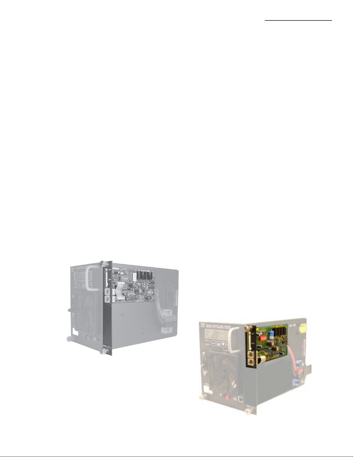
1.2 Identification of USM2.5
Figure 1-2,
New Version of USM2.5
Figure 1-1,
Old Version of USM2.5
704-683-B0-004, Rev. D
7
Page 8
2. Installation
2.1 Inverter Module Removal and Installation
The XM Series 2 Power Supply comes with a field-replaceable Inverter Module, containing
the inverter, battery charger and control logic circuitry. The Inverter Module is designed to
accept USM2.5 plug-in logic upgrades to facilitate remote status monitoring. The Inverter
Module can be removed while the power supply is running on line power. With the Inverter
Module removed, the power supply will continue to operate in a non-standby mode.
Remove the Inverter Module prior to adding the optional USM2.5 circuit board. Follow the
first procedure below precisely.
CAUTION: ALWAYS switch the battery breaker OFF prior to removing the Inverter Module.
XM Series 2 Inverter Module Removal Procedure:
1. Switch OFF the battery breaker. Disconnect the battery input, and the temp
probe cables.
2. Disconnect all remaining cables as needed from the Inverter Module.
3. Loosen the thumbscrews on the Inverter Module.
4. To remove the Inverter Module: grasp ONLY the handle of the Inverter Module,
pull firmly to release the module from the connector. Slide the module
assembly straight out.
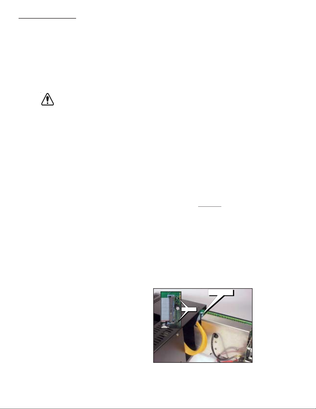
5. Disconnect the Ribbon cable attaching the inverter module to the power
distribution board before sliding the inverter module all of the way out. (Refer
to Figure 2-1.)
XM Series 2 Inverter Module Installation Procedure:
1. Attach the ribbon cable to the inverter module.
2. To reseat the Inverter Module: align the metal shield in the upper and lower
card-guides. Using ONLY the Inverter Module’s handle (
pressure of any kind to the front panel
) firmly drive the module back into the
absolutely apply no
connectors. The connectors are designed to be made with reasonable force.
The thumbscrews are not intended to aid in making these connections, but
to secure the Inverter Module to the chassis.
3. If the Inverter Module is correctly seated the front panel Smart Display will
start-up, and the “Inverter Disconnected Alarm” will NOT be active.
4. Retighten thumbscrews. It is recommended that screws be tightened by
hand ONLY. Avoid using tools to tighten thumbscrews.
5. Reconnect all the cables (TMPR, XPDR, and SYS COM) as needed to the
Communications Module.
6. Verify that the battery breaker is OFF, reconnect the battery input and the
temp probe cables, verify battery polarity, and then finally switch ON the
battery breaker.
Disconnect here
Disconnect here
Unlatch
Figure 2-1, Inverter Module ribbon cable
8
704-683-B0-004, Rev. D
Page 9

2.2 USM2.5 Installation
The optional USM2.5 status monitoring upgrade plugs into the XM Series 2 Inverter Module.
The USM2.5 can be configured for various status monitoring interfaces by setting the DIP
switch. Status monitoring interfaces are listed according to their manufacturer, along with
the associated parts in Section 3.1. The USM2.5 also accommodates a tamper switch
assembly to indicate unauthorized enclosure entries.
CAUTION: The USM2.5 PCB contains static sensitive components that could be easily
damaged if not handled properly.
When installing the USM2.5 use the following procedure:
USM2.5 Installation Procedure:
1. Refer to Section 2.1 for Inverter Module removal.
2. Install the USM2.5 assembly on the Inverter Module:
Tools Required: #2 Phillips head screwdriver.
2. Installation
a) The 2 x 9 pin Strip Connector (Fig. 2-3), must be installed onto the
Inverter Module. A properly installed strip connector will be fully
seated and firmly in place.
b) A new USM2.5 will come with a snap-on support. Position the
USM2.5 over the strip connector and the rear hole for the support
and carefully push into place. Verify the position of the strip connector,
and that the support is fully seated into the Inverter Module mounting
shield.
c) When replacing a USM2.5 the support may already be installed. If
so, align the USM2.5 over the supports and gently rock onto the
strip connector. verify the position of the strip connector, and that
the support is fully seated into the Inverter Module mounting shield.
d) Secure the top of the USM2.5 card to the Inverter Module with the
captive screw fastener. The lower portion is covered by an optional
blanking plate (Fig. 2-2) or an Internal Transponder. Use 2 #6 screws
to secure the blanking plate, or the two captive screw fasteners
with the Internal Transponder.
3. Setup the USM2.5 for proper operation (see Section 3, Configuration):
a) Before reinstalling the Inverter Module, set the DIP switch, SW1 to
the proper configuration settings for the status monitoring interface,
as per Table 3-1 (page 12). Always verify USM2.5 configuration
especially after upgrading or modifying the XM Series 2 Power
Supply.
4. Carefully reinstall the Inverter Module. Refer to section 2.1.
704-683-B0-004, Rev. D
9
Page 10

2. Installation
2.2 USM2.5 Installation
Figure 2-2; Optional Blanking Plate
Part Number 745-419-20
Tamper
Switch
, continued
PEM
Fastener
Figure 2-3; 2X9 Pin Strip Connector
Part Number 540-581-10
External
Transponder
System
Communication
Configuration
Switch SW1
VOUT Scaled DC
Adjust Pot.
Pin 1
Indicator
Figure 2-4; Old Version USM2.5 Front Panel & PCB
Tamper
Switch
External
Transponder
(PEM
Fastener)
Configuration
Switch SW1
VOUT Scaled DC
Adjust Pot.
10
System
Communication
Pin 1
Indicator
Figure 2-5; New Version USM2.5 Front Panel & PCB
704-683-B0-004, Rev. D
Page 11

3. Configuration
3.1 USM2.5 Configuration (V Models)
The following information affects the use of the USM2.5 module on all V5 and VP versions of
the XM2 Power supply. It should be referenced in place of the information contained in the
relevant sections of this manual.
AC Output Current Monitoring On V5 And VP Models
• The AC current from output 1 of the Power supply is present on Pin 13 of
the USM2.5 transponder connector J3.
• The AC current from output 2 of the Power supply is present on Pin 8 of the
USM2.5 transponder connector J3.
This information overrides the following sections of this manual:
• 4.1 USM2.5 Signal Definition – Figure 4-1 USM2.5 Signal Connections (page
16)
• 4.3 USM2.5 Signal Definition – Name: Output Current #1 (page 18)
• 4.3 USM2.5 Signal Definition – Name: Output Current #2 (page 20)
• 5.1 USM2.5 Operations – USM2 Start Up and Test Procedure 3 (page 21)
Note: The output current pins are swapped on the V5 and VP models in relation to the basic
XM2 models. AC Outputs 3 and 4 are not monitored by the USM2.5 module or V5 and
VP Power Supplies.
AC Output Current Scaling on V5 and VP Models
When monitoring the AC Current of Output 1 and Output 2 on the USM2.5 module position 3
of the Function Switch (SW1) should be set to the ON position in order to gain the correct
output current scaling of 0.4VDC/AAC. This is the case for all V5 and VP models independent
of the issue of USM2.5 module used or the rating of the power supply.
This information overrides the following sections of this manual:
• 3.2 USM2.5 Configuration – Table 3-1 USM2.5 DIP Switch Set-up (page 12)
• 3.2 USM2.5 Configuration – SW1 (3): Output Current Scaling (page 13)
704-683-B0-004, Rev. D
11
Page 12

3. Configuration
3.2 USM2.5 Configuration
Refer to the following chart to determine your USM2.5 model
USM2-5 Model: XM2 Model:
USM2.5 XM2-615; XM2-915
USM2.5 22 XM2-1350 @ 60 VAC Output
USM2.5 48 XM2-1350-48
USM2.5 4822 XM2-922
Transpon d er Manuf acturer Alpha Part Number Battery Voltage Output Current
Acterna
Form er l y S EG / Cheetah
AM Communications
Tollgra de
Internal Acterna
Proprietary Transponder
<22A<48US M2-5 (default )
22A<48USM2-5 22
<22A48USM2-5 48
22A48USM2- 5 48 22
<22AN/AUSM2-5 TG
22AN/AUSM2-5 TG22
<22A<48USM2-5 INT-ACTP
22A<48USM2-5 INT-ACTP22
<22A48USM2-5 INT-ACTP48
22A48USM2-5 INT-ACTP4822
Table 3-1; USM2.5 DIP Switch Setup
NOTE: Switch 1-3 should always be ON for units equipped with the ONU option.
Transpon d er Manuf acturer Alpha Part Number Battery Voltage Output Current
Acterna
Form er l y S EG / Cheetah
AM Communications
Tollgra de
Internal Acterna
Proprietary Transponder
<22A<48US M2-5 (default )
22A<48USM2-5 22
<22A48USM2-5 48
22A48USM2- 5 48 22
<22A<48USM2-5 AM
22A<48USM2-5 AM22
<22A48USM2-5 AM48
22A48USM2- 5 AM4822
<22AN/AUSM2-5 TG
22AN/AUSM2-5 TG22
<22A<48USM2-5 INT-ACTP
22A<48USM2-5 INT-ACTP22
<22A48USM2-5 INT-ACTP48
22A48USM2-5 INT-ACTP4822
1 2 3 4 5 6 7 8
ON ON
ON ON ON
OFF OFF OFF OFF OFF
ON ON
ON ON ON
OFF
ON
OFF
ON ON
OFF OFF OFF OFF
OFF OFF
ON ON
ON ON ON
OFF OFF OFF
OFF
OFF OFF
Batt
Scale
volts/volt
.5VDC
.1VDC
.5VDC
.3 VDC
.1VDC
.5VDC
.1VDC
Voltage
(+)5VDC
(+)15VDC
(+)5VDC
(+)24VDC
Switch SW1
OFF OFF OFF
OFF OFF
OFF OFF
ON ON
ON
OFF OFF OFF
OFF OFF
OFF OFF OFF
OFF OFF
ON
OFF
ON
OFF
ON ON
Xpndr
ON
OFF
ON
OFF
ON ON
OFF
ON
Out V
Scale
volts/volt
.5VAC
.15VDC
.5VAC
ON
ON
ON
ON
ON
ON
ON
ON
OFF
OFF
ON
ON
ON
Tamper
Non inverting
Inverting
Non inverting
OFF OFF
OFF OFF
OFF OFF
OFF
OFF
OFF
OFF
OFF
ON
ON
OFF OFF
OFF OFF
OFF OFF
OFF OFF
OFFOFF OFF
ON<22A<48USM2-5 AM
ON22A<48USM2-5 AM22
ON<22A48USM2-5 AM48
ON22A48USM2- 5 AM4822
OFF
OFF
Out I
Scale
volts/amp
.4VDC
12
Table 3-2; USM2.5 Transponder Output Voltages
704-683-B0-004, Rev. D
Page 13

3. Configuration
3.2 USM2.5 Configuration,
Figure 3-1; USM2.5 Switch Location
(Old Version )
continued
Figure 3-2; USM2.5 Switch Location
(New Version )
Always verify USM2.5 configuration especially after upgrading or modifying the XM Series 2
Power Supply.
Function Switch SW1 Reference
The following information describes each switch position (1–8) for the DIP switch SW1. SW1
is an eight switch component used primarily to select analog scaling and digital signal
polarity for the USM2.5 card.
SW1 (1 and 2): Inverter Battery Voltage Scaling Select
SW1, positions 1 and 2 are used together to select the appropriate scaling for the XM
Series 2 battery voltage measurement, measured at J4 pin 5.
SW1 (1)SW1 (2)Battery Scaling
OFF OFF 0.1VDC/VDC
OFF ON 0.3VDC/VDC
ON OFF 0.3VDC/VDC Same as previous setting.
ON ON 0.5VDC/VDC
SW1 (3): Output Current Scaling
SW1, position 3 is used to select the appropriate scaling for the XM Series 2 AC OUTPUT
CURRENT#1, measured at J4 pin 8 and AC OUTPUT CURRENT #2 pin 13.
SW1 (3)Output Current #1, #2
OFF 0.4VDC/AAC for Power Supply Output Current rating less than 20A.
ON 0.4VDC/AAC for Power Supply Output Current rating equal to or greater than 20A.
NOTE: Switch 1-3 should always be ON for units equipped with the ONU option.
704-683-B0-004, Rev. D
13
Page 14

3. Configuration
3.2 USM2.5 Configuration,
SW1 (4) and (8): Auxiliary DC Voltage Select
SW1, position 4 and 8 are used to select the voltage of the AUX DC delivered to the
transponder, measured at J4 pin 2.
SW1 (4) SW1 (8) Aux DC Voltage
OFF OFF + 5 VDC
ON OFF + 24 VDC
OFF ON + 15 VDC
ON ON N/A Incorrect Switch Setting
SW1 (5) and (6): Output Voltage AC or DC Scaling Select
SW1, position 5 and 6 is used to select the AC or DC representation of the XM
Series 2 AC OUTPUT VOLTAGE measurement, measured at J4 pin 4.
SW1 (5) SW1 (6) Output Volts (DC)
OFF OFF N/A No output at J4 pin 4
OFF ON 0.5 VAC Per Volt AC Output
ON OFF 0.15 VDC Per Volt AC Output
ON ON N/A Incorrect Switch Setting
NOTE: DC setting accuracy can be calibrated by adjusting the front panel potentiometer
(see Fig 2-4).
continued
SW1 (7): Tamper Status Polarity Select
SW1, position 7 is used to select between inverted or non-inverted signal polarity
for the system’s transponder measured at J4 pin 7.
SW1 (7) Tamper Status
OFF Not inverted (switch opens; Tamper Status goes HIGH)
ON Inverted (switch opens; Tamper Status goes LOW)
14
704-683-B0-004, Rev. D
Page 15

4. Signal Definitions
4.1 USM2.5 Signal Definition
IMPORTANT NOTE: For the USM2.5 to function correctly, OUTPUT (N) must be grounded to
the chassis of the XM Series 2. In a typical installation, this is automatically done
through the SPI, but during bench testing this connection will have to be manually made
by placing a jumper between the power supply Output Neutral and chassis ground.
HIGH is typically defined as AUX DC Voltage ± 10% (+5VDC, +15VDC, or +24VDC as set by
configuration). Voltage exceeding AUX DC is abnormal, but will not likely damage the
USM2.
(90%AUX DC < HIGH < AUX DC)
LOW is typically defined as 0VDC, however any nonnegative voltage between 0VDC and +1VDC
will be accepted by the USM2.5 as LOW.
(0VDC < LOW < 1VDC)
Sample 1 XMS 2
USM2.5
External
Acterna
USM2.5
AM
USM2.5
TG
Au xiliar y D C Out N/A +5VDC +15VDC +5V DC
AC Output Voltage 63VAC 31.5VAC 31.5VAC 9.45V D C
Bat ter y V ol tage
(36 VDC Nominal)
41.4VDC 20 .7V D C 20.7VDC 4.14VDC
Output Current 7A 2.8VD C 2.8VDC 2.8VDC
AC In p u t V oltage 240VA C N/A N/A N/A
Sample 2 XMS 2
USM2.5
External
Acterna
USM2.5
External
AM
USM2.5
External
TG
Au xiliar y D C Out N/A +5VDC +15VDC +5V DC
AC Output Voltage 87VAC 43.5VAC 43.5VAC 13.05VDC
Bat ter y V ol tage
(36 VDC Nominal)
39.6VDC 19 .8V D C 19.8VDC 3.96VDC
Output Current 14A 5.6VDC 5.6VDC 5.6VDC
AC In p u t V oltage 120VA C N/A N/A N/A
* Input voltages will me as ure approximately 2.7 VAC for 240 VAC input and 2.5 VA C for 120 VAC input.
USM2.5
Internal
Acterna
+24VDC
31.5VAC
20.7VDC
2.8VDC
Approx.
2.7VAC*
USM2.5
Internal
Acterna
+24VDC
43.5VAC
20.7VDC
2.8VDC
Approx.
2.5VAC*
704-683-B0-004, Rev. D
Table 4-1; USM2.5 Output Scaling Samples
15
Page 16

4. Signal Definitions
4.1 USM2.5 Signal Definition,
This Section provides specific details of all signals (input and output) provided on the XPDR
and TMPR Connectors when set up as a USM2.5 (default setting).
Tamper swi t ch return (GND)
Tamper switch sensor
Output current 1
for ONU equipped units
Output current 2
for ONU equipped units
Output current 2 13
Ground 12
Test / Reset 11
Output fail 10
AC input voltage 9
Output current 1 8
Tamper status
Equipment Fail
Battery voltage
AC output voltage
Standby / Line fail
Aux DC output
Ground
continued
2
1
7
6
5
4
3
2
1
J5
Tamper Switch Input
J4
Transponder I/O
DC Scaling Adjust
Pin 1
Figure 4-1; USM2.5 Signal Connections
Name: Common
Pin: J4-1
Signal Type: Ground reference / return
Referenced to: N/A
Description: Ground / return reference for ALL signals (analog, input & output) on
the USM2.5. Same as pins J4-12 and J5-2.
Name: Auxiliary DC Out
Pin: J4-2
Signal Type: Power
Referenced to: Common (J4-1, J4-12)
Description: This pin provides power for transponder pull up resistors as needed.
Auxiliary DC Out is not intended to provide complete logic &
transceiver power to the transponder, except in the case of internal
transponders
Parameters: Current drawn from this pin should NOT exceed 100mA under any
circumstance. Auxiliary DC Out is overcurrent protected by the
foldback of the switching power supply
How to test: Verify voltage on pin #2 is +5VDC, +15VDC, or +24VDC; (all within
10% tolerance) as set by configuration.
Name: Standby / Line Fail
Pin: J4-3
Signal Type: USM2.5 Discrete output
Referenced to: Common (J4-1, J4-12)
Description: This USM2.5 output indicates the state of the XM2 inverter.
Active Means: The XM2’s inverter is ON, and/or the AC line input has failed.
Active State: LOW
Inactive Means: The XM2’s inverter is NOT ON.
Inactive State: HIGH
How to test: With the XM2’s inverter ON, verify LOW on J4-3.
16
704-683-B0-004, Rev. D
Page 17

4. Signal Definitions
4.1 USM2.5 Signal Definition,
Name: AC Output Voltage
Pin: J4-4
Signal Type: USM2.5 Analog Output
Referenced to: Common (J4-1, J4-12)
Description: This pin provides a scaled, analog representation of the XM2’s
output voltage.
Parameters: This analog output should be 0.5VAC or 0.15VDC per VAC of the
XM2’s output. The calculated voltage should be within 5% of the
measured output voltage.
How to test: Verify voltage on pin #4 is 0.5VAC, or 0.15VDC per VAC of the
XM2’s output, as set by configuration. Front panel potentiometer
can be used to adjust the DC scaled voltage.
Name: Battery Voltage
Pin: J4-5
Signal Type: USM2.5 Analog Output
Referenced to: Common (J4-1, J4-12)
Description: This pin provides a scaled, analog representation of the XM2’s
battery string voltage.
Parameters: This analog output should read 0.1VDC, 0.3VDC, or 0.5VDC per
VDC of the XM2’s battery voltage, as set by configuration
SW1(pins 1 and 2).
How to test: Verify voltage on J3-5 is 0.1 VDC, 0.3VDC, or 0.5VDC per VDC of
the XM2’s battery voltage, as set by configuration.
continued
Name: Equipment Fail Alarm
Pin: J4-6
Signal Type: USM2.5 Discrete Output
Referenced to: Common (J4-1, J4-12, J5-2)
Description: This USM2.5 output indicates the general health of the XM2.
Active Means: An active Equipment Fail Alarm pin indicates a ‘latched’ failure of
an automated, local or remote inverter test or some other major
alarm within the XM2. No matter the cause, an Equipment Fail
Alarm indicates the XM2 will NOT perform as required and
should be serviced. Once this condition has been detected by
the USM2.5, the Equipment Fail Alarm will stay active until reset
by the successful completion of a Self Test (either locally or
remotely).
Active State: LOW
Inactive Means: Utility AC line input is present and no inverter failures have been
detected.
Inactive State: HIGH
How to Test: Verify that Equipment Fail Alarm is not currently latched HIGH.
With utility AC line and batteries present, initiate a remote
inverter test (see description of Pin 11 Test/Reset). Next,
simulate a battery failure by Switching XM2’s battery circuit
breaker OFF, the Equipment Fail Alarm should go LOW. Close
the battery circuit breaker; the Equipment Fail Alarm will stay
LOW. To clear the Equipment Fail Alarm, initiate an inverter test,
wait one minute, stop the inverter test.
704-683-B0-004, Rev. D
17
Page 18

4. Signal Definitions
4.1 USM2.5 Signal Definition,
Name: Tamper Switch Status
Pin: J4-7
Signal Type: USM2.5 Discrete Output
Referenced to: Common (J4-1, J4-12)
Description: USM2.5 output indicates the current state of the XM2’s enclosure
tamper switch. This is a non-latching type alarm.
Active Means: The enclosure door is opened or the tamper switch is
disconnected.
Active State: HIGH
Inactive Means: The enclosure tamper switch is properly connected and the door
is closed.
Inactive State: LOW
How to Test: Disconnect any tamper switch from the USM2.5 TMPR
connector. Short USM2.5 TMPR connector; the USM2.5 tamper
status (pin #7) should go LOW. Remove the short on USM2.5
TMPR connector (open circuit) and the Tamper Status output
should go HIGH.
NOTE: The tamper output polarity can be switched using SW1-7
continued
Name: Output Current #1
Pin: J4-8 (J4-13 for ONU equipped units)
Signal Type: USM2.5 Analog Output #1
Referenced to: Common (J4-1, J4-12)
Description: This USM2.5 analog output is a DC approximation of the total
XM2 AC output #1 current.
Parameters: 0.4VDC per AC ampere XM2 output.
How to Test: Verify voltage on J4-8 is 0.4VDC per AC ampere XM2 output #1.
(± 5% tolerance)
NOTE: The output current scale is dependant upon SW1-3
Name: AC Input Voltage (formerly not used on USM2 cards)
Pin: J4-9
Signal Type: USM2.5 Analog Input
Referenced to: Common (J4-1, J4-12)
Parameters: This analog output should be 0.0211 VRMS per VAC output for
120 VAC systems or 0.0113 VRMS per VAC output for 240 VAC
systems. (Approx. 2.5 VAC.)
How to Test: Verify that the voltage on J4 pin 9 is .0211 VRMS or .0113 VRMS per VAC
of the XM2’s input voltage (true RMS voltmeter must be used to read this
signal). (Approx. 2.7 VAC.)
18
704-683-B0-004, Rev. D
Page 19

4. Signal Definitions
4.1 USM2.5 Signal Definition,
Name: Output Fail Alarm
Pin: J4-10
Signal Type: USM2.5 Discrete Output
Referenced to: Common (J4-1, J4-12)
Description: This USM2.5 signal indicates the state of the AC output. A non-
latching signal, the Output Alarm will match the state of the
power supply output in real-time.
Active Means: The XM2’s AC output has failed.
Active State: LOW
Inactive Means: The XM2’s AC output is OK.
Inactive State: HIGH
NOTE: Removing the output fuse will result in a loss of power to the cable system (load).
Do not attempt this test without first transferring the load to a Service Power Supply
How to Test: Remove the XM2’s AC output fuse; verify J4-10 is LOW. Return
the XM2’s fuse; verify J4-10 is HIGH.
Name: Test/Reset
Pin: J4-11
Signal Type: USM2.5 Discrete Input
Referenced to: Common (J4-1, J4-12)
Description: This USM2.5 input controls remote test of the XM2’s inverter and
allows reset of a latched USM2.5 Equipment Fail Alarm. This
control signal originates from the transponder.
Active Means: An active Test / Reset pin indicates that the XM2 has been
commanded to initiate and hold a remote inverter test.
Active State: LOW, a transition from HIGH to LOW will indicate to the USM2.5
that the Test/Reset pin has been activated. The pin will be
considered active by the USM2.5 for the duration that the pin is
held LOW.
Inactive Means: The XM2 is not commanded to perform or hold a remote inverter
test. Any previously held test will be ended when the input is
transitioned from active to inactive.
Inactive State: HIGH
How to test: To perform a test at the XM2, disconnect the transponder from
the USM2.5. With line and battery applied to the XM2, carefully
short and hold the Test/Reset J4-11 to ground (J4-1), the XM2 will
immediately start inverter test mode. Wait at least 1 minute then
release J4-11 from ground and the inverter test mode will end,
and any latched Equipment Fail Alarm should clear.
continued
Resetting a latched Equipment Fail Alarm:
704-683-B0-004, Rev. D
If a USM2.5 Equipment Fail Alarm is latched when the Test/
Reset pin is made active and a successful inverter test is
completed, the Equipment Fail Alarm will be cleared (i.e. J4-6
change to inactive).
19
Page 20

4. Signal Definitions
4.1 USM2.5 Signal Definition,
Name: Common
Pin: J4-12
Signal Type: Ground reference / return
Referenced to: N/A
Description: Ground / return reference for ALL signals (analog, input & output)
on the USM2.5. Same as J4 pin 1 and J5 pin 2.
Name: Output Current #2
Pin: J4-13 (J4-8 for ONU equipped units)
Signal Type: USM2.5 Analog Output #2
Referenced to: Common (J4-1, J4-12)
Description: This USM2.5 analog output is a DC approximation of the total
XM2 AC output #2 current.
Parameters: 0.4VDC per AC ampere XM2 output.
How to Test: Verify voltage on J4-13 is 0.4VDC per AC ampere XM2 output #2
(±5% tolerance).
NOTE: The output current scale is dependant upon SW1-3
Name: Tamper Switch In
Pin: J5-1
Signal Type: USM2.5 Discrete Input (dry contact switch)
Referenced to: J5-2
Description: Dry contact tamper switch input. Left open circuit, this USM2.5
input will be pulled up to +5VDC.
Active Means: The enclosure’s door is open or the tamper switch is not
connected.
Active State: OPEN
Inactive Means: The enclosure’s door is closed.
Inactive State: SHORT
How to test: See ‘How to Test’ for J4-7 (page 17).
continued
20
Name: Tamper Switch Return
Pin:J5-2
Signal Type: Ground Reference/return
Referenced to: N/A
Description: Return / ground for Tamper switch.
NOTE: ALL values are provided for troubleshooting and reference purposes ONLY.
704-683-B0-004, Rev. D
Page 21

5.1 USM2.5 Operations
USM2.5 Start up and Test Procedure
The XM Series 2 power supply should be fully tested before attempting any USM2.5 operations.
Refer to the XM Series 2 technical manual for details. Once the power supply has been
verified as “GOOD” the USM2.5 can then be tested as follows:
1. Verify the USM2.5 installation by checking:
• Configuration settings of switch SW1.
• USM2.5 is properly installed onto Communication Module, and that the
Communication Module is correctly installed into the XM Series 2 power supply.
• Tamper switch is properly installed and connected.
• Data cable from the USM2.5 to the transponder is correctly installed.
2. Unplug transponder’s data cable from the USM2.5.
3. Using a true RMS multimeter, verify the USM2.5’s analog data (set by configuration) on
the J4 connector by checking (ground on J4-1):
• Auxiliary DC output on J4-2
• AC Output Voltage Level on J4-4
• Battery Level output on J4-5
• Output Current#1 level on J4-8 (J4-13 for ONU equipped units)
• Output Current#2 level on J4-13 (J4-8 for ONU equipped units)
• AC input voltage level on J4 pin 9
5. Operation
4. Using a true RMS multimeter, verify the USM2.5’s Digital data (set by configuration) on
the J3 connector by checking (ground on J4-1):
• Standby Status Alarm J4-3, active any time inverter in ON.
• Equipment Fail Alarm J4-6, active if test failure or low battery condition.
• Tamper Alarm J4-7, active when the enclosure’s door is open.
NOTE: Removing the output fuse will result will result in a loss of power to the
cable system (load).
load to a Service Power Supply.
• Output Alarm J4-10, active when the XM Series 2’s AC output has failed.
5. Verify remote USM2.5 control on the J2 connector by shorting Pin11 to ground (J4-1):
• Test/Reset J4-11, shorted XM Series 2 inverter Test ON, open inverter Test OFF.
NOTE: Successful completion of test steps 1-5 above is a very good indication that the
USM2.5 is operating correctly, if the unit fails any of the tests, repeat the test to verify
failure, and replace USM2.5 as needed.
6. Plug transponder’s data cable back into the USM2.5. Repeat test steps 3-5; local results
should remain the same. If results do NOT remain the same, this is an indication of a
possible transponder failure.
7. Review analog data at status monitoring center. The reported data should be similar to
values seen at the power supply.
8. Initiate an inverter test command from the status monitoring center. The power supply
should go into test as commanded. Monitor command signals from the transponder on
the USM2.5 connector J2 using a multimeter by checking:
• Test/Reset J4-11, active XM Series 2 inverter ON, inactive inverter OFF.
Do not attempt this test without first transferring the
NOTE: Test steps 6-8 are used to verify the transponder and the status monitoring
704-683-B0-004, Rev. D
system, if any of the tests fail; retest, verify failure, troubleshoot status monitoring
system (less USM2.5) as needed.
21
Page 22

6. Troubleshooting
6.1 Troubleshooting the Communications Link
Occasionally the communications link between the XM Series 2 power supply and the headend
site may appear to break down. Updates to and from the power supply may not take place,
or data received may be faulty. When this happens, isolate and correct the failed elements in
a precise fashion to avoid extended troubleshooting times or the possibility spreading a
potential failure from site to site.
Symptom: No Remote Control (Inverter Test)
Diagnosis: To start, verify that USM2.5 J4-11 (Test/Reset) are HIGH; change
Repair Solution: If the remote commands are present, goes from HIGH to LOW,
Symptom: Incorrect Scaling voltage reported.
Diagnosis: Verify that the USM2.5 is configured correctly; then verify the
Repair Solution: If the scaling voltage reported is NOT correct, replace the
state via remote command pins should go LOW.
replace the USM2.5; if not, troubleshoot the transponder and RF
section.
XM2 Output in question; verify USM2.5 scaling.
USM2.5. If scaling voltages are correct, troubleshoot the
transponder and RF section.
Symptom: Status monitoring reports “Comm Error”.
Diagnosis: Verify that the USM2.5 is correctly connected to the transponder,
and that the transponder is correctly powered (per transponder
documentation).
Repair Solution: Correct connections as needed.
Symptom: No Auxiliary DC output
Diagnosis: Verify Auxiliary DC output by checking voltage on J4-2 with the
USM2.5 disconnected from the status monitor; if voltage is
correct, reconnect status monitor and check again.
Repair Solution: With the USM2.5 disconnected from the transponder the
Auxiliary DC voltage is NOT correct, replace the USM2.5. If AUX
DC voltages is correct with transponder, troubleshoot the
transponder and RF section.
22 704-683-B0-004, Rev. D
Page 23

7.1 Parts
The following parts can be purchased by calling your local Alpha representative:
7. Parts
Part Name:
Ribbon Cable
2 x 9 Header
Hardware Kit
Includes:
2 x 9 Header
Plastic Standoffs
Screws
Sheet Metal Kit
Includes:
Faceplate with silkscreen
Mounting Hardware
Alpha Part Number:
874-992-20
540-581-10
745-153-22
745-153-21
704-683-B0-004, Rev. D
23
Page 24

8. Reference
8.1 USM2.5 Signals, Quick Reference
PIN
2
1
13
12 Ground
11
10
9
8 Analog Scaled analog representation of UPS output current #1. Scaling: 0.4 VDC per AMP output
7 Tamper Status
Signal
Name
Tamper Switch
Return
Tamper Switch
Output Current 2
(Output Current
1 for ONU
equipped units)
Test / Reset
Output Fail
Alarm
AC Input
Voltage
Output Current 1
(Output Current
2 for ONU
equipped units
Type
(Ground)
Discrete
(In)
Analog
Ground
Discrete
(in)
Discrete
(Out)
Analog
Discrete
(Out)
Signal Description
Return for Tamper Switch input to USM2-5 (same as J4 pins 1 and 12)
Tamper Switch input to USM
Scaled analog representation of UPS output current #2. Scaling: 0.4 VDC per Amp output
Ground reference for all signal and power (same as J5 pin 2 and J4 pin 1).
Command to UPS to initiate and hold a UPS battery and inverter test. Pulling the signal to ground for >
100ms will initiate the inverter test. Releasing the signal will allow the test to end. If the UPS has a
latched alarm, successful completion of the test will clear the alarm.
Indicates the state of the UPS output. Signal pulled up to AUX DC.
Scaled representation of the UPS input voltage. Scaling se t by UPS, input voltage can be
.0211 (120 in) or .0113 (240 in) Volts per input volt.
Indicates state of the enclosure tamper switch. Signal pulled up to AUX DC. Polarity of signal
determined by configuration.
Equipment Fail
6
5 Battery Voltage Analog
4
3
2
1 G round Ground Ground reference for all signal and power (same as J5 pin 2 and J4 pin 12).
Alarm
AC Output
Voltage
Standby / Line
Fail Alarm
Auxiliary DC
Out
Discrete
(Out)
Analog
Discrete
(Out)
Power Auxiliary output power for transponder. Voltage set by configuration; +5, +15, or +24 VDC
Indicates power supply equipment failure. Signal pulled up to AUX DC.
Scaled analog representation of UPS battery pack voltage. Scaling set by configuration. Can be
.5 VDC or .15 VDC per battery volt.
Scaled representation of the UPS output voltage. Scaling set by configuration. Can be .5 VDC or
.15 VDC per output volt.
Indicates the state of the UPS inverter. Signal pulled up to AUX DC.
IMPORTANT NOTE: In order for the USM2.5 to function correctly, OUTPUT (N) must be grounded to
the XM Series 2’s chassis! During normal operation this is automatically done though the SPI, but
during bench testing this ground will have to be manually maintained, by placing a jumper between
the Output Neutral and chassis ground.
24
704-683-B0-004, Rev. D
Page 25

8. Reference
8.2 Testing and Troubleshooting, Quick Reference
USM2.5 Start up and Test Procedure
The XM Series 2 power supply should be fully tested before attempting any USM2.5 operations.
Refer to the XM Series 2 technical manual for details. Once the power supply has been verified as
“GOOD” the USM2.5 can then be tested as follows:
1. Verify the USM2.5 installation by checking:
• Configuration settings of switch SW1.
• USM2.5 is properly installed onto Communication Module, and that the
Communication Module is correctly installed into the XM Series 2 power supply.
• Tamper switch is properly installed and connected.
• Data cable from the USM2.5 to the transponder is correctly installed.
2. Unplug transponder’s data cable from the USM2.5.
3. Using a true RMS multimeter, verify the USM2.5’s analog data (set by configuration) on
the J4 connector by checking (ground on J4-1):
• Auxiliary DC output on J4-2
• AC Output Voltage Level on J4-4
• Battery Level output on J4-5
• Output Current#1 level on J4-8
• Output Current#2 level on J4-13
• AC input voltage level on J4 pin 9
4. Using a true RMS multimeter, verify the USM2.5’s Digital data (set by configuration) on
the J3 connector by checking (ground on J4-1):
• Standby Status Alarm J4-3, active any time inverter in ON.
• Equipment Fail Alarm J4-6, active if test failure or low battery condition.
• Tamper Alarm J4-7, active when the enclosure’s door is open.
NOTE: Removing the output fuse will result will result in a loss of power to the
cable system (load).
load to a Service Power Supply.
• Output Alarm J4-10, active when the XM Series 2’s AC output has failed.
5. Verify remote USM2.5 control on the J2 connector by shorting Pin11 to ground (J4-1):
• Test/Reset J4-11, shorted XM Series 2 inverter Test ON, open inverter Test OFF.
NOTE: Successful completion of test steps 1-5 above is a very good indication that the
USM2.5 is operating correctly, if the unit fails any of the tests, repeat the test
to verify failure, and replace USM2.5 as needed.
6. Plug transponder’s data cable back into the USM2.5. Repeat test steps 3-5; local results
should remain the same. If results do NOT remain the same, this is an indication of a
possible transponder failure.
7. Review analog data at status monitoring center. The reported data should be similar to
values seen at the power supply.
8. Initiate an inverter test command from the status monitoring center. The power supply
should go into test as commanded. Monitor command signals from the transponder on
the USM2.5 connector J2 using a multimeter by checking:
• Test/Reset J4-11, active XM Series 2 inverter ON, inactive inverter OFF.
Do not attempt this test without first transferring the
NOTE: Test steps 6-8 are used to verify the transponder and the status monitoring
system, if any of the tests fail; retest, verify failure, troubleshoot status monitoring
system (less USM2.5) as needed.
704-683-B0-004, Rev. D
25
Page 26

Page 27

Page 28

Alpha Technologies
Power
Alpha T echnologies
3767 Alpha Way
Bellingham, WA 98226
USA
Tel: +1 360 647 2360
Fax: +1 360 671 4936
Web: www.alpha.com
Alpha T echnologies Ltd.
4084 McConnell Court
Burnaby, BC, V5A 3N7
CANADA
Tel: +1 604 430 1476
Fax: +1 604 430 8908
Alpha T echnologies
Europe Ltd.
Twyford House
Thorley
Bishop’s Stortford
Hertfordshire
CM22 7PA
UNITED KINGDOM
T el: +44 0 1279 501 1 10
Fax: +44 0 1279 659870
Alpha T echnologies GmbH
Hansastrasse 8
D-91126 Schwabach
GERMANY
T el: +49 9122 79889 0
Fax: +49 9122 79889 21
Alphatec, Ltd
P .O. Box 56468
Limassol, Cyprus
CYPRUS
T el: +357-25-375675
Fax: +357-25-359595
AlphaTek, ooo
Khokhlovskiy Pereulok 16
Stroenie 1
109028 Moscow
RUSSIA
Tel: +7 095 916 1854
Fax: +7 095 916 1349
Alphatec Baltics
S. Konarskio G . 49
Vilnius 2009
LITHUANIA
Tel: +350 5 210 5291
Fax: +350 5 210 5292
Alpha T echnologies
5 Avenue Victor Hugo
F-92140 Calmart France
FRANCE
Tel: +33 3 41 90 07 07
Fax: +33 1 41 90 93 12
Copyright © 2006 Alpha Technologies, Inc. All rights reserved. Alpha is a registered trademark of Alpha Technologies. 704-683-B0-004, Rev. D.
Due to continuing product improvements, Alpha reserves the right to change specifications without notice.
®
 Loading...