

Page 1
UPE-M Series
Metered Ground Mount Enclosures
Installation and Operation Manual
UPE-M3, UPE-M6, UPE-M8, 10KAIR and 65KAIR
Effective: November, 2004
Alpha T echnologies
Page 2

Alpha T echnologies
Power
®
Page 3

UPE-M Installation
031-145-C0-002, Rev . B
Effective Date: November, 2004
Copyright© 2004
Alpha Technologies, Inc.
A Member of the Alpha Group
Photographs contained in this manual are for illustrative purposes only . These photographs may not match your
installation.
Operator is cautioned to review the drawings and illustrations contained in this manual before proceeding. If there
are questions regarding the safe operation of this powering system, please contact Alpha Technologies or your
nearest Alpha representative.
Alpha shall not be held liable for any damage or injury involving its enclosures, power supplies, generators,
batteries, or other hardware if used or operated in any manner or subject to any condition not consistent with its
intended purpose, or is installed or operated in an unapproved manner , or improperly maintained.
Contacting Alpha Technologies: www.alpha.com
OR
For general product information and customer service (7 AM to 5 PM, Pacific Time), call
1-800-863-3930
For complete technical support, call
1-800-863-3364
7 AM to 5 PM, Pacific Time or 24/7 emergency support
3031-145-C0-002 Rev . B
Page 4

T able of Contents
Safety Notes ......................................................................................................................... 6
1.0 Pre-Installation............................................................................................................ 7
1.1 Introduction ...................................................................................................... 7
1.2 Inner Tray Layout............................................................................................ 11
2.0 Site Preparation ....................................................................................................... 12
2.1 Site Considerations....................................................................................... 12
2.2 Enclosure Pedestal Support .......................................................................... 13
2.3 Pad Fabrication............................................................................................. 14
2.4 Enc losure Groun ding ..................................................................................... 15
3.0 Installation ................................................................................................................ 16
3.1 Enclosure Installation ..................................................................................... 16
3.2 Utility Powering.............................................................................................. 17
3.3 Service Power Inserter................................................................................... 23
3.4 Battery Installation .......................................................................................... 24
3.5 Power Supply Installation ............................................................................... 27
3.6 Power Supply Connections............................................................................ 28
3.7 Lightning Arrester (LA-P+) Option .................................................................. 29
3.8 LRI Option ..................................................................................................... 29
3.9 Enclosure Cooling Fan (optional)................................................................... 30
4 031-145-C0-002 Rev. B
Page 5

List of Figures
Fig. 1-1, UPE-M3 and UPE-M6 Meter Compartment ......................................................... 7
Fig. 1-2, UPE-M8 Meter Compartment .............................................................................. 7
Fig. 1-3, UPE-M8 Dimensions........................................................................................... 8
Fig. 1-4, UPE-M6 Dimensions........................................................................................... 9
Fig. 1-5, UPE-M3 Dimensions......................................................................................... 10
Fig. 1-6, Inner T rays ......................................................................................................... 11
Fig. 2-1, Pedestal Support (PS-1) Dimensions................................................................ 13
Fig. 2-2, Concrete Pad Dimensions................................................................................. 14
Fig. 2-3, En clo sur e Grounding ......................................................................................... 15
Fig. 3-1, Enclosure Mounting Holes ................................................................................. 16
Fig. 3-2, 65K-AIR Enclosure (Rear View)......................................................................... 1 8
Fig. 3-3, 10K-AIR Enclosure (Rear View)......................................................................... 1 8
Fig. 3-4, Meter Base Configurations ................................................................................ 19
Fig. 3-5, Meter Base Configurations ................................................................................ 20
Fig. 3-6, Fuse/Receptacle Configurations for 65K-AIR Enclosures................................... 21
Fig. 3-7, Fuse/Receptacle Configurations for S tandard Enclosures.................................. 22
Fig. 3-8, Removing SPI Cover ......................................................................................... 23
Fig. 3-9, Connecting Coax to SPI Output Port .................................................................. 23
Fig. 3-10, Battery T erminal Assembly ................................................................................. 24
Fig. 3-11, Battery Pack...................................................................................................... 26
Fig. 3-12, Battery and Output Power Connections.............................................................. 28
5031-145-C0-002 Rev . B
Page 6
Safety Notes
Review the drawings and illustrations contained in this manual before proceeding. If there are any questions
regarding the safe installation or operation of the system, contact Alpha Technologies or the nearest Alpha
representative. Save this document for future reference.
T o reduce the risk of injury or death, and to ensure the continued safe operation of this product, the following
symbols have been placed throughout this manual. Where these symbols appear, use extra care and attention.
HAZARDOUS CONDITION
The use of A TTENTION is for specific regulatory/code requirements that may af fect the placement of equipment
and installation procedures.
A NOTE provides additional information to help complete a specific task or procedure.
A CAUTION presents safety information to prevent damage to equipment.
A W ARNING presents safety information to PREVENT INJUR Y OR DEA TH to the technician/
user.
6 031-145-C0-002 Rev. B
Page 7
1.0 Pre-Installation
1.1 Introduction
The Alpha UPE-M series of metered CA TV power supply enclosures are a secure, ruggedly designed,
water-resistant enclosure with separate raceways for utility power and CA TV wiring. The enclosure
is designed to meet code and safety standards specified by EUSERC and the NEC.
The utility meter compartment is isolated from the CA TV compartment. Utility access doors contain
padlock hasps with separate sealing screws. A small hole is provided in each screw and hasp to
accommodate a lead wire seal. The CA TV doors have flush-mounted key locks installed.
The utility meter compartment contains a hinged, lockable, Lexan window for meter reading. The
utility meter can be accessed by lifting the hinged door .
The standard UPE-M enclosure has a fault current interrupt rating of 10,000A. A 65,000A version is
also available.
There are three basic models in the UPE-M series, available in both 10KAIR and 65KAIR
configurations. The UPE-M3 and UPE-M6 models are designed for the XM2-615, XM2-915, and
XM2-1350 power supplies with 36V inverters. The UPE-M8 model is designed for the XM2-1350,
XM2-615, and XM2-922 power supplies with 48V inverters.
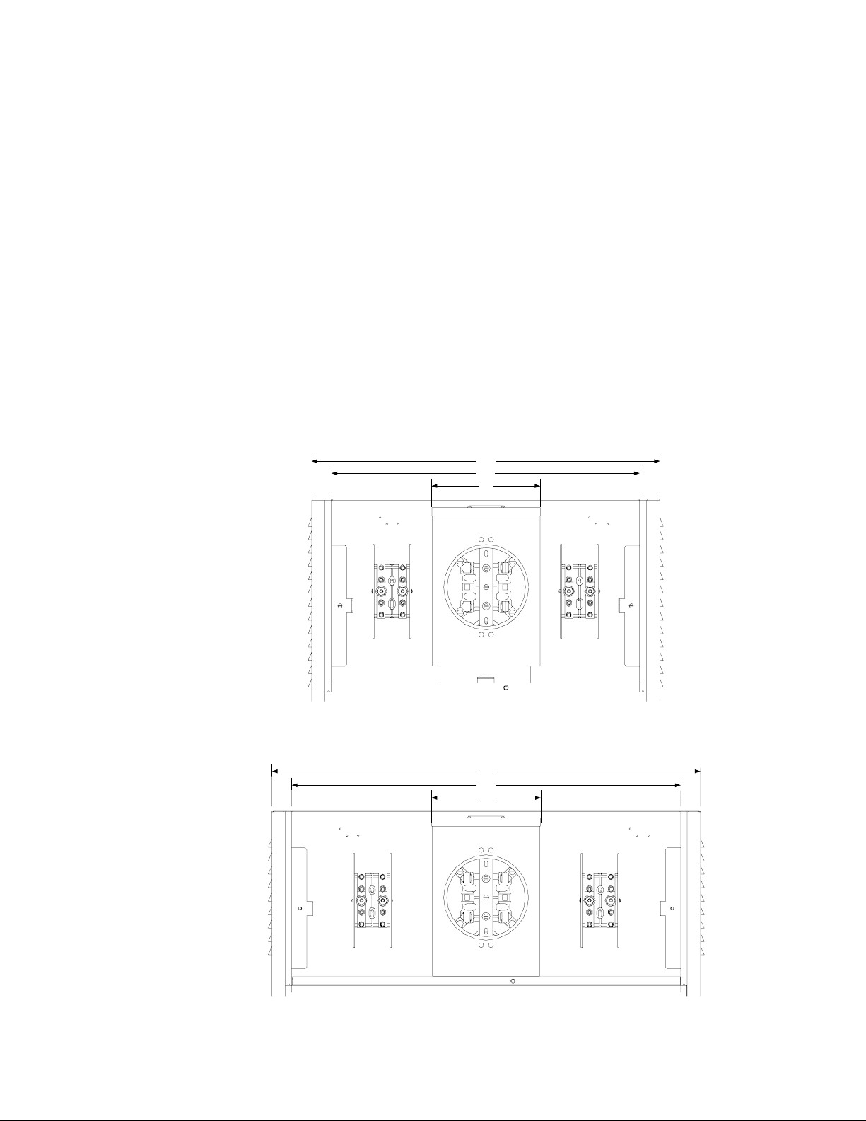
26.0"
23.0"
8.1"
Fig. 1-1, UPE-M3 and UPE-M6 Meter Compartment,
with Test Bypass Blocks
32.0"
29.0"
8.1"
Fig. 1-2, UPE-M8 Meter Compartment,
with Test Bypass Blocks
7031-145-C0-002 Rev . B
Page 8
1.0 Pre-Installation, continued
1.1 Introduction, continued
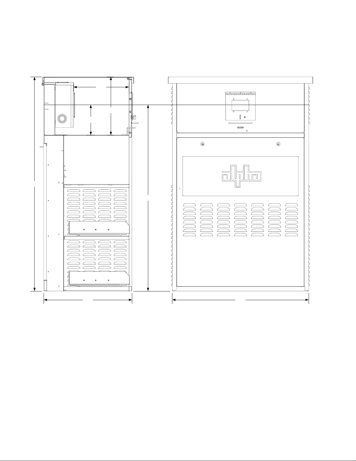
13.2"
13.6"
6.9"
50.0"
Meter Center line
43.5"
32.0"20.5"
Fig 1-3, UPE-M8 Dimensions
8 031-145-C0-002 Rev. B
Page 9
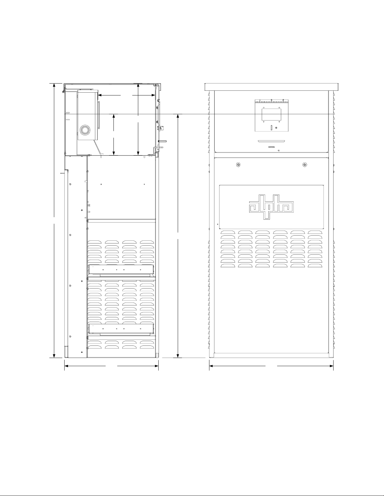
1.0 Pre-Installation, continued
1.1 Introduction, continued
12.1"
15.08"
8.5"
Meter Center Line
57.38"
50.8"
19.7" 26.0"
Fig 1-4, UPE-M6 Dimensions
9031-145-C0-002 Rev . B
Page 10
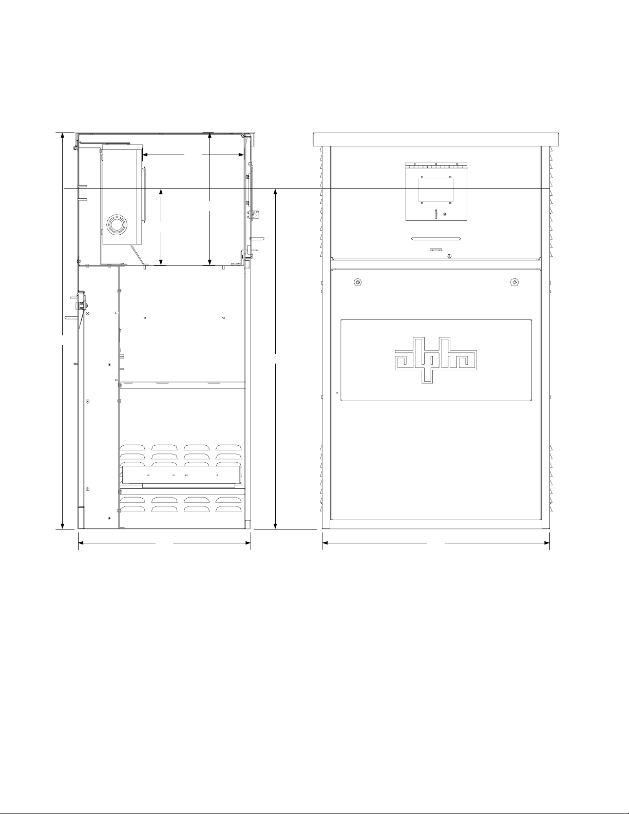
1.0 Pre-Installation, continued
1.1 Introduction, continued
12.1"
15.08"
8.4"
45.0"
Meter Center Line
38.5"
19.7" 26.0"
Fig 1-5, UPE-M3 Dimensions
10 031-145-C0-002 Rev. B
Page 11

1.0 Pre-Installation, continued
1.2 Inner Tray Layout
SPI
XM Output
Upper Tray
UPE-M8
Battery Pack
Cable
AC Power
Cord
XMS2 Powe r
Supply
UPE-M3, 6
Battery Pack
T op Tray
Bottom Tray
T op Tray
3A
3A
4A
3B
4B
Remote Temp
Sensor
2A
1A
1A
Remote Temp
Sensor
2A
1B
2B
Bottom Tray
3B
Fig. 1-6, Inner Trays
2B
1B
11031-145-C0-002 Rev. B
Page 12

2.0 Site Preparation
2.1 Site Considerations
The following points must be considered when choosing a location for the enclosure installation:
• Plan the site so the enclosure will receive good air flow. If possible, in areas of extreme heat,
position the enclosure so it is shaded from the afternoon sun.
• In areas of prevailing winds, locate the enclosure so the back of the cabinet faces the wind
instead of the sides. This will reduce the buildup of sand or snow against the enclosure’s air
vents.
• In areas of potential flooding, locate the installation above the 100-year flood plain .
• Place the enclosure where it will be free of obstructions and allows easy access to the doors
for service or equipment access. For ventilation and maintenance, allow a minimum of 36
inches in the front and rear of the enclosure.
• Place the enclosure well away from ground level sources of forced water, such as underground
sprinkler systems or direct roadway splash.
• The concrete pad drawing provided in this manual contains the required mounting details,
including electrical service and cable plant entrances.
• For ease of installation, lightweight polymer, high density polyethylene mounting supports
(Alpha PS Series) are available from Alpha T echnologies for UPE-M series enclosures.
• A vapor barrier material (such as 30 lb. felt, neoprene pond liner, or heavy grade tar paper)
should extend at least six inches in all directions around the perimeter of the enclosure. It can
be trimmed closer to the enclosure after installation.
• Install batteries only after the unit is on site and secured to the pad. Transporting the unit with
installed batteries may cause a short circuit, fire, explosion, and/or damage to the battery
pack, enclosure or installed equipment. Damage caused by improperly shipping or transporting
a unit with installed batteries is not covered under warranty.
• The batteries used in this application may vary slightly depending upon optional configurations,
battery types, or customer requirements. The batteries are typically valve-regulated gelledelectrolyte, such as the AlphaCell. If a battery is found damaged, refer to the battery
manufacturer's documentation regarding the safe handling of the battery .
12 031-145-C0-002 Rev. B
Page 13

2.0 Site Preparation, continued
2.2 Enclosure Pedestal Support
The polymer pedestal support system provides a stable foundation for UPE-M series enclosure
installations.
3/8" Bolt
Lock Washer
Flat Washer
Utility Entrance
CATV Entrance
Enclosu re mount in g bolt s
provided by customer
Cover bolts provided
with PS-1 Pedestal
18.00"
24.13"
3.00"
27.25"
31.75"
Fig. 2-1, Pedestal Support (PS-1) Dimensions
Alpha P/N 744-006-20
35.63"
38.75"
43.50"
PS-1
Pedestal
Support
13031-145-C0-002 Rev. B
Page 14

2.0 Site Preparation, continued
2.3 Pad Fabrication
3/8" Nut
Lock Washer
Flat Washer
Conduit should pass thr ou g h
concrete pad 6 inches to either
side of the center line and in line
with the rear mounting studs
12"
14"
Concrete Pad with 3/8" Moun ting Stu ds.
(All hardware customer supplied)
Note: UPE-M3, 6, and 8
have the same mounting
stud arrangement
36"
24"
48"
Consult local utility codes for
concrete pad requirements.
4"
Fig. 2-2, Concrete Pad Dimensions
14 031-145-C0-002 Rev. B
Page 15

2.0 Site Preparation, continued
2.4 Enclosure Grounding
Alpha Technologies recommends using the grounding method illustrated below. The grounding
method for a particular site is depends on soil type, available space, local codes, National Electric
Code (NEC) requirements, and other site-specific characteristics.
Alpha T echnologies recommends a minimum of five ohms ground resistance between the enclosure
and ground rods, but resistance shall not exceed 25 ohms, in accordance with IEEE 1 100-1999
(Powering and Grounding Electronic Equipment).
Alpha T echnologies assumes no responsibility or liability for failure of the inst aller to comply with
the requirements of all applicable local and national codes. Where allowed, exothermic welding
may be used as an alternative to Burndy clamps and connectors.
Connection made with Burndy connector
(P/N YGHR58C2W-3 or equivalent)
Terminate at enclosure ground
)
.
n
i
m
(
'
4
2
2
Terminate at service
entrance ground
#6 AWG
Enclosure
Footprint
1
#2 AWG
Two 8' ground rods 6' apart (min.)
Note: May require additional ground rods
to meet NEC minimum grounding
standard (25 ohms or less).
Fig. 2-3, Enclosure Grounding
Service Grounding (required)
1
#6 bare copper wire from Service Neutral / Ground Bar with 2 ground rods located 6' apart.
Lightning Protection (optional)
2
1/2" x 8' copper ground rod, four places, driven about two feet (typical) from the corners of the
pad.
Connection made wit h Burndy conne ct or
(P/N YGHP58C2W-2TN or equivalent)
3
#6 bare copper wire loop terminated to each ground rod and buried 30 inches (min.) below grade.
3
Corrosion-proof connections (25-year life span) and hardware suitable for direct burial must be
used.
#6 bare copper wire from loop to the enclosure.
4
15031-145-C0-002 Rev. B
Page 16

3.0 Installation
3.1 Enclosure Installation
Tools Needed:
• Ratchet set with 6” extension
• Vapor Barrier
• Utility Knife
Procedure:
A 25-year continuous vapor barrier must be used between the enclosure and pad to prevent moisture
ingress and possible corrosion caused by metal to concrete contact. The vapor barrier material
(such as 30 lb. felt, neoprene pond liner, or heavy grade tar p aper) should initially extend at least
six inches in all directions around the perimeter of the enclosure.
1. Unwrap the enclosure and inspect the contents. If items are missing or damaged, contact
Alpha T echnologies and the shipper immediately .
2. Place the vapor barrier material on the pad.
3. Unbolt the enclosure from the shipping pallet.
4. Using an appropriate lifting device, lift the enclosure off the shipping pallet and place over the
mounting studs on the pad.
5. Secure the enclosure to the pad using four (two front, two rear) stainless steel flat washers,
lock washers, and nuts.
6. Trim the vapor barrier material with an appropriate cutting tool.
Front
Rear
Fig. 3-1, Enclosure Mounting Holes
16 031-145-C0-002 Rev. B
Page 17

3.0 Installation, continued
3. 2 Utility Powering
• The XM2 Power Supplies are powered by either 120VAC or 240V AC (120/120 grounded neutral) att ached to
an internal service entrance. The size of the service conductors must be based upon the actual size of the
utility service, and must comply with applicable electrical code requirements.
• Proper grounding is critical. A qualified electrician should verify that grounding complies with applicable
electrical codes. All applicable codes must be adhered to when installing a system, pouring concrete, or
placing a preformed pad. Local codes supersede any procedures outlined in this document.
• The following should be performed only by qualified service personnel and in compliance with local electrical
codes. Verify electrical codes prior to inst allation. Codes may vary and contain specific conduit and wire
sizes for connection to the service entrance. Connection to utility power must be approved by the local utility
before installing the power supply .
• All mounting hardware should be stainless or galvanized, depending on local environmental
conditions. Use of improper hardware may cause corrosion not covered under warranty.
• Soil conditions vary and may affect the integrity of the p ad. Alpha Technologies recommends that
proper steps be taken to ensure that the soil supporting the pad is stable. Improper installation of
the pad may cause uneven settling or cracking not covered under warranty.
17031-145-C0-002 Rev. B
Page 18

3.0 Installation, continued
3.2 Utility Powering, continued
Line
Neutral
Neutral Wire
Line
Fused
Disconnect Box
Neutral
Load
Load
Neutral Wire
D
Line
Neutral
Line
N
OFF OFF
ONO
BBX
Utility Raceway CATV Raceway
Fig. 3-2, 65K-AIR Enclosure
(Rear View)
Fig. 3-3, 10K-AIR Enclosure
(Rear View)
18 031-145-C0-002 Rev. B
Page 19

3.0 Installation, continued
3.2 Utility Powering, continued
120VAC without
Test Bypass Block
120VAC with
Test Bypass Block
240/120VAC without
Test Bypass Block
To FB X/BBX
To FBX/BBX
From Utility
From Utility
240VAC without
Test Bypass Block
To FBX/BBX
To FBX/BBX
Fig. 3-4, Meter Base Configurations
From Utility
From Utility
19031-145-C0-002 Rev. B
Page 20

3.0 Installation, continued
3.2 Utility Powering, continued
240/120VAC with
Test Bypass Block
To FBX/BBX
240VAC with
Test Bypass Block
To FBX/BBX
208VAC with 5th Jaw
and Test Bypass Blocks
From Utility
From Utility
To FBX/BBX
From Utility
Neutral T e rminal Bloc k
Fig. 3-5, Meter Base Configurations
20 031-145-C0-002 Rev. B
Page 21

3.0 Installation, continued
3.2 Utility Powering, continued
120VAC
Single Receptacle
Fuse Part Numbers:
Alpha: 460-192-10
Bussman: FNR-R-20
L1
120VAC/240VAC
120VAC
Dual Receptacle
Single Fuse
120VAC
Dual Receptacle
Dual Fuse
L1 L2
L1
L1 L2
240VAC
120VAC
Fig. 3-6, Fuse/Receptacle Configurations for 65K-AIR Enclosures
21031-145-C0-002 Rev. B
Page 22

3.0 Installation, continued
3.2 Utility Powering, continued
120VAC
Single Receptacle
120VAC/240VAC
From Meter Compartment
From Meter Compartment
240VAC
120VAC
120VAC
Dual Receptacle
Single Breaker
120VAC
Dual Receptacle
Dual Breaker
From Meter Compartment
From Meter Compartment
Fig. 3-7, Fuse/Receptacle Configurations for St andard Enclosures
22 031-145-C0-002 Rev. B
Page 23

3.0 Installation, continued
3.3 Service Power Inserter
Mount the SPI box(es) on the back wall of
the Power Supply compartment.
1. Remove the two screws on the face of
the SPI and lift off the cover to gain
access to the seizure screw assembly .
Loosen the seizure screw several turns,
so the stinger will pass through the
clamp.
3, Insert the coaxial termination into the
output port on the bottom of the SPI.
Ensure that the stinger goes through
the seizure screw assembly. Tighten
the coaxial termination.
4. Tighten the seizure screw to 35 inchpounds. Replace the SPI cover and
screws. Ensure the switch on the top
or the SPI is in the ON position, the
AUX position is used only when an
alternate power source is connected to
the Jones connector on the top of the
SPI.
Enclosure
Output
Port
Wall
Coaxial Termination
Seizure Screw
Assembly
Jones Connector
Service
Power
Inserter
Seizure Screw
Assembly
Fig. 3-8, Removing SPI Cover
Stinger
Side View of SPI Case
Stinger
Circuit Board
Fig. 3-9, Connecting Coax to SPI Output Port
To prevent arcing, the center conductor (stinger) of the coaxial termination must go fully inside the
seizure screw assembly. Tighten to 35 inch-pounds.
23031-145-C0-002 Rev. B
Page 24

3.0 Installation, continued
3.4 Battery Installation
Battery Identification
Each battery contains a date code usually located on a sticker near the center of the battery or
stamped in white ink near the POS terminal. This date code must be recorded in the battery’s
maintenance log. If batteries, other than those marketed by Alpha are used, consult the battery’ s
manufacturers’ documentation for date code type and placement.
DANGER/POISON
SHIELD EYES EXPLOSIVE GASES
CAN CAUSE BLINDNESS OR INJURY
NO SPARKS, FLAMES, OR SMOKING
SULFURIC ACID CAN CAUSE
BLINDNESS OR SEVERE BURNS
FLUSH E YE S IMMEDIAT E LY WITH WATER
GET MEDICAL HELP FAST. KEEP OUT OF REACH OF CHILDREN
CALIF. PROPOSITION 65
WARNING
Battery posts, terminals
and related accessories
contain lead and lead
compounds, c hemic als
known to the s t ate of Calif.
to cause cancer and
reproduct ive harm. Wash
hands after handl ing .
MMYY
Battery Date Cod e
located in this box
(0103 = Jan. 2003)
Battery T erminal Connections
The accompanying drawings are for illustrative purposes only. Various types of batteries with
different mounting styles and hardware may be shipped with the system. Always refer to the
battery manufacturers’ specifications for correct mounting hardware and torque requirements.
During maintenance procedures, refer to the manufacturers' specifications for the maintenance
torque requirements.
For AlphaCell batteries, use 65 inch-pounds upon installation, then re-torque to 50 inch-pounds.
Mounting hardware requirements may vary between battery manufacturers. Use only the hardware
recommended by your particular battery manufacturer.
Battery Cable and
Crimp Connector to
Battery Post
3/8" Spacer
Flat Washer
Lock Washer
Nut
Fuse
Next Battery
Fig. 3-10, Battery Terminal Assembly
24 031-145-C0-002 Rev. B
Page 25

3.0 Installation, continued
3.4 Battery Installation, continued
Tools Needed:
Two 7/16” open end wrenches
Procedure:
This section is for reference only , follow instructions included in the battery cable kit. This procedure
covers the UPE-M3 (one tray), and the UPE-M6 and UPE-M8 (two trays).
1. Release the latch on the left slide. Pull the (lower) tray out until it reaches the stops.
2. Install three or four batteries as shown in Fig. 3-1 1 (following page). Wire in accordance with
the diagram included in the Battery Cable Kit.
3. Disengage the hold-open latch and slide the battery tray into the enclosure.
4. Repeat for the center tray (UPE-M6 and UPE-M8 only).
25031-145-C0-002 Rev. B
Page 26

3.0 Installation, continued
3.4 Battery Installation, continued
To XM2 Power Supply
Upper Tray
or UPE-M3
Lower Tray
To XM2 Power Supply
3A
Remote
Temp
Sensor (RTS)
Fuse
Fuse
1A2A3A
UPE-M3 and UPE-M6
Battery Packs
1B2B3B
1A
Upper Tray
(UB)
4A
2A
Fuse
Remote
Temp
Sensor (RTS)
UPE-M8
Battery Pack
3B
1B
Lower Tray
(LB)
4B
Fig. 3-1 1, Battery Pack
26 031-145-C0-002 Rev. B
2B
Fuse
Page 27

3.0 Installation, continued
3.5 Power Supply Installation
Tools Needed:
1 1/32” nut driver (see step 2)
Procedure:
1. The upper tray of the enclosure has five dimples that line up with the feet of the XMS2 power
supply . The feet of the power supply must rest in these dimples so the ventilation snorkel on
the front cover aligns with the fan to form a seal when the door is closed.
2. If a power supply other than Alpha’s XMS2 is used, remove the four (4) #8-32 Keps nuts
holding the ventilation snorkel to the inside of the front door and remove the snorkel.
3. Place the power supply on the top tray.
KEPS
Nuts
27031-145-C0-002 Rev. B
Page 28

3.0 Installation, continued
3.6 Power Supply Connections
1. Verify that the Battery Circuit Breaker is in the OFF position. Connect the red and black cable
from the battery pack to the Battery Input connection on the front of the power supply .
2. Connect the black and white wire leading from the Service Power Inserter (SPI) to the plug
labeled Output 1A on the front of the power supply. If a second SPI is installed, connect it to
Output 2.
3. Verify that the Input Breaker in the Service Entrance Panel is in the OFF position. Plug the
power supply’s AC power cord into the Input Power Panel (IPP) or Breaker Duplex Option
(BDO).
Battery Circuit
Breaker
Battery Input
from Battery Pack
Power Supply Output to SPI
Fig. 3-12, Battery and Output Power Connections
OFF
28 031-145-C0-002 Rev. B
Page 29

3.0 Installation, continued
3. 7 Lightning Arrester (LA-P+) Option
The Lightning Arrester option is available in 120V AC and 240V AC, and is inst alled by plugging into
an Input Power Panel (IPP) or Breaker Duplex Option (BDO). The unit is operating properly when
the green LED is lit.
3. 8 LRI Option
Green LED
The LRI lamp assembly can be inserted into one of four knockouts in the enclosure walls (see
below). Remove the nut and washer from the base and insert the base into the knockout from the
outside. Replace the nut and washer , and tighten.
Enclosure
Wall
Black Connector
Red Connector
Ensure contact snaps
over metal retainer.
Top View
Black Wire
Red Wire
Side View
Snap the plastic connector housing over the connectors as shown above, with the black housing
on the black wire. Insert the assembled connector into the LRI connection on the front of the power
supply .
LRI Knockouts
29031-145-C0-002 Rev. B
Page 30

3.0 Installation, continued
3.9 Enclosure Cooling Fan (optional)
The cooling fan is required whenever an XM2-915 or 922 is installed in a UPE-M6 or M8 where the
average temperature of any month exceeds 95°F (35°C).
Install the optional Enclosure Cooling Fan (ECF) using four #8-32 Keps nuts (included) on existing
threaded studs (upper left corner for the UPE-M8, and upper right corner for UPE-M3 and UPEM6). Plug one end of the supplied “Y” cable into the output connection of the power supply , and
connect the other end to the wire leading from the SPI. Connect the fuse end to the fan wire kit.
The cooling fan is thermostatically controlled to turn on at 1 10°F (43°C), and of f at 80°F (27°C).
Replace fuse only with 1/4” X 1-1/4”, 5A, 250V (Alpha P/N 460-025-10).
Keps Nuts
Fan KitStuds
30 031-145-C0-002 Rev. B
Page 31

Alpha T echnologies
Power
®
Alpha T echnologies
3767 Alpha Way
Bellingham, WA 98226
USA
Tel: +1(360) 647-2360
Fax: +1(360) 671-4936
Web: www.alpha.com
Alpha Technologies Ltd.
4084 McConnell Court
Burnaby, BC, V5A 3N7
CANADA
Tel: +1(604) 430-1476
Fax: +1(604) 430-8908
Alpha T echnologies
Europe Ltd.
Cartel Business Estate
Edinburgh Way
Harlow, Essex CM20 2TT
UNITED KINGDOM
Tel: +44-1279-4221 10
Fax: +44-1279-423355
Alpha T echnologies
Hansastrasse 8
D-91126 Schwabach
GERMANY
T el: +49-9122-79889-0
Fax: +49-9122-79889-21
Alphatec
339 St. Andrews Street
Suite 101
Andrea Chambers
Limassol, Cyprus
CYPRUS
T el: +357-25-375675
Fax: +357-25-359595
Alpha T echnologies
Unit R5-R7 Regents Park Estate
Corner Park Rd and Prince’s Rd East
Regents Park, NSW 2143
AUSTRALIA
T el: +61-2-9722-3320
Fax: +61-2-9722-3321
Copyright © 2004 Alpha T echnologies, Inc. All rights reserved. Alpha is a registered trademark of Alpha Technologies. 031-145-C0-002 Rev . B .
Due to continuing product improvements, Alpha reserves the right to change specifications without notice.
 Loading...