

Page 1
Installation and Operation Manual
UPE-3L and UPE-6L Enclosures
Effective: January, 2003
®
Page 2

Alpha Technologies
Power
®
Page 3

UPE-3L, UPE-6L
Enclosure Installation Manual
031-178-C0-001, Rev. A
Effective Date: January, 2003
Copyright© 2003
Alpha Technologies, Inc.
NOTE: Alpha denies responsibility for any damage or injury involving its
enclosures, power supplies, generators, batteries, or other
hardware when used for an unintended purpose, installed or
operated in an unapproved manner, or improperly maintained.
NOTE: Photographs contained in this manual are for illustrative purposes
only. These photographs may not exactly match your installation.
NOTE: Review the drawings and illustrations contained in this manual
before proceeding. If there are questions regarding the safe
operation of this powering system, please contact Alpha
Technologies or your nearest Alpha representative.
Contacting Alpha Technologies:
For general product information and customer service
1-800-863-3930
(7:00 AM to 5:00 PM Pacific Time )
For complete technical support
1-800-863-3364
(7:00 AM to 5:00 PM Pacific Time, or 24/7 emergency support)
Page 4

Preface
Series
UPE
Preface Topic Page
Overview 4
About This Manual 4
Table of Contents 5
List of Figures 5
Product Safety 6
Battery Safety Notes 9
Installation Notes 10
Enclosures
Overview: The purpose of this UPE Series Enclosure Installation
Manual is to provide a high-level overview of the system
and to detail the installation procedure for the
enclosures.
Audience: This manual intended for the installers of the system.
About this manual:
Contents: This Installation Manual is comprised of two sections.
Section 1 Pre-Installation. This section describes site
selection, pad layout, and enclosure grounding.
Section 2 Installation. This section describes the installation
of the enclosure to the pad, and the installation of
batteries and power supplies
4
031-178-C0-001 Rev. A
Page 5

Series
UPE
SECTION ONE Pre-Installation
1.1 Site considerations ................................................................................. 10
1.2 Enclosure Dimensions ........................................................................... 11
1.3 Pedestal support .................................................................................... 13
1.4 Enclosure Grounding ............................................................................. 15
SECTION TWO Installation
2.1 Enclosure Protection .............................................................................. 17
2.2 Transportation and Lifting ....................................................................... 18
2.3 Enclosure Installation ............................................................................. 19
2.4 Utility Power Connection ........................................................................ 20
2.5 Power Supply Placement ....................................................................... 27
2.6 Battery Installation .................................................................................. 27
2.7 Battery Temperature Sensor .................................................................. 31
2.8 Lightning Arrester Option ....................................................................... 32
2.9 Battery Heater Mat and LRI-ACI Lamp Options ..................................... 33
2.10 Enclosure Door Tamper Switch / Rain Deflector Options ...................... 34
Enclosures
Table of Contents
Preface
List of Figures
Fig. 1-1 UPE-3L Enclosure Dimensions....................................................................... 11
Fig. 1-2 UPE-6L Enclosure Dimensions....................................................................... 12
Fig. 1-3 Typical Pedestal Configurations ...................................................................... 13
Fig. 1-4 Typical Pedestal Installation ........................................................................... 14
Fig. 1-5 Enclosure Grounding ...................................................................................... 16
Fig. 2-1 Post placement .............................................................................................. 17
Fig. 2-2 External Coax Raceway ................................................................................. 20
Fig. 2-3 Service Entrance Option ................................................................................ 22
Fig. 2-4 Typical Service Entrance Wiring ..................................................................... 23
Fig. 2-5 Breaker-Quad-Option Wiring ........................................................................... 24
Fig. 2-6 120 and 240VAC UL Wiring (030-051-C7-A) .................................................... 25
Fig. 2-7 Battery Hazard Warning Label ......................................................................... 27
Fig. 2-8 Battery Terminal Connections ......................................................................... 28
Fig. 2-9 UPE-3L Battery placement ............................................................................. 30
Fig. 2-10 UPE-6L Battery placement ............................................................................. 30
Fig. 2-11 RTS Placement .............................................................................................. 31
Fig. 2-12 LAP Plus ........................................................................................................ 32
Fig. 2-13 Surge Arrester ................................................................................................ 32
Fig. 2-14 ACI/LRI Wiring ................................................................................................ 33
Fig. 2-15 Tamper Switch Wiring ..................................................................................... 34
031-178-C0-001 Rev. A
5
Page 6
Preface
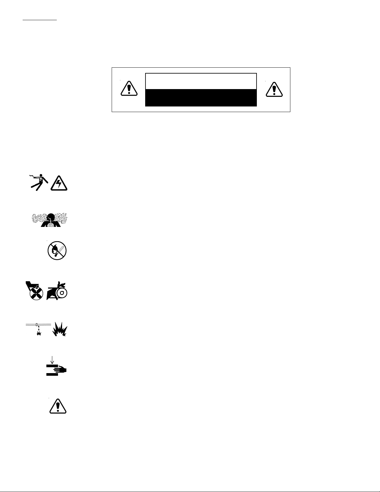
Important Safety Instructions Contained in This
Manual
CAUTION
HAZARDOUS CONDITION
To reduce the risk of electrical shock, injury or death caused by explosion of fuel or moving
parts, and to ensure the safe operation of this unit, the following symbols have been
placed throughout the manual. Where these symbols appear, servicing should be
performed only by qualified personnel.
DANGEROUS VO LTAGE
This symbol indicates a “dangerous voltage” exists in this area of the
product. Use caution whenever working in the area to prevent
electrical shock.
INHALATION HAZARD - DON’T BREATHE VAPORS
This symbol indicates an “inhalation hazard” exists in this area of the
product. Use caution whenever working in the area to prevent possible
inhalation of harmful (fuel or exhaust) vapors.
NO MATCHES OR OPEN FLAMES
This symbol indicates a fire or explosive hazard exists in this area of
the product. Use caution whenever working in the area to prevent
possible combustion fuel vapors.
MECHANICAL OR MOVING PARTS HAZARD
These symbols indicate the presence of a “mechanical or moving parts
hazard” in this area of the product. Use caution whenever working in
the area to prevent possible injury to the operator or service personnel.
LEAK HAZARD
This symbol indicates a “leak hazard” exists in this area of the product.
Use caution whenever working in the area to prevent and correct any
leaks detected.
CRUSH HAZARD
This symbol indicates the presence of crushing hazard in this area.
Keep hands clear of areas under extended battery trays and equipment
drawers.
ATTENTION
This symbol indicates important installation, operation or maintenance
instructions. Always follow these instructions closely.
6 031-178-C0-001 Rev. A
Page 7

Warnings
NOTE: This power supply and its associated hardware (enclosure, batteries, cabling)
Preface
A “Warning” identifies conditions and actions that pose a hazard to the user.
A “Caution” identifies conditions and actions that may damage the power
supply or associated equipment.
may contain equipment, batteries or parts which have accessible hazardous
voltage or currents.
To avoid injury
:
• This power supply and its associated hardware must be serviced by authorized personnel
only.
• The enclosure which contains the power supply and associated equipment must remain
locked at all times, except when authorized service personnel are present.
• Remove all conductive jewelry or personal equipment prior to servicing equipment, parts,
connectors, wiring, or batteries.
• Read and follow all installation, equipment grounding, usage, and service instructions
included in this manual.
• Use proper lifting techniques whenever handling equipment, parts, or batteries.
• Batteries contain dangerous voltages, currents and corrosive material. Battery installation,
maintenance, service and replacement must be performed by authorized personnel only.
• Never use uninsulated tools or other conductive materials when installing, maintaining,
servicing or replacing batteries.
• Use special caution when connecting or adjusting battery cabling. An improperly connected
battery cable or an unconnected battery cable can result in arcing, a fire, or possible
explosion.
• A battery that shows signs of cracking, leaking or swelling must be replaced immediately by
authorized personnel using a battery of identical type and rating.
• Avoid any contact with gelled or liquid emissions from a valve-regulated lead-acid (VRLA)
battery. Emissions contain dilute sulfuric acid which is harmful to the skin and eyes.
Emissions are electrolytic, which are electrically conductive and are corrosive. Follow the
Chemical Hazards notes if contact occurs.
• Do not smoke or introduce sparks in the vicinity of a battery.
7 031-178-C0-001 Rev. A
Page 8

Preface
Battery Safety Notes
Lead-acid batteries contain dangerous voltages, currents and corrosive material. Battery
installation, maintenance, service and replacement must be performed by authorized personnel
only.
Chemical Hazards
NOTE: Any gelled or liquid emissions from a Valve-Regulated lead-acid (VRLA)
battery contain dilute sulfuric acid, which is harmful to the skin and eyes.
Emissions are electrolytic, which are electrically conductive and
corrosive.
To avoid injury:
• Wear protective clothing (insulated gloves, eye protection, etc) whenever installing,
maintaining, servicing, or replacing batteries.
• If any battery emission contacts the skin, wash immediately and thoroughly with water.
Follow your company’s approved chemical exposure procedures.
• If any battery emission contacts the eye, wash immediately and thoroughly with water for
10 minutes with pure water or a special neutralizing eye wash solution and seek
immediate medical attention. Follow your company’s approved chemical exposure
procedures.
• Neutralize any spilled battery emission with the special solution contained in an approved
spill kit or with a solution of 1 lb. bicarbonate of soda to 1 gal of water. Report chemical
spill using your company’s spill reporting structure and seek medical attention if
necessary.
• Always replace batteries with those of an identical type and rating. Never install old or
untested batteries.
• Do not charge batteries in a sealed container. Each individual battery should have at least
0.5 inches of space between it and all surrounding surfaces to allow for convection
cooling.
• All battery compartments must have adequate ventilation to prevent an accumulation of
potentially dangerous gas.
8 031-178-C0-001 Rev. A
Page 9

Important Installation Notes
The system must be installed ONLY by qualified service personnel.
Consult local utility codes for additional cabinet grounding and utility requirements.
ALPHA TECHNOLOGIES is not responsible for broken welds or other damage to the
cabinet caused by improper installation.
All dimensions are given in inches.
For further information regarding this installation, contact ALPHA TECHNOLOGIES or your
nearest ALPHA representative.
For general product information and Customer Service
7:00AM to 5:00PM Pacific Time
1-800-863-3930
Preface
To obtain complete Technical Support,
7:00AM to 5:00PM Pacific Time
or
For after-hours Emergency support
7 days per week, 24 hours a day
1-800-863-3364
NOTE:
Alpha Technologies’ products are subject to change
through continual improvement processes. Therefore,
specifications and/or design layouts may vary slightly
from descriptions included in this manual. Updates to the
manual will be issued when changes affect form, fit or
function.
Save these instructions for future reference
9 031-178-C0-001 Rev. A
Page 10

1. Pre-Installation
1.1 Site considerations
The site must be planned so that the enclosure will receive good air flow. If
possible, in areas of extreme heat, it is best to position the enclosure so that it
will be shaded from the afternoon sun. If no shade is available, a factory installed
fan kit is highly recommended. In areas of prevailing winds, it is best that the
enclosure be located so that the sides of the cabinet face the winds instead of the
doors. This will greatly reduce the buildup of sand or snow against the enclosure’s
air vents.
In areas of potential flooding, the geographical site and concrete pad must be
located above the 100 year flood plain.
The enclosure must be placed where it will be free of obstructions, allowing
easy access to the doors for service or equipment access. For ventilation and
maintenance, allow a minimum space of 36 inches in the front and 36 inches in
the rear, between the enclosure and other solid structures.
Place the enclosure well away from sources of forced water, such as
underground sprinkler systems and direct roadway splash.
The concrete pad drawing provided in this manual contains all of the required
mounting details, including electrical service and cable plant entrances.
For ease of installation, lightweight polymer concrete pads are available from
Alpha Technologies for all UPE series enclosures.
The vapor barrier material (such as 30 lb. felt, neoprene pond liner, or heavy
grade tar paper) must initially extend at least 6" in all directions around the
perimeter of the enclosure and be trimmed closer to the enclosure. Contact local
utilities, building maintenance departments and cable/pipe locating services to
ensure that this installation does not interfere with existing utility or building
cables or piping. It is the responsibility of the installer/owner to position and
protect the enclosure to minimize/prevent traffic related hazards.
WARNING: Never transport the unit with batteries installed.
Batteries must ONLY be installed after the unit is
transported to the site and secured to the pad.
Transporting the unit with batteries installed may
cause a short circuit, fire, explosion, and/or damage
to the battery pack, enclosure and installed
equipment. Damage caused by improper shipping or
transporting a unit with batteries installed is not
covered by the warranty.
The batteries used in this application may vary slightly depending upon
optional configurations, battery types, or customer requirements. The batteries are
typically gelled-electrolyte, valve-regulated such as the Alpha Cell. Should a
battery be found damaged, refer to the battery manufacturer's documentation
regarding the safe handling of the battery.
10 031-178-C0-001 Rev. A
Page 11
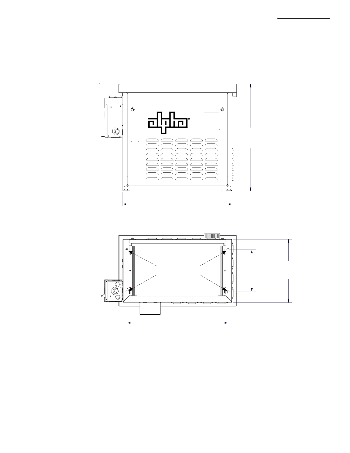
1.2 Enclosure dimensions
1. Pre-Installation
25.5 in.
647 mm
26 in.
660 mm
(front view)
Mounting Holes
24 in.
609 mm
(bottom View)
Figure 1-1 UPE-3L Enclosure Dimensions
10 in.
254 mm
15 in.
381 mm
11 031-178-C0-001 Rev. A
Page 12
1. Pre-Installation
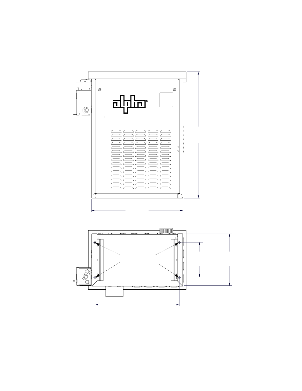
1.2 Enclosure dimensions,
continued
36 in.
914 mm
26 in.
660 mm
(front view)
Mounting Holes
254 mm
24 in.
609 mm
(bottom View)
Figure 1-2 UPE-6L Enclosure Dimensions
10 in.
15 in.
381 mm
12 031-178-C0-001 Rev. A
Page 13

1. Pre-Installation
1.3 Precast Enclosure Pedestal Support
Alpha’s precast pedestal support system provides a quick, one-step solution for installing
the UPE series enclosures.
Contact Alpha Technologies Customer Service (1-800-863-3930) to determine which
Pedestal Support is needed for your installation.
Cover
Alpha P/N 564-911-10
PS6 Pedestal
Alpha P/N 745-324-20
Drill here for
extern al load
center, if used.
Drill here for
extern al servi ce
entrance, if used.
Fig. 1-3 Typical Pedestal Configurations
Drill here for UP E-6
ECR
Drill here for UP E-3
ECR
PS-6 XL Pedestal
Alpha P/N 745-324-21
13 031-178-C0-001 Rev. A
Page 14

1. Pre-Installation
1.3 Precast Enclosure Pedestal Support,
continued
For detailed installation instructions, refer to the Manufacturer’s Installation
Documentation included with the Pedestal Support Package.
UTILITY
UNDISTURBED GROUND
Fig. 1-4 Typical Pedestal Installation
PRECAST PAD
PEDESTAL SUPPORT
6 to 12 Inches
Compacted Gravel
GRADE
BACK-FILL
OUTPUT SWEEP
14 031-178-C0-001 Rev. A
Page 15

1. Pre-Installation
1.4 Enclosure Grounding
In order to provide a ready, reliable source of backup power it is necessary to establish a
grounding system that not only provides for the safety of the service personnel responsible for
its operation and maintenance, but also facilitates the proper operation and protection of the
equipment within the network. Such a grounding system will provide protection with respect to
operator safety, system communication, and equipment protection.
Safety Ground
The safety ground is a two-part system. The first part is a return path for stray current back to
the input breaker, and the second is a return path from the Alpha enclosure to a second ground
rod.
Typically, the safety, or utility ground, provides a return path to the input breaker or fuse panel
by means of a connection to an appropriate driven ground rod at the base of the power pole.
This path must meet National Electric Code (NEC) as well as local codes to ensure the breaker
will open, preventing unwanted current flow from posing a hazard to service personnel.
The second part of the safety ground arrangement is the ground path between the Alpha
enclosure and a second ground rod located at least 6 feet away from the driven ground rod at
the power pole. The second ground rod and enclosure are connected via an AWG #6 solid
copper wire buried at a depth of 8-12 inches. The wire is connected to the cabinet by means of
a ground lug on the back of the cabinet (for pole-mounted enclosures), or to a ground lug inside
the cabinet (for ground-mounted enclosures), and connected to the ground rod by means of a
listed grounding clamp suitable for direct burial, or exothermic weld. Normally it is specified that
the impedance of this ground can be no greater than 25 ohms at 60 Hertz. If, however, dual
ground rods are installed approximately eight feet apart, it is not necessary to measure the
impedance of the ground rods to meet the maximum 25 ohms specification—it is assumed that
the impedance specification is met.
Signal Ground
For proper operation, the Service Power Inserter must be securely grounded to the enclosure
chassis. This is of particular importance in systems utilizing an external status monitoring
transponder. The transponder chassis is grounded via a separate ground wire to the SPI case.
For systems utilizing an embedded transponder, the ground connection is made either through a
separate chassis ground block, or by means of the internal mounting hardware which then
grounds the transponder through the XM Series 2 Power Supply.
Strike (Lightning) Ground
Lightning strikes, grid switching, or other aberrations on the power line all have the potential to
cause “fast rise-time currents” which can cause damage to the powering system. Without a lowimpedance path to ground, the current, while traveling through wires of varying impedance, can
produce high voltages which will damage the powering equipment. The most viable method
available to protect the system from damage is to divert these unwanted “fast rise-time
currents” along a low-impedance path to ground. A low-impedance path to ground will prevent
these currents from reaching high voltage levels and posing a threat to equipment. The singlepoint grounding system provides a low-impedance path to ground, and the key to its success is
the proper bonding of the ground rods, so the components of the grounding system appear as a
single point of uniform impedance.
Low impedance grounding is not only critical for the proper operation of the cable system, but
also is mandatory for personnel safety.
15 031-178-C0-001 Rev. A
Page 16

1. Pre-Installation
1.4 Enclosure Grounding
NOTE: Alpha Technologies recommends using the grounding method illustrated below. The
grounding method for a particular site will be dependant upon soil type, available space,
local codes, NEC (National Electric Code), and other site-specific characteristics.
It is the responsibility of the installer to ensure the requirements of all applicable
national and local codes are met. Alpha Technologies assumes no responsibility or
liability for failure of the installer to comply with the requirements of all applicable
local and national codes. Where allowed, exothermic welding may be used as an
alternative to Burndy clamps and connectors.
Connection made with Burndy connector
(P/N YGH R58C2W-3 or equivalent)
Ter minate at enc losure grou nd
Term inate at s ervice
entran ce ground
#6 AW G
8' ground rods 6' apart minimum.
Note: M ay require add itional gr ound rods t o meet
NEC minimum gr ounding standard (25 Ohms or
less).
Service Grounding (required)
4
Enclosure Footprint
1
#2 AW G
Connection made with Burndy connector
(P/N YGHP58C2W -2TN or equivalent)
2
Fig. 1-5 Enclosure Grounding
t
e
e
f
2
)
n
i
m
(
3
1
#6 bare copper wire from Service Neutral / Ground Bar with 2 ground rods located 6'
apart.
Lightning Protection (optional)
2
3
1/2" x 8' copper ground rod, four places, driven about 2 feet (typical) from the corners
of the pad.
#6 bare copper wire loop terminated to each ground rod and buried below grade 30
inches min. Corrosion-proof connections (25+ year life-span) and hardware suitable
for direct burial MUST be used.
4
#6 bare copper wire from loop to the enclosure
16 031-178-C0-001 Rev. A
Page 17

2.1 Enclosure Protection
Alpha Technologies, Inc. cannot anticipate all of the ways a vehicle may
potentially threaten an installed system or the specific type of protection that is
appropriate for a particular location. The determination of the threat to the
equipment and the means of protection are the responsibility of the end user of the
equipment and the authority having jurisdiction. The following installation drawing
for Alpha’s Standby Power systems are general recommendations and not intended
to be a specific guideline for protecting the equipment. The numbers of Bollard
posts (or other protection devices) depend upon equipment locations, site surveys,
traffic patterns and local codes.
2. Installation
PAD
POSTS
10' Min.
Sprinkler
Head
SIDEW ALK
Fig. 2-1 Post placement
17 031-178-C0-001 Rev. A
Page 18

2. Installation
2.2 Transportation and Lifting
A safe means of transportation to the site and a safe procedure for unloading the enclosure is
necessary. At least two installation personnel are required to place the enclosures on the pad.
Installation team must assess the transport path for all obstructions. An obstruction free path
should be selected for transport. Use safe lifting practices.
Approximate shipping weight:
Enclosure
UPE-3L 56 Pounds
UPE-6L 68 Pounds
Approximate
Shipping Weight
NOTE: Enclosure must always remain in the upright position during the
shipping, storage and installation process. Damage may result
from enclosure being shipped or stored on its side.
NOTE: Electronic modules, batteries or other components must not be
installed until the enclosure is securely set in place at its permanent
location.
NOTE: DO NOT lift the enclosure by the cover, unless empty.
18 031-178-C0-001 Rev. A
Page 19

2.3 Enclosure Installation
2.3.1 Attaching enclosure to the Pedestal Support or Pad
Tools Required:
Ratchet set with 6” extension.
Vapor Barrier
Utility Knife
Procedure:
2. Installation
NOTE: A 25+ year
between the enclosure and pad to prevent moisture
ingress and possible corrosion caused by metal to
concrete contact. The vapor barrier material (such as
30 lb. felt, neoprene pond liner, or heavy grade tar
paper) should initially extended at least 6" in all
directions around the perimeter of the enclosure and
later be trimmed closer to the enclosure.
1. Unwrap the enclosure and inspect the contents. If items are
missing or damaged, contact Alpha Technologies and the shipper
immediately.
2. Place the vapor barrier material on the pad.
3. Unbolt the enclosure from the shipping pallet.
4. With no less than 2 installation personnel, lift the enclosure off the
shipping pallet, and place over the mounting studs on the pad.
5. Secure the enclosure to the pad using the hardware supplied
with the Precast Pad or Pedestal Support.
6. Trim the vapor barrier material.
continuous vapor barrier
must be used
19 031-178-C0-001 Rev. A
Page 20

2. Installation
2.3 Enclosure Installation,
2.3.2 Attaching the External Coax Raceway
The external coax raceway is held in place by two tabs at the bottom of the raceway
that fit into slots at the bottom of the enclosure, and a wingnut at the top.
continued
Wing-Nut
SPI
Fig. 2-2 External Coax Raceway
SPI
External Coax
Raceway
Rear wall of UPE
Retaining Tab
20 031-178-C0-001 Rev. A
Page 21

2. Installation
2.4 Utility Power Connection
CAUTION: The “Utility Power Connection” procedure must ONLY be performed by qualified
service personnel and in compliance with local electrical codes and common
safety practices. Connection to utility power must be approved by the local
utility before installing the power supply.
NOTE: CSA and NEC require that a service disconnect switch be provided
by the installer and be connected between the power source and the ALPHA
power supply. Connection to the power supply must include an appropriate
service entrance weather head.
Wiring the Utility Service
Utility power enters the enclosure through the side or bottom of the UPE. The enclosure
accepts a standard electrical fitting. The UPE Series can be equipped with an optional circuit
breaker assembly located in the enclosure’s module compartment.
NOTE: A “high-magnetic” or HACR (Heating, Air Conditioning, Refrigeration) circuit
breaker must be used in order to accommodate the high-inrush currents
normally associated with the start-up of ferroresonant transformers
(400 Amp, no-trip, first-half cycle). Do not replace this circuit breaker with a
conventional service entrance circuit breaker. Alpha recommends Square D
circuit breakers ONLY, because of increased reliability in this powering
application.
240VAC Service (XM Series 2 915-240 Power Supply for UPE-3L and UPE-6L): Enclosures used
with the XM Series 2 915-240 is equipped with one or two 240VAC duplex receptacles to provide
power to the power supply and peripheral equipment. The receptacle, NEMA 6-15R, is protected
by a single, 2-pole, common trip 15 Amp circuit breaker located inside the service entrance.
Wiring is typically 14AWG per NEC code, a grounding clamp, located on the enclosure, facilitates
dedicated grounding.
120VAC 20A Service (XM Series 2 915-120 Power Supply):
Enclosures used with the XM Series 2 915-120 are equipped with one or two 120VAC duplex
receptacles to provide power to the power supply and peripheral equipment. The receptacle,
NEMA 5-20R, is protected by a single pole 20 Amp circuit breaker located inside the service
entrance. Wiring is typically 12AWG per NEC code, a grounding clamp, located on the enclosure,
facilitates dedicated grounding.
NOTE: Alpha recommends wiring with 12AWG, in case the enclosure is
to be upgraded from 240 VAC 15 Amp to 120 VAC 20 Amp
21 031-178-C0-001 Rev. A
Page 22

2. Installation
2.4 Utility Power Connection,
The UPE Series enclosures may be configured with the following service options. Please
contact your Alpha Technologies representative for assistance selecting the configuration
that best suits your requirements.
continued
BBX
Fig. 2-3 Service Entrance Option
22 031-178-C0-001 Rev. A
Page 23

2. Installation
2.4 Utility Power Connection,
Ground
Optional Line
Surge Arrester
continued
ON
OFF
NeutralLine 1From Utility
Utility
To Enclosure
120V
Black
Green
Alpha P/N
162-026-10
Line 2
Optional Line
Surge Arrester
120 VAC Service Entrance
NeutralLine 1Ground From Utility
ON
OFF
Utility
To Enclosure
120V
120V
240V
Green
Black
Black
Alpha P/N
162-025-10
240 VAC Service Entrance
Figure 2-4 Typical Service Entrance Wiring
23 031-178-C0-001 Rev. A
Page 24

2. Installation
2.4 Utility Power Connection,
Neutral
Ground
Line
ON
OFF
BQO, 120 VAC 20 Amp Circuit
Ground
Line2
Line1
ON
continued
OFF
BQO, 240 VAC 15 Amp Circuit
Neutral
Ground
Line2
Line1
ON
OFF
BQO, 120 / 240 VAC 15 Amp Circuit
Figure 2-5 Breaker-Quad-Option Wiring
24 031-178-C0-001 Rev. A
Page 25

2. Installation
2.4 Utility Power Connection,
continued
ON
2
0
OFF
GroundLine 2Neutralline 1
Neutral should be bonded to ground
in PRIMARY service entrance only.
240 VAC Meter Base
GroundNeutralline 1
ON
Neutral should be bonded to ground
OFF
in PRIMARY service entrance only.
120 VAC Meter Base
Figure 2-6 120 and 240VAC UL Wiring
25 031-178-C0-001 Rev. A
Page 26

2. Installation
2.4 Utility Power Connection,
continued
Coaxial Cable Connection
1. DO NOT remove SPI cover until all sources
of power have been removed. Verify SPI IS
NOT connected to power supply
2. Remove the two screws holding the cover
onto the SPI’s chassis.
3. Remove the SPI’s cover, exposing the
circuit board and seizure screw assembly.
1
Seizure
Screw
Assembly
2
3
5. Tighten the Seizure Screw to 35 Inch Pounds.
5
4. Insert the Coaxial Termination into the
Output Port on the bottom of the SPI.
Circuit
Board
Seizure Screw
Assembly
Coaxial Termination
Stinger
4
Side View
SPI Case
Output Port
of
NOTE: To prevent arcing, and failure of the
unit, the center conductor (stinger) of
the coaxial termination must go fully
inside the seizure screw assembly.
6. Replace the SPI’s cover and reinstall the
screws.
7. Verify the switch on the top of the SPI is in
the ON position.
7
6
ALT ON
6
26 031-178-C0-001 Rev. A
Page 27

2.5 Power Supply Placement
2.5.1 Placement
Place the power supply on the top shelf over the vent louvers on the right.
Do not connect any cables or connectors to the power supply at this time.
2.6 Battery Installation
2.6.1 Battery Safety
WARNING: Battery systems represent a risk of electrical shock and high short
circuit currents. The following precautions must be observed when
maintaining batteries:
• Remove all personal metal objects (watches, rings, etc.)
• Use insulated tools.
2. Installation
• Wear eye protection and rubber gloves.
• Observe circuit polarities.
• Do not make or break live circuits.
• Do not lay metal tools and hardware on top of the batteries.
The battery is enclosed in cabinets with limited access. Again, extreme caution
must be exercised when maintaining and collecting data on the battery system.
2.6.2 Battery Identification
Each battery contains a DATE CODE usually located on a sticker near the center of
the battery or stamped in white ink near the POS terminal. This date code must be
recorded in the battery’s maintenance log. If batteries other than those installed by
Alpha are used, consult the battery’s manufacturers’ documentation for date code
type and placement.
Battery Date Code
DANGER/POISON
SHIELD EYES EXPLOSIVE GASES
CAN CAUSE BLINDNESS OR INJURY
NO SPARKS, FLAMES, OR SMOKING
SULFURIC ACID CAN CAUSE
BLINDNESS OR SEVERE BURNS
CALIF. PROPOSITION 65
WARNING
Battery posts, terminals
and related accessories
contain lead and lead
compounds, chemicals
known to the state of Calif.
to cause cancer and
reproductive harm. Wash
hands after handling.
MMYY
located in this box
(0103 = Jan. 2003)
FLUSH EYES IMMEDIATELY WITH WATER
GET MEDICAL HELP FAST. KEEP OUT OF REACH OF CHILDERN
Fig. 2-7 Battery Hazard Warning Label
27 031-178-C0-001 Rev. A
Page 28

2. Installation
2.6 Battery Installation,
2.6.3 Battery Terminal Connections
The accompanying drawings are for
with different mounting styles and hardware may be shipped with the system. ALWAYS
refer to the battery manufacturers’ specifications for correct mounting hardware and torque
requirements. During maintenance procedures, refer to the manufacturers' specifications
for the maintenance torque requirements.
For AlphaCell batteries, use 65 Inch-Pounds upon installation, torque to 50 Inch-Pounds
during maintenance.
A corrosion inhibitor should be used on all bare metal connections and crimps
Mounting hardware requirements may vary with battery manufacturers. Use only the
hardware recommended by your particular battery manufacturer.
Battery Post
continued
illustrative
purposes only. Various types of batteries
Battery Cable to Next
Battery
3/8" Spacer
Flat Washer
Lock Washer
Nut
Fuse
Fig. 2-8 Battery Terminal Connections
28 031-178-C0-001 Rev. A
Page 29

2. Installation
2.6 Battery Installation,
2.6.4 Battery Connection
Tools Needed:
Two 7/16” open end wrenches
DC Voltmeter
Torque wrench 0-100 In-Lbs
Battery Cable Kit - For part numbers and descriptions of Cable Kits,
Procedure:
For UPE-3L:
1. Unlatch and slide the battery tray out to the stops.
2. Install three batteries, position batteries as shown in Fig. 2-5.
3. Wire in accordance with Fig. 2-5. Torque connections to manufacturers
recommendation. Apply corrosion inhibitor to terminals and connections.
DANGER: Battery drawer slides may be damaged if drawer is forced into enclosure
while slide latch is engaged.
continued
Please refer to the power supply Order Guide
4. Unlatch and slide the tray evenly into the enclosure.
5. Using a DC Meter, measure the voltage at the power supply connector,
verify that the voltage is between 36 and 40.5 VDC.
6. DO NOT connect the battery pack to the power supply at this time.
For UPE-6L:
1. Unlatch and slide the upper battery tray out to the stops.
2. Install three batteries, position batteries as shown in Fig 2-6.
3. Wire in accordance with Fig. 2-6. Torque connections to manufacturers
recommendations. Apply corrosion inhibitor to terminals and connections.
DANGER: Battery drawer slides may be damaged if drawer is forced into enclosure
while slide latch is engaged.
4. Unlatch and slide the upper battery tray evenly into the enclosure.
5. Unlatch and slide the lower battery tray out to the stops.
6. Install three batteries, position batteries as shown in Fig 2-6.
7. Wire in accordance with Fig. 2-6.
8. Unlatch and slide the lower battery tray evenly into the enclosure.
9. Using a DC Meter, measure the voltage at the power supply connector,
verify that the voltage is between 36 and 40.5 VDC.
10. DO NOT connect the battery pack to the power supply at this time.
29 031-178-C0-001 Rev. A
Page 30

2. Installation
2.6 Battery Installation,
RTS
Probe
Fig. 2-9 UPE-3L Battery Placement
continued
1A
12V
2A
3A
24V 36V
RTS
Probe
Upper Shelf
Lower Shelf
1A
12V
1B
12V
2A
3A
24V 36V
2B
3B
24V 36V
Fig. 2-10 UPE-6L Battery Placement
30 031-178-C0-001 Rev. A
Page 31

2.7 Battery Temperature Sensor
Tools Needed:
Adhesive Tape
Procedure:
NOTE: For enclosures with multiple battery strings, the RTS must be located
with the warmest (normally the topmost) battery string. This ensures proper
operation of the battery charger’s temperature compensation circuit. Failure to
locate the RTS with the warmest battery string could result in overcharging and
premature battery failure.
1. Attach the RTS Probe to the inner side of battery 2A with adhesive tape.
2. The other side of the RTS Probe is attached to the front panel of the
XM2 power supply, in the jack labeled TEMP PROBE.
2. Installation
Fig. 2-11 RTS Placement
31 031-178-C0-001 Rev. A
Page 32

2. Installation
2.8 Lightning and Surge Arrester Options
Alpha’s LA Series voltage suppressors provide reliable protection of power supplies and
related equipment from the damaging powerline disturbances common to cable TV and
broadband applications. The LA Series incorporates MOV’s that effectively limit voltage
surges and absorb excessive energy levels. Housed in a durable polymer casings with
standard electrical plugs, the LA Series plugs directly into any electrical outlet.
NOTE: LED On - Operation Normal, LED Off - LAP has failed, Replace LAP
LA - P PLUS
120VAC 20A 50/60Hz
RATED AMBIENT 55 C MAX
P/N 020-098-24
R
REPLACE UNIT WHEN
LAMP BE COMES DIM
OR IS OUT
P/N 020-098-24
R
LED
LA - P PLUS
240VAC 20A 50/60Hz
RATED AMBIENT 55 C MAX
P/N 020-098-25
R
R
REPLACE UNIT WHEN
LAMP BECOMES DIM
OR IS OUT
P/N 020-098-25
LED
Fig. 2-12 LAP Plus
This hard-wired surge arrester is designed to protect against lightning induced surges for
electrical equipment and wiring. When installed, the arrester will quickly divert to ground the
lightning surges attempting to enter your electrical system. Refer to Fig.2-2 for wiring. The
surge protector is designed to handle repetitive operations. Excessive severe lightning can
cause the device to fail, and it should be replaced under the following conditions: If any
portion of the indicating window is black, of if the indicating window is completely black.
P/N 162-026-10 (120V)
P/N 162-025-10 (240V)
Fig. 2-13 Line Surge Arrester
32 031-178-C0-001 Rev. A
Page 33

2.9 Battery Heater Mat, and LRI-ACI Lamp Option
Battery Heater Mat Option
Battery Heater Mats are designed to increase battery capacity in cold environments. To install the
mats:
1. Remove the batteries from the tray(s).
2. Place the heater mat in the bottom of the tray(s).
3. Replace the batteries.
4. Plug the AC line cord into the closest receptacle.
The heater mat is thermally fused at 180o F. The thermostat is set to open on rise at 50o F, and close
at 40o F.
LRI Option
The LRI lamp (red lamp) is located on the outside, on either the right or left side of the enclosure. The
lamp comes ON only when the power supply is running on backup power (STANDBY). During
normal AC line operation, the lamp remains OFF. Whenever a fault is detected, the lamp flashes to
indicate that service is required. The LRI can be used as a simple form of status monitoring by
allowing cable technicians to check the operational status of the power supply without having to
climb the pole and open the enclosure. Connect the LRI lamp to the jack on the front of the power
supply labeled LRI.
2. Installation
ACI Option
The AC indicator (green lamp) is located on the outside, on either the right or left of the enclosure.
When the lamp is ON, it indicates AC power is available at the power supply output. This allows a
cable technician to drive by and determine the status of the power supply without having to climb the
pole. Connect one connector of the ACI lamp to the OUTPUT 1 jack on the front of the power supply,
and the other to the SPI.
LRI Lamp ACI Lamp SPI
'Output 1'
'LRI'
ACI Lamp
WHT
WHT
BLK
BLK
Enclosure
Wall
Fig. 2-14 ACI/LRI Wiring
LRI Lamp
RE
D
BL
K
33 031-178-C0-001 Rev. A
Page 34

2. Installation
2.10 Enclosure Door Tamper Switch Option
Tamper Switch
The Tamper Switch is located on the edge of the power supply shelf, opposite the power supply. The
switches are available in Normally Closed (P/N 740-216-21) and Normally Open (740-216-26). The
USM2, USM-2.5, or DSM options are required to monitor the Tamper Switch.
Tamper Switch
Magnet
Tamper Switch
Sensor
Fig. 2-15 Tamper Switch Wiring
34 031-178-C0-001 Rev. A
Page 35

Page 36

Page 37

Alpha Technologies
Power
®
Corporate
Alpha Technologies
3767 Alpha Way
Bellingham, WA 98226
USA
Tel: (360) 647-2360
Fax: (360) 671-4936
Web: www.alpha.com
Alpha Technologies Ltd.
4084 McConnell Court
Burnaby, BC, V5A 3N7
CANADA
Tel: (604) 430-1476
Fax: (604) 430-8908
Alpha Technologies
Europe Ltd.
Cartel Business Estate
Edinburgh Way
Harlow, Essex CM20 2TT
UNITED KINGDOM
Tel: +44-1279-422110
Fax: +44-1279-423355
Alpha Technologies
Hansastrasse 8
D-91126 Schwabach
GERMANY
Tel: +49-9122-79889-0
Fax: +49-9122-79889-21
Alphatec
339 St. Andrews Street
Suite 101
Andrea Chambers
Limassol, Cyprus
CYPRUS
Tel: +357-25-375675
Fax: +357-25-359595
Alpha Technologies
Unit R5-R7 Regents Park Estate
Corner Park Rd and Prince’s Rd East
Regents Park, NSW 2143
AUSTRALIA
Tel: +61-2-9722-3320
Fax: +61-2-9722-3321
Copyright © 2003 by Alpha Technologies, Inc. All rights reserved. Alpha is a registered trademark of Alpha Technologies. 031-178-C0-001 Rev. A.
Due to continuing product improvements, Alpha reserves the right to change specifications without notice.
 Loading...