

Page 1
UPE Series
Ground Mount Enclosures
Technical Manual
UPE-3 and UPE-6 Enclosures
Effective: May 2009
Alpha Technologies
Page 2

Alpha Technologies
Power
®
Page 3

UPE-3 and UPE-6
Technical Manual
031-124-C0-004, Rev. D
Effective Date: May, 2009
Copyright© 2009
Alpha Technologies, Inc.
member of The Group
NOTE:
Photographs contained in this manual are for illustrative purposes only. These photographs may not match
your installation.
NOTE:
Operator is cautioned to review the drawings and illustrations contained in this manual before proceeding. If
there are questions regarding the safe operation of this powering system, please contact Alpha Technologies
or your nearest Alpha representative.
NOTE:
Alpha shall not be held liable for any damage or injury involving its enclosures, power supplies, generators,
batteries, or other hardware if used or operated in any manner or subject to any condition not consistent with
its intended purpose, or is installed or operated in an unapproved manner, or improperly maintained.
TM
To contact Alpha Technologies:
Visit www.alpha.com
or
For general product information and customer service (7 AM to 5 PM, Pacifi c Time), call
1-800-863-3930,
For complete technical support, call
1-800-863-3364
7 AM to 5 PM, Pacifi c Time or 24/7 emergency support
To report errors and/or omissions in this document, send an email to:
Techpubs@alpha.com
3
Page 4

Table of Contents
Safety Notes .......................................................................................................................... 6
1.0 Introduction .................................................................................................................8
1.1 Enclosure Dimensions ..................................................................................... 9
1.2 Precast Pad and Pedestal Mounting Options ................................................10
2.0 Installation.................................................................................................................13
2.1 Site Considerations ........................................................................................ 13
2.2 Transportation and Lifting ..............................................................................13
2.3 Enclosure Installation ..................................................................................... 14
2.4 Attaching the External Coax Raceway........................................................... 15
2.5 Enclosure Grounding ..................................................................................... 16
2.6 Utility Power Connection ................................................................................17
2.7 Coaxial Cable Connection ............................................................................. 22
2.8 Power Supply Placement ...............................................................................23
2.9 Battery Installation ......................................................................................... 23
2.9.1 Battery Date Code Usage and Identifi cation .......................................23
2.9.2 Battery Installation Procedure ............................................................ 24
2.9.3 Battery Terminal Connections ............................................................ 25
2.9.4 Connecting the Battery Integration Tray..............................................27
2.9.5 Battery Wiring Diagrams (UPE with Slide Tray) .................................. 29
2.10 Enclosure Protection ...................................................................................... 31
3.0 Enclosure Options .................................................................................................... 32
3.1 Battery Remote Temperature Sensor (RTS) .................................................. 32
3.2 Lightning and Surge Arrester Options ............................................................ 33
3.3 Battery Heater Mat ......................................................................................... 34
3.4 LRI-ACI Lamp Option..................................................................................... 34
3.5 Enclosure Door Tamper Switch and Cooling Fan Options ............................. 35
4 031-124-C0-004, Rev. D
Page 5

List of Figures
Fig. 1-1, UPE-3 Enclosure .....................................................................................................8
Fig. 1-2, Layout for Precast Pad ..........................................................................................10
Fig. 1-3, PS-6 Standard Pedestal (UPE-3 only) ...................................................................11
Fig. 1-4, PS-6XL Pedestal (UPE-3 and UPE-6) ...................................................................11
Fig. 1-5, Typical Site Arrangement for Pedestal and Cover .................................................12
Fig. 2-1, External Coax Raceway ........................................................................................ 15
Fig. 2-2, Typical Service Entrance Wiring ............................................................................ 19
Fig. 2-3, Breaker-Quad-Option Wiring and Circuit Breaker Part Numbers .........................20
Fig. 2-4, 120/240Vac UL Wiring .......................................................................................... 21
Fig. 2-5, Battery Date Code .................................................................................................23
Fig. 2-6 Threaded Insert Battery Terminal Connections ......................................................25
Fig. 2-7, Flag Battery Terminal Connections .......................................................................26
Fig. 2-8, Battery Integration Tray Connections ....................................................................27
Fig. 2-9, UPE-3 Battery Wiring Diagram (for use with slide tray) ........................................ 28
Fig. 2-10 UPE-6 Battery Wiring Diagram (for use with slide tray) ....................................... 29
Fig. 2-11, Bollard Placement ...............................................................................................30
Fig. 3-1, RTS Placement ..................................................................................................... 32
Fig. 3-2, LAP Plus ................................................................................................................ 33
Fig. 3-3, ISA-120/240 Secondary Surge Arrester ................................................................33
Fig. 3-4, ACI/LRI Wiring .......................................................................................................34
Fig. 3-5, Tamper Switch Placement ..................................................................................... 35
Fig. 3-6, Cooling Fan Placement ......................................................................................... 35
5031-124-C0-004, Rev. D
Page 6
Safety Notes
Review the drawings and illustrations contained in this manual before proceeding. If there are any questions
regarding the safe installation or operation of this product, contact Alpha Technologies or the nearest Alpha
representative. Save this document for future reference.
To reduce the risk of injury or death, and to ensure the continued safe operation of this product, the following
symbols have been placed throughout this manual. Where these symbols appear, use extra care and
attention.
ATTENTION:
The use of ATTENTION indicates specifi c regulatory/code requirements that may affect the placement of
equipment and /or installation procedures.
NOTE:
A NOTE provide additional information to help complete a specifi c task or procedure.
CAUTION!
The use of CAUTION indicates safety information intended to PREVENT DAMAGE to material or equipment.
WARNING!
WARNING presents safety information to PREVENT INJURY OR DEATH to the technician or user.
Battery Maintenance Guidelines
The battery maintenance instructions listed below are for reference only. Battery manufacturer’s instructions for
transportation, installation, storage or maintenance take precedence over these instructions.
• To prevent damage, inspect batteries every 3 months for:
Signs of battery cracking, leaking or swelling. The battery should be replaced immediately by authorized
personnel using a battery of the identical type and rating.
Signs of battery cable damage. Battery cable should be replaced immediately by Authorized Personnel using
replacement parts specifi ed by vendor.
Loose battery connection hardware. Refer to battery manufacturer’s documentation for the correct torque and
connection hardware for the application.
• Apply battery manufacturer’s specifi ed antioxidant compound on all exposed connections.
• Verify battery terminals and/or exposed connection hardware is not within 2 inches of a conductive surface.
Reposition batteries as necessary to maintain adequate clearance.
• Clean up any electrolyte (battery emission) in accordance with all federal, state, and local regulations or codes.
• Proper venting of the enclosure is recommended. Follow the Battery Manufacturer’s approved transportation and
storage instructions.
• Always replace batteries with those of an identical type and rating. Never install old or untested batteries.
• Do not charge batteries in a sealed container. Each individual battery should have at least 0.5 inches of space
between it and all surrounding surfaces to allow for convection cooling.
• All battery compartments must have adequate ventilation to prevent an accumulation of potentially dangerous gas.
Recycling and Disposal Instructions
Spent or damaged batteries are considered environmentally unsafe. Always recycle used batteries or dispose of the
batteries in accordance with all federal, state and local regulations.
6 031-124-C0-004, Rev. D
Page 7

Electrical Safety
• Lethal voltages are present within the power supply and electrical boxes. Never assume that an electrical connection
or conductor is not energized. Check the circuit with a volt meter with respect to the grounded portion of the enclosure
(both AC and DC) prior to any installation or removal procedure.
• Always use the buddy system when working under hazardous conditions.
• A licensed electrician is required to install permanently wired equipment.
• Input voltages can range up to 240Vac. Ensure that utility power is disabled before beginning installation or removal.
• Ensure no liquids or wet clothes contact internal components.
• Hazardous electrically live parts inside this unit are energized from batteries even when the AC input power is
disconnected.
Mechanical Safety
• Keep hands and tools clear of fans. Fans are thermostatically controlled and will turn on automatically.
• Power supplies can reach extreme temperatures under load.
• Use caution around sheet metal components and sharp edges.
Battery Safety Notes
WARNING!
Lead-acid batteries contain dangerous voltages, currents and corrosive material. Battery installation, maintenance, service and replacement must be performed only by authorized personnel.
Chemical Hazards
Any gelled or liquid emissions from a valve-regulated lead-acid (VRLA) battery contain dilute sulfuric acid, which is
harmful to the skin and eyes. Emissions are electrolytic, and are electrically conductive and corrosive.
To avoid injury:
• Servicing and connection of batteries shall be performed by, or under the direct supervision of, personnel
knowledgeable of batteries and the required safety precautions.
• Always wear eye protection, rubber gloves, and a protective vest when working near batteries. Remove all metallic
objects from hands and neck.
• Batteries produce explosive gases. Keep all open fl ames and sparks away from batteries.
• Use tools with insulated handles, do not rest any tools on top of batteries.
• Batteries contain or emit chemicals known to the State of California to cause cancer and birth defects or other
reproductive harm. Battery post terminals and related accessories contain lead and lead compounds. Wash hands
after handling (California Proposition 65).
• Wear protective clothing (insulated gloves, eye protection, etc.) whenever installing, maintaining, servicing, or
replacing batteries.
• If any battery emission contacts the skin, wash immediately and thoroughly with water. Follow your company’s
approved chemical exposure procedures.
• Neutralize any spilled battery emission with the special solution contained in an approved spill kit or with a solution
of one pound Bicarbonate of soda to one gallon of water. Report chemical spill using your company’s spill reporting
structure and seek medical attention if necessary.
• All battery compartments must have adequate ventilation to prevent an accumulation of potentially dangerous gas.
• Prior to handling the batteries, touch a grounded metal object to dissipate any static charge that may have developed
on your body.
• Never use uninsulated tools or other conductive materials when installing, maintaining, servicing or replacing
batteries.
• Use special caution when connecting or adjusting battery cabling. An improperly connected battery cable or an
unconnected battery cable can make contact with an unintended surface that can result in arcing, fi re, or possible
explosion.
7031-124-C0-004, Rev. D
Page 8
1.0 Introduction
UPE Series enclosures support distributed powering architectures in broadband applications. The
power supply is located on the equipment shelf above the batteries for maximum convection cooling.
Ideal for use in all climates, each enclosure comes with a removable, lockable door. Standard
features include battery slide trays, high magnetic circuit breaker, duplex AC receptacle, service
power inserter (SPI), and external coax raceway.
Key Features:
• Engineered to accommodate broadband powering applications in ground-mount confi gurations
• Battery Integration Tray or sliding battery trays with lock-in/lock-out features
• Internal or external SUSE-rated service entrance options available
• Enclosures are agency certifi ed for applicable industry standards
• Welded aluminum construction and powdercoat fi nish provides superior corrosion resistance
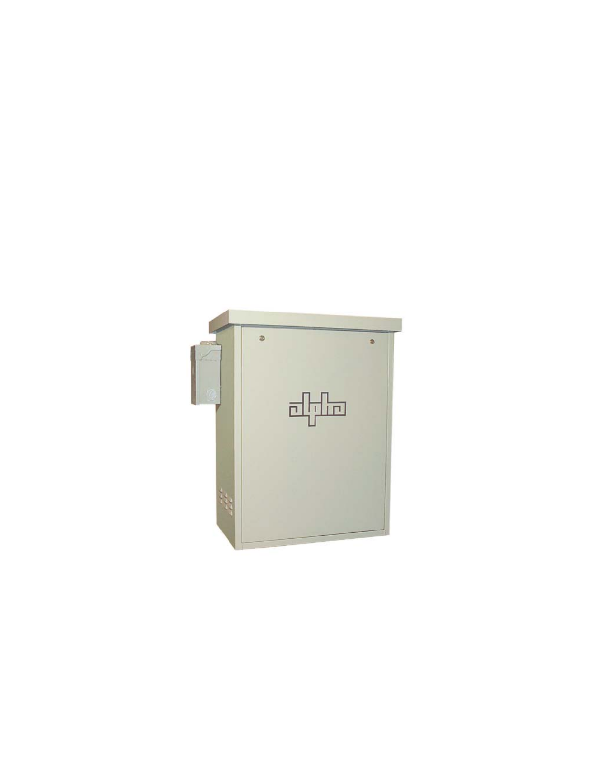
• Portable generator cabling access door
Fig. 1-1, UPE-3 Enclosure
8 031-124-C0-004, Rev. D
Page 9
1.0 Introduction, continued
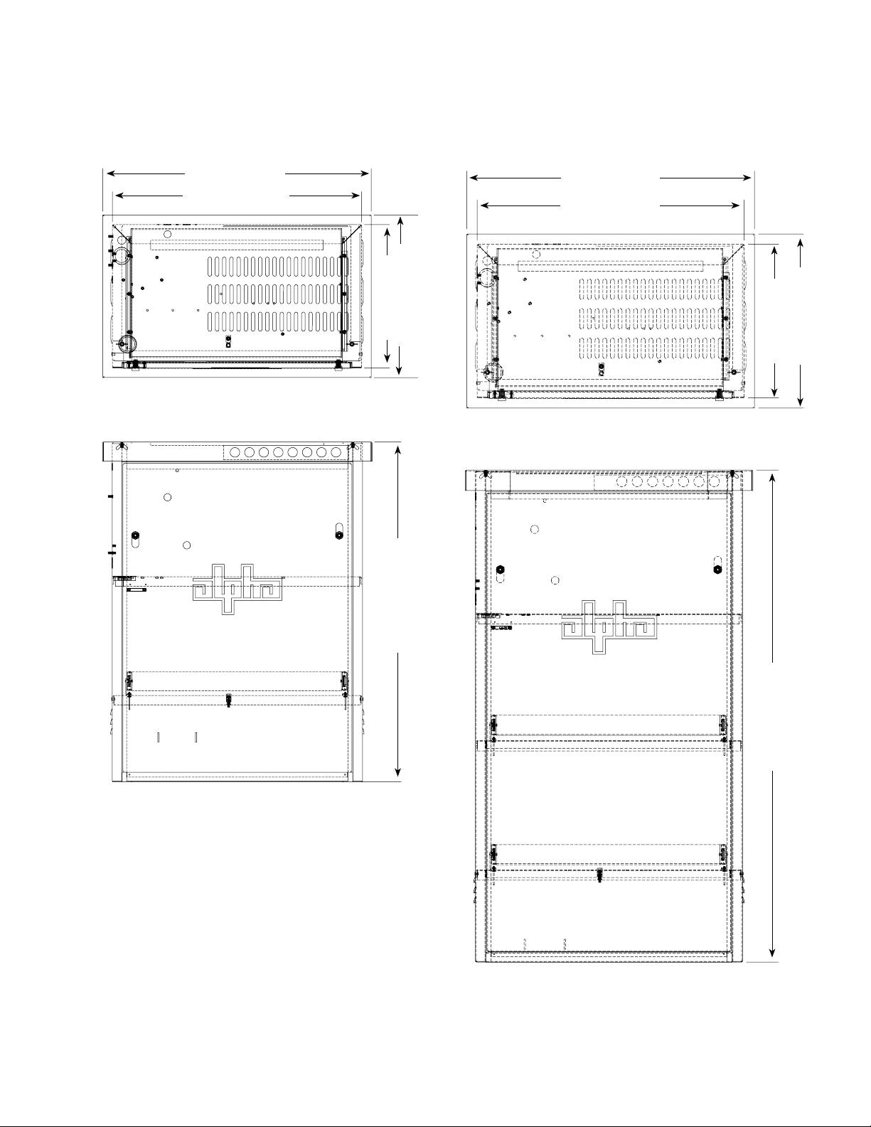
1.1 Enclosure Dimensions
28" (711.2mm)
26" (660.4mm)
17" (431.8mm)
15" (381mm)
35.4" (899.2mm)
28" (711.2mm)
26" (660.4mm)
17" (431.8mm)
15" (381mm)
UPE-3
48" (1219.2mm)
UPE-6
9031-124-C0-004, Rev. D
Page 10
1.0 Introduction, continued
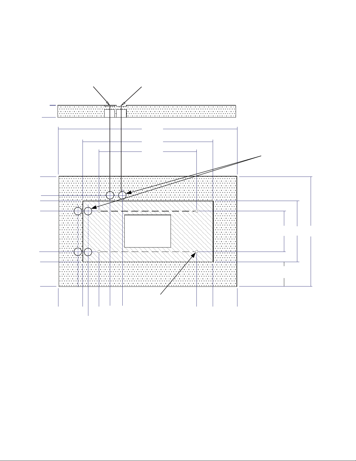
1.2 Precast Pad and Pedestal Mounting Options
Knockout for UPE 4/8
(76.2mm)
.000" (0mm)
Knockouts for
UPE 4/8
(not used)
18.5"
(469.9mm)
14.12"
(358.6mm)
12.5"
(317.5mm)
10"
(254mm)
.000" (0mm)
2.5"
(63.5mm)
(not used)
3"
Knockout for UPE 3/6
44"
(1117.6mm)
32"
(812.8mm)
24"
(609.6mm)
8" x 11.36"
(203.2mm x
288.5mm)
Cutout
Knockouts for UPE 3/6
15"
10"
(254mm)
6" (152.4mm)
(381mm)
27"
(685.8mm)
8.5"
(215.9mm)
Hole for 3/8" (9.5mm) -16
UNC insert,
shown for reference
10" (254mm)
.000" (0mm)
4" (101.6mm)
2.82" (71.6mm)
5.75" (146mm)
2.82" (71.6mm)
24" (609.6mm)
28" (711.2mm)
34" (863.6mm)
Top, Front view
Fig. 1-2, Layout for Precast Pad, Single-wide for UPE-3 and -6
Alpha P/N 641-112-10
10 031-124-C0-004, Rev. D
Page 11
1.0 Introduction, continued
1.2 Precast Pad and Pedestal Mounting Options, continued
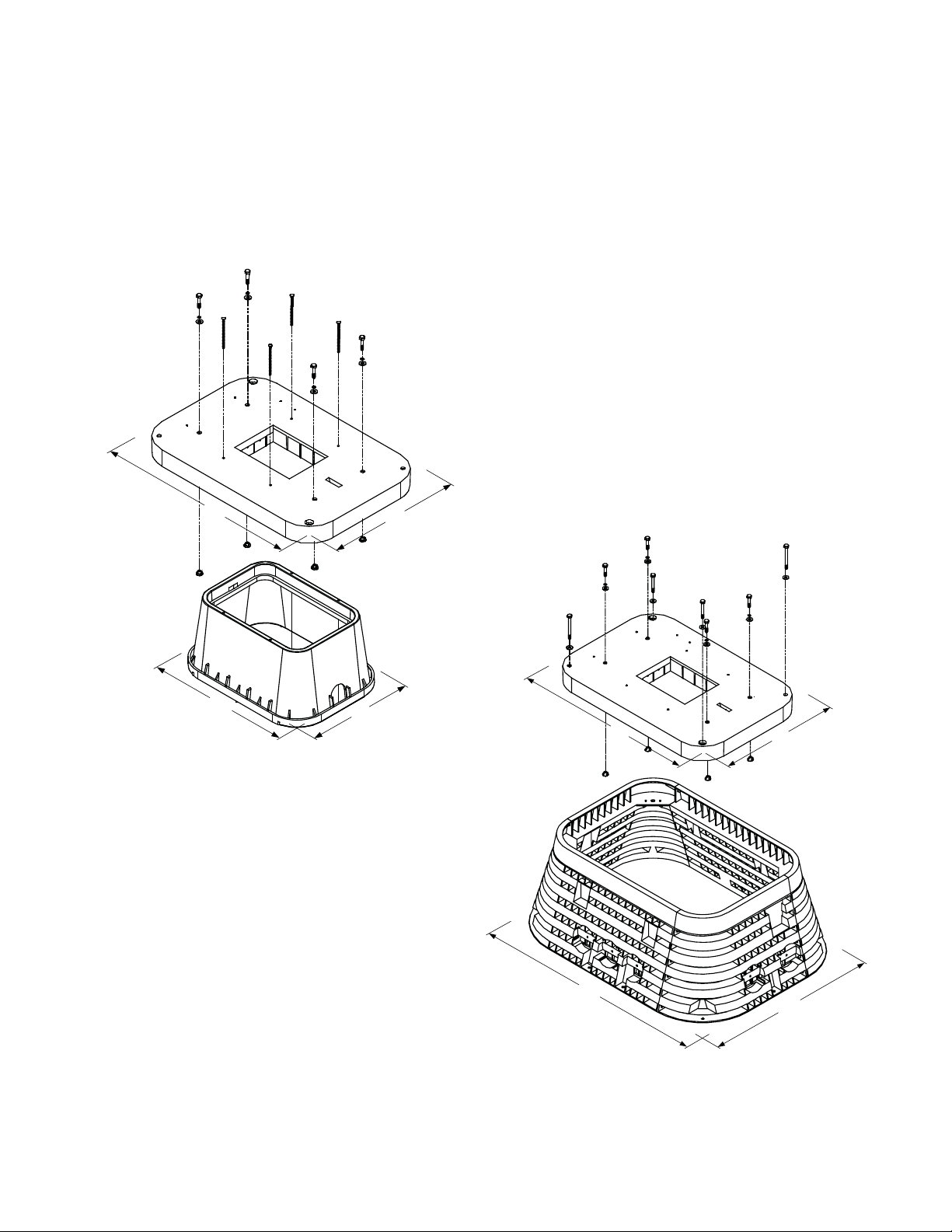
Alpha’s precast pedestal support system provides a quick, one-step solution for installing UPE Series
enclosures. Contact Alpha Technologies Customer Service (1-800-863-3930) to determine which
pedestal support is needed for your installation. Alpha recommends using the larger base, PS-6XL,
for the UPE-6.
35.75"
(908mm)
25.75"
(654mm)
19.2"
(487.7mm)
24.0"
(609.6mm)
Fig. 1-3, PS-6 Standard Pedestal (UPE-3 only)
Alpha P/N 745-324-20
35.75"
(908mm)
24.0"
(609.6mm)
43.5"
(1104.9mm)
31.75"
(806.4mm)
Fig. 1-4, PS-6XL Pedestal (UPE-3 and UPE-6)
Alpha P/N 745-324-21
11031-124-C0-004, Rev. D
Page 12

1.0 Introduction, continued
1.2 Precast Pad and Pedestal Mounting Options, continued
For detailed installation instructions, refer to the Manufacturer’s Installation Documentation included
with the pedestal support package.
Undisturbed
Ground
Backfill Pad/Pedestal
Grade
Compacted
Gravel
Fig. 1-5, Typical Site Arrangement for Pedestal and Cover
12 031-124-C0-004, Rev. D
Page 13

2.0 Installation
2.1 Site Considerations
• The site must be planned so the enclosure receives good air fl ow. If possible, in areas
of extreme heat, it is best to position the enclosure so that it will be shaded from the
afternoon sun. If no shade is available, a factory installed fan kit is highly recommended.
In areas of prevailing winds, it is best that the enclosure be located so that the sides of
the cabinet face the winds instead of the doors. This will greatly reduce the buildup of
sand or snow against the enclosure’s air vents.
• In areas of potential fl ooding, the site must be located above the 100-year fl ood plain.
• The enclosure must be placed where it will be free of obstructions, allowing easy access
to the doors for service or equipment access. For ventilation and maintenance, allow a
minimum space of 36" (914.4mm) in front, and 36" (914.4mm) in the rear between the
enclosure and other solid structures.
• Place the enclosure well away from sources of forced water, such as underground
sprinkler systems and direct roadway splash.
• The concrete pad drawing provided in this manual contains all of the required mounting
details, including electrical service and cable plant entrances.
• For ease of installation, lightweight polymer concrete pads are available from Alpha
Technologies for all UPE series enclosures.
• The vapor barrier material (such as 30 lb. felt, neoprene pond liner, or heavy grade tar
paper) must initially extend at least 6" (152.4mm) in all directions around the perimeter of
the enclosure and be trimmed closer to the enclosure.
• Contact local utilities or cable/piping locator services to ensure that the installation does
not interfere with existing cables or piping.
2.2 Transportation and Lifting
A safe means of transportation to the site and a safe procedure for unloading the enclosure
is necessary. At least two installation personnel are required to place the enclosures on the
pad. Installation team must assess the transport path for all obstructions. An obstruction free
path should be selected for transport. Use safe lifting practices. Electronic modules, batteries
or other components must not be installed until the enclosure is securely set in place at its
permanent location.
Enclosure Approximate Shipping Weight
UPE-3 61 lb. (27.7kg)
UPE-6 75 lb. (34kg)
CAUTION!
• Never transport the unit with batteries installed. Batteries must ONLY be installed after the unit
is transported to the site and secured to the pad. Transporting the unit with batteries installed
may cause a short circuit, fi re, explosion, and/or damage to the battery pack, enclosure and
installed equipment. Damage caused by improper shipping or transporting a unit with batteries
installed is not covered by the warranty.
• Enclosure must always remain in the upright position during the shipping, storage and
installation process. Damage may result from enclosure being shipped or stored on its side.
• DO NOT lift the enclosure by the cover, unless empty.
13031-124-C0-004, Rev. D
Page 14

2.0 Installation, continued
2.3 Enclosure Installation
Follow the procedure below for attaching the enclosure to a pedestal support or precast pad.
Tools and Materials Required:
• Ratchet set with 6" (152.4mm) extension.
• Vapor Barrier
• Utility Knife
CAUTION!
A 25+ year continuous vapor barrier must be used between the enclosure and pad to prevent
moisture ingress and possible corrosion caused by metal to concrete contact. The vapor barrier
material (such as 30 lb. felt, neoprene pond liner, or heavy grade tar paper) should initially extended
at least 6" (152.4mm) in all directions around the perimeter of the enclosure and later be trimmed
closer to the enclosure.
Procedure:
1. Unwrap the enclosure and inspect the contents. If items are missing or damaged, contact
Alpha Technologies and the shipper immediately.
2. Place the vapor barrier material on the pad.
3. Unbolt the enclosure from the shipping pallet.
4. With no less than two installation personnel, lift the enclosure off the shipping pallet and
place over the mounting studs on the pad.
5. Secure the enclosure to the pad using the hardware supplied with the precast pad or
pedestal support.
6. Trim the vapor barrier material.
14 031-124-C0-004, Rev. D
Page 15

2.0 Installation, continued
2.4 Attaching the External Coax Raceway
The external coax raceway is held into place by two tabs at the bottom of the raceway that fi t
into slots at the bottom of the enclosure, and a wing nut at the top.
Wing-nut
SPI
SPI
Fig. 2-1, External Coax Raceway
External Coax
Raceway
Rear Wall of UPE
Retaining Tab
15031-124-C0-004, Rev. D
Page 16

2.0 Installation, continued
2.5 Enclosure Grounding
Alpha recommends 5 ohm minimum ground resistance between enclosure and ground rods,
in accordance with IEEE 1100-1999, Powering and Grounding Electronic Equipment.
Alpha Technologies assumes no responsibility or liability for failure of the installer to comply
with the requirements of applicable local and national codes. Where allowed, exothermic
welding may be used as an alternative to Burndy clamps and connectors.
ATTENTION:
Alpha Technologies recommends using the grounding method illustrated below. The grounding method for a
particular site will be dependant upon soil type, available space, local codes, NEC (National Electric Code),
and other site-specifi c characteristics.
Connection made with Burndy
connector (P/N YG HR58 C2W-3
or equivalent)
Terminate at enclosure ground
Terminate at service
entrance ground
#6AWG
Two 8' (2.4m) ground rods, 6' (1.8m)
apart, min.
(may require additional ground rods to meet NEC
minimum grounding standard of 25 ohms or less)
Service Grounding (required)
1
2
4
Enclosure
Footprint
#2AWG
Connection made with Burndy connector
(P/N YGHP58C2W-2TN or equivalent)
2' min.
3
1
#6 bare copper wire from Service Neutral / Ground Bar with 2 ground rods located 6’ (1.8m) apart.
Lightning Protection (optional)
2
1/2" x 8' (2.4m) copper ground rod, four places, driven about 2' (0.6m) (typical) from the corners of the pad.
3
#6 bare copper wire loop terminated to each ground rod and buried below grade 30" (9.1m) (min).
Corrosion-proof connections (25+ year life-span), and hardware suitable for direct burial MUST be used.
4
#6 bare copper wire from loop to the enclosure.
16 031-124-C0-004, Rev. D
Page 17

2.0 Installation, continued
2.6 Utility Power Connection
Utility power enters the enclosure through the side or bottom of the UPE. The enclosure
accepts a standard electrical fi tting. The UPE Series can be equipped with an optional circuit
breaker assembly located in the enclosure’s module compartment.
CAUTION!
Utility Power Connection procedure must ONLY be performed by qualifi ed service personnel and
in compliance with local electrical codes and common safety practices. Connection to utility power
must be approved by the local utility before installing the power supply.
NOTE:
A “high-magnetic” or HACR (Heating, Air Conditioning, Refrigeration) circuit breaker must be
used in order to accommodate the high-inrush currents normally associated with the start-up of
ferroresonant transformers (400A, no-trip, fi rst-half cycle). Do not replace this circuit breaker with
a conventional service entrance circuit breaker. Alpha recommends Square D circuit breakers
ONLY because of increased reliability in this powering application.
Wiring From Duplex Receptacle to Service Disconnect:
In most cases, the following confi gurations qualify for service entrance use; however, other
codes may apply. Always contact your local utility to verify that the wiring conforms to
applicable codes.
240Vac Service (XM Series 2 915-240 Power Supply for UPE-3 and UPE-6):
Enclosures used with the XM Series 2 915-240 is equipped with one or two 240Vac duplex
receptacles to provide power to the power supply and peripheral equipment. The receptacle,
NEMA 6-15R, is protected by a single, 2-pole, common trip 15A circuit breaker located inside
the service entrance. Wiring is typically 14AWG per NEC code, a grounding clamp, located
on the enclosure, facilitates dedicated grounding.
120Vac 20A Service (XM Series 2 915-120 Power Supply):
Enclosures used with the XM Series 2 915-120 are equipped with one or two 120Vac duplex
receptacles to provide power to the power supply and peripheral equipment. The receptacle,
NEMA 5-20R, is protected by a single pole 20A circuit breaker located inside the service
entrance. Wiring is typically 12AWG per NEC code, a grounding clamp, located on the
enclosure, facilitates dedicated grounding.
120Vac 15A Service (XM Series 2 615):
Enclosures used with the XM Series 2 615 are equipped with one or two 120Vac duplex
receptacle to provide power to the power supply and peripheral equipment. The receptacle,
NEMA 5-15R, is protected by a single-pole, 15A High Magnetic circuit breaker located inside
the service entrance. Wiring is typically 14AWG per NEC code, a grounding clamp, located
on the enclosure, facilitates dedicated grounding.
NOTE:
Alpha recommends wiring with 12AWG to accommodate upgrade from 240Vac 15A to 120Vac 20A.
17031-124-C0-004, Rev. D
Page 18

2.0 Installation, continued
2.6 Utility Power Connection, continued
The UPE Series enclosures may be confi gured with the following service options. Please
contact your Alpha Technologies representative for assistance selecting the confi guration that
best suits your requirements.
Standard Meter Base/BBX (UMB)
EUSERC Meter Base (EMB)
(UPE-6 Only)
Internal Service Entrance (ISE)
Bottom Mount BBX/SPI (IBBX-BM)
(enclosure is upside down)
18 031-124-C0-004, Rev. D
Internal BBX (IBBX-TM)
Page 19

2.0 Installation, continued
2.6 Utility Power Connection, continued
Ground Neutral
From Utility Line 1
ON
OFF
Optional Line
Surge Arrester
To Enclosure
120Vac Service Entrance
Ground From UtilityLine 1 Line 2 Neutral
ON
OFF
Optional Line
Surge Arrester
To Enclosure
240 Vac Service Entrance
Fig. 2-2, Typical Service Entrance Wiring
19031-124-C0-004, Rev. D
Page 20

2.0 Installation, continued
2.6 Utility Power Connection, continued
Neutral
Ground
Line
Ground
Line 2
Line 1
OFF
Neutral
Ground
Line
ON
BQO, 120Vac, 20A Circuit
ON
OFF
BQO, 120Vac, 15A Circuit
Neutral
Ground
Line 2
Line 1
ON
ON
OFF
OFF
BQO, 240Vac, 15A Circuit BQO, 120/240Vac, 15A Circuit
Circuit Breaker Part Numbers
Circuit Description
240V Installation - HACR (15A) 470-224-10 Q0215
120V Installation - HM (20A) 470-017-10 Q0120HM
120V Installation - HM (15A) 470-013-10 Q0115HM
BBX - External Service Disconnect
70 Amp
BBX - External Service Dicsonnect
100 Amp
Alpha Part
Number
020-085-10 Q02-4L70RB
020-141-10 Q08-16L100RB
Square D part
Number
Fig. 2-3, Breaker-Quad-Option Wiring and Circuit Breaker Part Numbers
20 031-124-C0-004, Rev. D
Page 21

2.0 Installation, continued
2.6 Utility Power Connection, continued
Line 1 Neutral Ground
ON
OFF
Line 1 Neutral Line 2 Ground
ON
2
0
OFF
240Vac Meter Base120Vac Meter Base
Fig. 2-4, 120/240Vac UL Wiring
CAUTION!
Neutral should be bonded to ground in PRIMARY service entrance only.
21031-124-C0-004, Rev. D
Page 22

2.0 Installation, continued
2.7 Coaxial Cable Connection
1. Do NOT remove SPI cover until all sources of
power have been removed. Verify the SPI is not
connected to power supply.
2. Remove the two screws holding the cover onto the
SPI’s chassis.
3. Remove the SPI cover, exposing the circuit board
and seizure screw assembly.
WARNING!
Verify there is no power to the SPI before removing the outer cover.
Failure to do so may expose the technician to hazardous voltages.
4. Insert the coaxial termination into the output port
on the bottom of the SPI and tighten snug.
2
Seizure Screw
Seizure Screw
Assembly
3
Assembly
Circuit
Board
4
1
Output
Port
Stinger
5. Tighten the seizure screw to 35 in-lbs (4 Nm).
CAUTION!
To prevent arcing, and failure of the unit, the center conductor (stinger) of the
coaxial termination must go fully inside the seizure screw assembly.
6. Replace the SPI’s cover and reinstall the screws.
7. Verify the switch on the top of the SPI is in the ON position.
Coaxial
Termination
Seizure
Screw
5
7
6
ALT ON
6
22 031-124-C0-004, Rev. D
Page 23

2.0 Installation, continued
2.8 Power Supply Placement
Place the power supply on the top shelf over the vent louvers on the right. Do not connect
any cables or connectors to the power supply at this time.
2.9 Battery Installation
WARNING!
Battery systems represent a risk of electrical shock and high short-circuit currents. The
following precautions must be observed when maintaining batteries:
• Remove all personal metal objects (watches, rings, etc.)
• Use insulated tools
• Wear eye protection and rubber gloves
• Observe circuit polarities
• Do not make or break live circuits
• Do not lay metal tools and hardware on top of the batteries
2.9.1 Battery Date Code Usage and Identifi cation
Every battery contains a DATE CODE. This code is usually located near the positive
(+) terminal, and must be recorded in the maintenance log. If you use batteries other
than those installed by Alpha, consult the batteries’ manufacturer’s documentation for
date code type and placement.
NOTE:
The date code scheme and location varies depending on the age of the battery used.
Month: June
Fig. 2-5, Battery Date Code
Year: 2005
23031-124-C0-004, Rev. D
Page 24

2.0 Installation, continued
2.9 Battery Installation, continued
2.9.2 Battery Installation Procedure
WARNING!
To prevent arcing, never allow live battery cables to make contact with the enclosure.
Disconnect battery leads, or wrap the cable lugs with electrical tape.
CAUTION!
Threaded insert terminals require the use of 3/4" (19mm) bolts. The use of 1" (25.4mm) bolts will
seriously damage the battery. The only exception is the terminal with the large spacer for the in-line
fuse link. See Section 2.9.3 for details.
NOTE:
In battery confi gurations made up of multiple battery strings, Alpha recommends the use of in-line fuses.
Procedure:
1. Place the batteries on the enclosure’s battery slide tray or battery shelf. The correct
arrangement of the batteries on the tray or shelves varies between enclosure
models. See Figs. 2-8 and 2-9 for the correct battery arrangement. Leave a
minimum of one inch of ventilation space between the batteries.
2. To make identifi cation and record keeping easier, number and label the batteries.
Record each battery’s number and date code in the power supply maintenance log.
3. Using the battery arrangement diagrams as a reference, connect the batteries in
series to achieve 36Vdc. Refer to the diagrams for the location of the optional inline fuses. For AlphaCell batteries, torque terminal connections to approximately
65 in-lbs (7.3 Nm) at installation and re-torque to 50 in-lbs (5.6 Nm) during routine
maintenance. For non-Alpha batteries, torque to manufacturer’s specifi cations.
4. Verify the batteries are properly connected by checking the polarity and voltage
of the battery cable connector with a digital voltage meter. DO NOT connect the
battery string or strings to the power supply at this time.
5. The power supply battery charger collects battery temperature compensation
information with a Remote Temperature Sensor (RTS) attached to one of the
batteries. Refer to the Fig. 2-7 or Fig. 2-8 to determine the RTS attachment point.
See Section 3.1 for RTS the attachment procedure.
6. Route the battery cable connector into the power supply compartment. DO NOT
connect to the batteries to the power supply at this time.
CAUTION!
Recheck the polarity and voltage of the battery cable connector before proceeding. Connecting
the battery string or strings to the power supply with incorrect polarity will cause a short circuit and
possible equipment damage.
24 031-124-C0-004, Rev. D
Page 25

2.0 Installation, continued
2.9 Battery Installation, continued
2.9.3 Battery Terminal Connections
NOTE:
• Various types of batteries with different mounting styles and hardware may be shipped with the system.
ALWAYS refer to the battery manufacturer’s specifi cations for correct mounting hardware and torque
requirements. Use only the hardware and torque recommended by the battery manufacturer.
• There are two types of battery terminals: the newer, threaded insert terminals, and the older, fl ag
terminals. The following drawings and pictures are for illustrative purposes only.
Threaded Insert Terminals
CAUTION!
Threaded insert terminals require the use of 3/4" (19mm) bolts. The use of 1" (25.4mm)
bolts will seriously damage the battery. The only exception is the terminal with the large
spacer for the in-line fuse link.
3/4" (19mm) x 1/4-20 Bolt
Split Washer
Flat Washer
Battery Sense Cable
Battery Cable
Battery Terminal
Nut
Split Washer
Flat Washer
Battery Cable
In-Line Fuse Link
Flat Washer
1" (25.4mm) or 3/4" (19mm) x 1/4-20 Bolt
1" (25.4mm) x 1/4-20 Bolt
Split Washer
Flat Washer
Fuse
Spacer
Fig. 2-6 Threaded Insert Battery Terminal Connections
Battery Terminal
25031-124-C0-004, Rev. D
Page 26

2.0 Installation, continued
2.9 Battery Installation, continued
2.9.3 Battery Terminal Connections, continued
Flag Terminals
Battery Sense Cable
Flat Washer
Split Washer
Nut
Battery Cable
Battery Terminal
Nut
Split Washer
Flat Washer
Battery Cable
In-Line Fuse Link
Flat Washer
1" (25.4mm) or 3/4" (19mm) x 1/4-20 Bolt
Flat Washer
1" (25.4mm) x 1/4-20 Bolt
1" (25.4mm) x 1/4-20 Bolt
Split Washer
Flat Washer
Fuse
Spacer
Battery Terminal
Fig. 2-7, Flag Battery Terminal Connections
26 031-124-C0-004, Rev. D
Page 27

2.0 Installation, continued
2.9 Battery Installation, continued
2.9.4 Connecting the Battery Integration Tray
Connect the battery cable kit (Alpha P/N 875-690-20) to each battery, and to
matching Anderson connector on the Battery Integration Tray (BIT). Torque to the
battery manufacturer's specifi cation (for AlphaCell batteries see battery label).
Trap Door
External Generator
Connection Cabling
(Alpha P/N 875-691-20
Battery Integration
Trays
Power Supply Connection
Prewired AlphaGuard
Shelf
Prewired AlphaGuard
Shelf
Individual Battery
Connectors
(3 per tray)
2-8, Battery Integration Tray Connections
27031-124-C0-004, Rev. D
Page 28

2.0 Installation, continued
2.9 Battery Installation, continued
2.9.5 Battery Wiring Diagrams (UPE with Slide Tray)
Battery Cable Connector
(to XM2 Power Supply)
R E D (+)
B L A C K (-)
Black (-)
Red (+)
Temperature Probe
(Connected to XM2)
RTS
(Taped to side of battery)
3
Fig. 2-9, UPE-3 Battery Wiring Diagram (for use with slide tray)
2
1
In-line Fuse
(optional)
28 031-124-C0-004, Rev. D
Page 29

2.0 Installation, continued
2.9 Battery Installation, continued
2.9.5 Battery Wiring Diagrams, continued
Battery Cable Connector
(to XM2 Power Supply)
R E D (+)
B L A C K (-)
Temperature Probe
(Connected to XM2)
Red (+)
Upper Tray
Lower Tray
Black (-)
3A
3B
2A
2B
1A
RTS
(Taped to side of battery)
In-line Fuse (optional)
1B
Fig. 2-10, UPE-6 Battery Wiring Diagram (for use with slide tray)
In-line Fuse (optional)
29031-124-C0-004, Rev. D
Page 30

2.0 Installation, continued
2.10 Enclosure Protection
Alpha Technologies cannot anticipate all of the ways a vehicle may potentially threaten an
installed system, or the specifi c type of protection that is appropriate for a particular location.
The determination of the threat to the equipment and the means of protection are the
responsibility of the end user of the equipment. The following installation drawing is a general
recommendation and not intended to be a specifi c guideline for protecting the equipment. The
numbers of bollard posts (or other protection devices) depend upon equipment locations, site
surveys, traffi c patterns and local codes. Do not install enclosure within 10' (3m) of a water
sprinkler to prevent water from entering enclosure.
PAD
POSTS
Fig. 2-11, Bollard Placement
10' (3m)
min.
Sprinkler
Head
SIDEWALK
30 031-124-C0-004, Rev. D
Page 31

3.0 Enclosure Options
3.1 Battery Remote Temperature Sensor (RTS)
Procedure:
1. Attach the RTS probe to the inner side of battery 2A with adhesive tape.
2. The other side of the RTS probe is attached to the front panel of the XM2 power supply,
in the jack labeled TEMP PROBE.
CAUTION!
For enclosures with multiple battery strings, the Remote Temp Sensor (RTS) must be located with
the warmest (normally the topmost) battery string. This ensures proper operation of the battery
charger’s temperature compensation circuit. Failure to locate the RTS with the warmest battery
string could result in overcharging and premature battery failure.
Fig. 3-1, RTS Placement
31031-124-C0-004, Rev. D
Page 32

3.0 Enclosure Options, continued
3.2 Lightning and Surge Arrester Options
Alpha’s LA Series voltage suppressors provide reliable protection of power supplies and
related equipment from the damaging power line disturbances common to cable TV and
broadband applications. The LA Series incorporates Metal Oxide Varistor (MOV) technology
that effectively limits voltage surges and absorb excessive energy levels. Housed in a durable
polymer casings with standard electrical plugs, the LA Series plugs directly into any electrical
outlet.
LA - P PLUS
120VAC 20A 50/60Hz
RATED AMBIENT 55 C MAX
P/N 020-098-24
R
R
REPLACE UNIT WHEN
LAMP BECO MES DIM
OR IS OUT
LA-P Plus, 120Vac, 50/60Hz
Alpha P/N 020-098-24
The ISA-120/240 Secondary Surge Arrester (Alpha P/N 062-041-10) is hard-wired and
protects electrical equipment and wiring against lightning induced surges. The arrester diverts
lightning surges to ground, and is designed to handle repetitive operations. Severe lightning
can cause the device to fail, and it should be replaced if either of the LEDs fails to light.
LA - P PLUS
240VAC 20A 50/60Hz
RATED AMBIENT 55 C MAX
P/N 020-098-25
R
R
REPLACE UNIT WHEN
LAMP BECO MES DIM
OR IS OUT
LA-P Plus, 240Vac, 50/60Hz
Alpha P/N 020-098-25
Fig. 3-2, LA-P Plus
LA-P-120T, 120Vac, 50/60Hz
Alpha P/N 162-046-10
Fig. 3-3, ISA-120/240 Secondary Surge Arrester
32 031-124-C0-004, Rev. D
Page 33

3.0 Enclosure Options, continued
3.3 Battery Heater Mat
Battery heater mats are designed to increase battery capacity in cold environments. The
thermostat is factory set to turn the mat on at 40ºF (4.44ºC), and off as the temp rises above
50ºF (10ºC). As a safety feature, the mat has a thermal fuse that opens at 180ºF (82.22ºC) to
protect the batteries from overheating. To install the mats:
1. Remove the batteries from the tray(s).
2. Place the heater mat in the bottom of the tray(s).
3. Replace the batteries.
4. Plug the AC line cord into the closest receptacle.
3.4 LRI-ACI Lamp Option
LRI Option
The LRI lamp (red lamp) is located on the outside, on either the right or left side of the
enclosure. The lamp comes ON only when the power supply is running on backup power
(STANDBY). During normal AC line operation, the lamp remains OFF. Whenever a fault is
detected, the lamp fl ashes to indicate that service is required. The LRI can be used as a
simple form of status monitoring by allowing cable technicians to check the operational status
of the power supply without having to open the enclosure. Connect the LRI lamp to the jack
on the front of the power supply labeled LRI.
ACI Option
The AC indicator (green lamp) is located on the outside, on either the right or left of the
enclosure. When the lamp is ON, it indicates AC power is available at the power supply
output (normal operation). This allows a cable technician to drive by and determine the
status of the power supply without having to open the enclosure. Connect one connector of
the ACI lamp to the OUTPUT 1 jack on the front of the power supply, and the other to the SPI.
LRI Lamp ACI Lamp SPI
ACI Lamp
LRI Lamp
Enclosure
Wall
WHT
BLK
'Output 1'
WHT
BLK
RED
BLK
'LRI'
Fig. 3-4, ACI/LRI Wiring
33031-124-C0-004, Rev. D
Page 34

3.0 Enclosure Options, continued
3.5 Enclosure Door Tamper Switch and Cooling Fan Options
Tamper Switch
The Tamper Switch is located on the edge of the power supply shelf, opposite the power
supply. The switches are available in Normally Closed (Alpha P/N 740-216-21) and Normally
Open (Alpha P/N 740-216-26). The USM2, USM-2.5, or DSM options are required to monitor
the Tamper Switch. The connector attached to the sensor portion of the switch must be
connected to the TMPR connection on the USM or DSM card.
Tamper Switch
Magnet
Tamper Switch
Sensor
Fig. 3-5, Tamper Switch Placement
Enclosure Cooling Fan
An optional Cooling Fan Kit (Alpha P/N 745-101-22) is available for the UPE-3 and UPE-6.
The fan is thermostatically controlled, and powered by the XM Series 2 power supply.
SP
Thermosta
I
Fuse
t
Fig. 3-6, Cooling Fan Placement
34 031-124-C0-004, Rev. D
Page 35

Alpha Technologies
Power
®
Alpha Technologies
3767 Alpha Way
Bellingham, WA 98226
USA
Tel: +1 360 647 2360
Fax: +1 360 671 4936
Web: www.alpha.com
Alpha Technologies Ltd.
4084 McConnell Court
Burnaby, BC, V5A 3N7
CANADA
Tel: +1 604 430 1476
Fax: +1 604 430 8908
Alpha Technologies
Europe Ltd.
Twyford House
Thorley
Bishop's Stortford
Hertfordshire
CM22 7PA
UNITED KINGDOM
Tel: +44 0 1279 501110
Fax: +44 0 1279 659870
Alpha Technologies GmbH
Hansastrasse 8
D 91126 Schwabach
GERMANY
Tel: +49 9122 79889 0
Fax: +49 9122 79889 21
Alphatec, Ltd
P.O. Box 56468
Limassol, Cyprus
CYPRUS
Tel: +357 25 375675
Fax: +357 25 359595
AlphaTEK ooo
Khokhlovskiy Pereulok 16
Stroenie 1, Offi ce 403
109028 Moscow
RUSSIA
Tel: +7 495 916 1854
Fax: +7 495 916 1349
Alphatec Baltics
S. Konarskio G. 48
2009 Vilnius
LITHUANIA
Tel: +370 5 213 8822
Fax: +370 5 213 7799
Alpha Technologies
9, Impasse Sans Souci
92140 Clamart France
FRANCE
Tel: +33 141 900 707
Fax: +33 141 909 312
Copyright © 2008 Alpha Technologies, Inc. All rights reserved. Alpha is a registered trademark of Alpha Technologies. 031-124-C0-003, Rev. C.
Due to continuing product improvements, Alpha reserves the right to change specifi cations without notice.
 Loading...