

Page 1
Round Security Bar
Field Installation Manual
UPE-3, UPE-6, UPE-M3, UPE-M6, PN, CE and FPE Series,Enclosures
Effective: October, 2013
Page 2
Safety Notes
Review the drawings and illustrations contained in this document before proceeding. If there are any questions regarding
the safe installation or operation of the system, contact Alpha Technologies or the nearest Alpha representative. Save this
document for future reference.
To reduce the risk of injury or death and to ensure the continued safe operation of this product, the following symbols have
been placed throughout this manual. Where these symbols appear, use extra care and attention.
WARNING! ELECTRICAL HAZARD
ELECTRICAL HAZARD WARNING provides electrical safety information to PREVENT
INJURY OR DEATH to the technician or user.
WARNING! FUMES HAZARD
FUMES HAZARD WARNING provides fumes safety information to PREVENT INJURY OR
DEATH to the technician or user.
WARNING! FIRE HAZARD
FIRE HAZARD WARNING provides ammability safety information to PREVENT INJURY OR
DEATH to the technician or user.
There may be multiple warnings associated with the call out. Example:
WARNING! ELECTRICAL & FIRE HAZARD
This WARNING provides safety information for both Electrical AND Fire Hazards
CAUTION!
CAUTION provides safety information intended to PREVENT DAMAGE to material or equipment.
NOTE:
NOTE provides additional information to help complete a specic task or procedure.
ATTENTION:
ATTENTION provides specic regulatory/code requirements that may affect the placement of equipment and /or
installation procedures.
The following sections contain important safety information that must be followed during the installation and maintenance
of the equipment and batteries. Read all of the instructions before installing or operating the equipment, and save this
manual for future reference.
Page 3

Round Security Bar Field Installation Manual
UPE-3, UPE-6, UPE-M3, UPE-M6, PN, CE and FPE Series Enclosures
745-847-C1-001, Rev. B
Effective Date: October, 2013
Copyright 2013
Alpha Technologies, Inc.
member of The Group
NOTE:
Photographs contained in this manual are for illustrative purposes only. These photographs may not match
this installation.
NOTE:
Operator is cautioned to review the drawings and illustrations contained in this manual before proceeding. If
there are questions regarding the safe operation of this powering system, please contact Alpha Technologies
or the nearest Alpha representative.
NOTE:
Alpha shall not be held liable for any damage or injury involving its enclosures, power supplies, generators,
batteries, or other hardware if used or operated in any manner or subject to any condition not consistent with
its intended purpose, or is installed or operated in an unapproved manner, or improperly maintained.
TM
Contacting Alpha Technologies: www.alpha.com
For general product information and customer service (7 AM to 5 PM, Pacic Time), call
7 AM to 5 PM, Pacic Time or 24/7 emergency support
745-847-C1-001 Rev. B (10/2013)
or
1-800-863-3930
For complete technical support, call
1-800-863-3364
3
Page 4

Table of Contents
Safety Notes ....................................................................................................................................................... 5
1.0 Introduction ............................................................................................................................................... 6
1.1 Parts List ......................................................................................................................................... 6
1.2 Required Tools ................................................................................................................................ 6
2.0 Installation ................................................................................................................................................. 7
2.1 Dimensioned Enclosure Drawings .................................................................................................. 9
2.1.1 CE-3G ....................................................................................................................................... 9
2.1.2 CE-3X2 ................................................................................................................................... 10
2.1.3 CE-9G ......................................................................................................................................11
2.1.4 CE-9X2 ................................................................................................................................... 12
2.1.5 PN-3 ....................................................................................................................................... 13
2.1.6 PN-4 ....................................................................................................................................... 14
2.1.7 UPE-3 ..................................................................................................................................... 15
2.1.8 UPE-M3 .................................................................................................................................. 16
2.1.9 UPE-6 ..................................................................................................................................... 17
2.1.10 UPE-M6 .................................................................................................................................. 18
2.1.11 FPE ......................................................................................................................................... 19
Figures and Tables
Fig. 1-1 Security Lock Dimensions ............................................................................................................... 6
Fig. 2-1 Marking Guide Lines ...................................................................................................................... 7
Fig. 2-2 Drill Holes ....................................................................................................................................... 7
Fig. 2-3 Side Bracket Assembly ................................................................................................................... 8
Fig. 2-4 Lock Bracket Assembly ................................................................................................................... 8
Fig. 2-5 Installation of the Lock Shroud on the Security Bar ........................................................................ 8
Fig. 2-6 CE-3G Enclosure Hole Locations ................................................................................................... 9
Fig. 2-7 CE-3X2 Enclosure Hole Locations ............................................................................................... 10
Fig. 2-8 CE-9G Enclosure Hole Locations ..................................................................................................11
Fig. 2-9 CE-9X2 Enclosure Hole Locations ................................................................................................ 12
Fig. 2-10 PN-3 Enclosure Hole Locations .................................................................................................... 13
Fig. 2-11 PN-4 Enclosure Hole Locations .................................................................................................... 14
Fig. 2-12 UPE-3 Enclosure Hole Locations .................................................................................................. 15
Fig. 2-13 UPE-M3 Enclosure Hole Locations .............................................................................................. 16
Fig. 2-14 UPE-6 Enclosure Hole Locations ................................................................................................. 17
Fig. 2-15 UPE-M6 Enclosure Hole Locations .............................................................................................. 18
Fig. 2-16 FPE Enclosure Dimple Locations ................................................................................................. 19
Table 1-1 Enclosure Part List and Component Descriptions .......................................................................... 6
Table 1-2 Installation Tools .............................................................................................................................. 6
4
745-847-C1-001 Rev. B (10/2013)
Page 5
Round Security Bar Safety Notes
Review the drawings and illustrations contained in this manual before proceeding. If there are any questions regarding the
safe installation or operation of this product, contact Alpha Technologies or the nearest Alpha representative. Save this
document for future reference.
To reduce the risk of injury or death, and to ensure the continued safe operation of this product, the following symbols
have been placed throughout this manual. Where these symbols appear, use extra care and attention.
WARNING! ELECTRICAL HAZARD
Electrical shock can KILL. Disconnect and remove or protect all electrical equipment within
the enclosure before drilling into the enclosure.
WARNING! FIRE HAZARD
CE Model Enclosures have integrated gas lines near the enclosure door jam. Turn off the gas
before installing the enclosure and ensure all drilling locations will not damage the gas lines
before proceeding.
CAUTION!
Drilling swarf can cause laceration and puncture wounds to eyes and skin. NEVER remove drilling swarf
with bare hands. Always wear safety glasses and gloves, and use a vacuum cleaner or brush to remove
swarf from within the enclosure.
745-847-C1-001 Rev. B (10/2013)
5
Page 6
1.0 Introduction
B
A
C
Each security bar kit contains the parts and accessories needed to secure one enclosure door. If the enclosure
has both a front and back door, it will require two kits, with exception of the FPE.
1.1 Parts List
Enclosure Color Alpha Part Number
UPE
PN
CE
FPE
Seafoam Green 745-847-20
Gray 745-847-21
Seafoam Green 745-847-20
Gray 745-847-21
Seafoam Green 745-847-20
Gray 745-847-21
Seafoam Green 745-847-22
Gray 745-847-23
Pine Green 745-847-24
White 745-847-25
Table 1-1, Enclosure Part List and Component Descriptions
1.2 Required Tools
Installation tools:
Tape measure
Masking tape
1/2" drive hand drill
Center punch
7/16" socket and socket wrench
Size "K" (9/32") drill bit
4 foot level
Pencil
Utility knife
Vacuum to remove metal shavings from enclosure interior
# of Required
Kits
1
2
2
1
Kit Components Description (Qty)
• Lock Bracket (2)
• Side Bracket (4)
• Security Bar (2)
• Lock Guard (2)
• Carriage Bolt 1/4"-20X3/4" (12)
• Lock Washer 1/4" (12)
• Flat Washer 1/4" (12)
• Hex Nut 1/4"-20 (12)
• Lock Bracket (4)
• Side Bracket (8)
• Security Bar (4)
• Lock Guard (4)
• Carriage Bolt 1/4"-20X3/4" (24)
• Lock Washer 1/4" (24)
• Flat Washer 1/4" (24)
• Hex Nut 1/4"-20 (24)
Table 1-2, Installation Tools
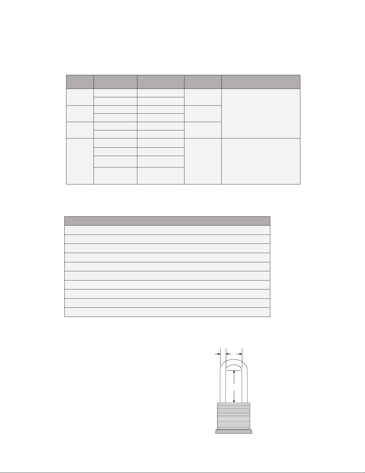
In addition:
To secure the enclosure, each bar requires a
security lock. Each user-supplied lock must meet
the following dimensions:
Where:
A = 5/16"
B = 3/4"
C = 2 1/2"
Fig. 1-1, Security Lock Dimensions
6
745-847-C1-001 Rev. B (10/2013)
Page 7

2.0 Installation
This procedure applies to each of the supported enclosures. Refer to Section 2.1 Dimensioned Enclosure
Drawings for specic information pertaining to the enclosure onto which the kit(s) will be installed.
All enclosures require installation of both side brackets and lock brackets. The side brackets hold the security bar,
and the lock brackets hold the security lock (refer to Figures 2-3 and Figure 2-4).
WARNING! FIRE HAZARD
A gas line runs behind the door jamb on the 5K generator enclosure (CE Series). Turn off the gas prior
to installing the security bar. Be careful not to puncture or damage the line. Upon completion of the
installation procedure, turn gas on and perform a leak test before leaving the site.
1. Use a 4-ft level to mark the front of the enclosure at the
height indicated for the enclosure (see Fig. 2-1).
2. Measure from the sides and mark the holes with a center
punch. These will be the top holes used by the side
brackets.
3. Remove the door.
4. Place cardboard or a similar material behind the door jamb
to protect the electronic equipment from the metal shavings
created while drilling. Use a vacuum cleaner to remove the
shavings when drilling is complete.
5. Drill the holes using a 9/32" drill bit.
Fig. 2-1, Marking Guide Lines
Drill Holes
See Diagrams
for Specic
Dimensions
Fig. 2-2, Drill Holes
6. Line up the top hole of the side bracket with the hole drilled in the enclosure in step 5. The side bracket
provides a template to accurately mark the bracket’s bottom hole locations.
7. Mark the bottom holes with the center punch.
8. Drill the bottom holes of the side brackets using a 9/32" drill bit.
9. On the door removed in step 3, measure and mark the top hole locations for the lock brackets and drill using
a 9/32" drill bit.
10. Line up the top hole of the lock bracket with the hole drilled in the door in step 9. The lock bracket acts as a
template.
11. Mark the locations of the bottom holes with the center punch and using a 9/32" drill bit, drill the bottom holes.
Guide Line
Drill
Holes
NOTE:
Where necessary, use the utility knife to trim and remove insulation from inside the door.
745-847-C1-001 Rev. B (10/2013)
7
Page 8

2.0 Installation
12. Use the hardware provided to mount the side brackets and lock brackets to the enclosure and to the door.
Fig. 2-3, Side Bracket Assembly
(enclosure door/sides removed for clarity)
NUT 1/4"-20 (2 PLACES)
LOCK WASHER 1/4" (2 PLACES)
FLAT WASHER 1/4" (2 PLACES)
ENCLOSURE DOOR
LOCK BRACKET
CARRIAGE BOLT
1/4"-20 X 3/4"
Fig. 2-4, Lock Bracket Assembly
13. To secure, slide lock guard over bracket, insert lock into guard, slide bar through the opening and close lock.
LOCK GUARD
LOCK BAR
LOCK
Fig. 2-5, Installation of the Lock Shroud on the Security Bar
8
745-847-C1-001 Rev. B (10/2013)
Page 9

2.0 Installation
2.1 Dimensioned Enclosure Drawings
The dimensioned enclosure drawings in this section provide specic hole placement locations for the
Security Bar bracket mounting hardware.
2.1.1 CE-3G
WARNING! FIRE HAZARD
CE Model Enclosures have integrated gas lines near the enclosure door jam. Turn off the gas
before installing the enclosure and ensure all drilling locations will not damage the gas lines
before proceeding.
2 1/8"
25 7/8"
Side Brackets
Location of bracket mounting holes
Lock Bracket
2 9/16"
25 7/16"
2 1/8"
9 1/16"
11/16"
11/16"
745-847-C1-001 Rev. B (10/2013)
1 1/16"
11/16"
11/16"
11 7/16"
Fig. 2-6, CE-3G Enclosure Hole Locations
All dimensions in inches.
2 9/16"
5 11/16"
11/16"
9
Page 10

2.0 Installation
FRONT VIEW
BACK VIEW
2.1 Dimensioned Enclosure Drawings, continued
2.1.2 CE-3X2
WARNING! FIRE HAZARD
CE Model Enclosures have integrated gas lines near the enclosure door jam. Turn off the gas
before installing the enclosure and ensure all drilling locations will not damage the gas lines
before proceeding.
Alternate Mounting position
when used with shrouded door
CE-3X2 with Security Option
2 1/8"
25 7/8"
2 1/8"
9 1/16"
Location of bracket mounting holes
ALTERNATE MOUNTING POSITION
2 9/16"
25 7/16"
2 9/16"
5 11/16"
10
11/16"
11 7/16"
4 9/16"
11/16"
11 7/16"
11/16"
Fig. 2-7, CE-3X2 Enclosure Hole Locations
All dimensions in inches.
1 1/16"
11/16"
745-847-C1-001 Rev. B (10/2013)
Page 11

2.0 Installation
FRONT VIEW BACK VIEW
2.1 Dimensioned Enclosure Drawings, continued
2.1.3 CE-9G
WARNING! FIRE HAZARD
CE Model Enclosures have integrated gas lines near the enclosure door jam. Turn off the gas
before installing the enclosure and ensure all drilling locations will not damage the gas lines
before proceeding.
2 1/8"
33 7/8"
2 1/8"
9 1/16"
Location of bracket mounting holes
2 9/16"
33 7/16"
2 9/16"
5 11/16"
11 7/16"
11/16"
1 1/16"
11/16"
Fig. 2-8, CE-9G Enclosure Hole Locations
All dimensions in inches.
745-847-C1-001 Rev. B (10/2013)
11/16"
11 7/16"
11/16"
11
Page 12

2.0 Installation
2.1 Dimensioned Enclosure Drawings, continued
2.1.4 CE-9X2
WARNING! FIRE HAZARD
CE Model Enclosures have integrated gas lines near the enclosure door jam. Turn off the gas
before installing the enclosure and ensure all drilling locations will not damage the gas lines
before proceeding.
2 1/8"
32 7/8"
2 1/8"
9 1/16"
Location of bracket mounting holes
2 9/16"
32 7/16"
2 9/16"
5 11/16"
12
11/16"
11 7/16"
FRONT VIEW
Fig. 2-9, CE-9X2 Enclosure Hole Locations
11/16"
11/16"
All dimensions in inches.
11 15/32"
BACK VIEW
745-847-C1-001 Rev. B (10/2013)
11/16"
1 1/32"
Page 13

2.0 Installation
FRONT VIEW BACK VIEW
2.1 Dimensioned Enclosure Drawings, continued
2.1.5 PN-3
2 1/8"
25 7/8"
2 1/8"
9 1/16"
Location of bracket mounting holes
2 9/16"
25 7/16"
2 9/16"
5 11/16"
11/16"
11 7/16"
745-847-C1-001 Rev. B (10/2013)
1 1/16"
11/16"
11/16"
11 7/16"
Fig. 2-10, PN-3 Enclosure Hole Locations
All dimensions in inches.
11/16"
13
Page 14

2.0 Installation
2.1 Dimensioned Enclosure Drawings, continued
2.1.6 PN-4
Location of bracket mounting holes
2 1/8"
32 7/8"
2 1/8"
9 1/16"
11/16"
11 7/16"
1 1/16"
11/16"
11/16"
11 7/16"
2 1/8"
32 7/16"
2 9/16"
5 11/16"
11/16"
14
FRONT VIEW BACK VIEW
Fig. 2-11, PN-4 Enclosure Hole Locations
All dimensions in inches.
745-847-C1-001 Rev. B (10/2013)
Page 15

2.0 Installation
FRONT VIEW
2.1 Dimensioned Enclosure Drawings, continued
2.1.7 UPE-3
Location of bracket mounting holes
2 1/8"
16 7/8"
2 1/8"
10 1/16"
7/16"
11 7/8"
2 9/16"
16 7/16"
2 9/16"
7 11/16"
7/16"
745-847-C1-001 Rev. B (10/2013)
Fig. 2-12, UPE-3 Enclosure Hole Locations
All dimensions in inches.
15
Page 16

2.0 Installation
FRONT VIEW
2 9/16
"
15 3/16
"
2 9/16
"
6 11/16
"
7/16
"
7/16
"
11 15/16
"
9 1/16
"
2 1/8
"
15 5/8
"
2 1/8
"
2.1 Dimensioned Enclosure Drawings, continued
2.1.8 UPE-M3
Location of bracket mounting holes
Fig. 2-13, UPE-M3 Enclosure Hole Locations
All dimensions in inches.
745-847-C1-001 Rev. B (10/2013)
16
Page 17

2.0 Installation
FRONT VIEW
2.1 Dimensioned Enclosure Drawings, continued
2.1.9 UPE-6
Location of bracket mounting holes
2 1/8"
26 7/8"
2 1/8"
10 1/16"
2 9/16"
26 7/16"
2 9/16"
7 5/8"
7/16"
745-847-C1-001 Rev. B (10/2013)
11 7/8"
7/16"
Fig. 2-14, UPE-6 Enclosure Hole Locations
All dimensions in inches.
17
Page 18

FRONT VIEW
2 1/8"
28 1/8"
2 1/8"
9 1/16"
7/8"
7/8"
11 15/16"
6 11/16"
2 9/16"
2 9/16"
27 11/16"
2.0 Installation
2.1 Dimensioned Enclosure Drawings, continued
2.1.10 UPE-M6
18
Fig. 2-15, UPE-M6 Enclosure Hole Locations
All dimensions in inches.
745-847-C1-001 Rev. B (10/2013)
Page 19

2.0 Installation
FRONT VIEW
18"
2 1/8"
25"
2 1/8"
10 1/16"
3/4"
17 1/4"
7 5/8"
7 1/2"
2 9/16"
26 7/16"
2 9/16"
3/4"
28 3/8"
2.1 Dimensioned Enclosure Drawings, continued
2.1.11 FPE
Location of bracket mounting dimples/drill locations
Fig. 2-16, FPE Enclosure Dimple Locations
All dimensions in inches; dimensions are for reference purposes.
745-847-C1-001 Rev. B (10/2013)
19
Page 20

Alpha Technologies Inc.
3767 Alpha Way
Bellingham, WA 98226
United States
Tel: +1 360 647 2360
Fax: +1 360 671 4936
Alpha Technologies Ltd.
7700 Riverfront Gate
Burnaby, BC V5J 5M4
Canada
Tel: +1 604 436 5900
Fax: +1 604 436 1233
Toll Free: +1 800 667 8743
Alpha Industrial Power Inc.
1075 Satellite Blvd NW,
Suite 400
Suwanee, GA 30024
United States
Tel: +1 678 475 3995
Fax: +1 678 584 9259
Alpha Energy
1628 W Williams Drive
Phoenix, AZ 85027
United States
Tel: +1 602 997 1007
Fax: +1 623 249 7833
Alpha Technologies Europe Ltd.
Twyford House Thorley
Bishop’s Stortford
Hertfordshire, CM22 7PA
United Kingdom
Tel: +44 1279 501110
Fax: +44 1279 659870
Alpha Technologies
Suite 1903, Tower 1
33 Canton Road
Hong Kong, China
Phone: +852 2736 8663
Fax: +852 2199 7988
Alpha Technologies GmbH
Hansastrasse 8
D-91126
Schwabach, Germany
Tel: +49 9122 79889 0
Fax: +49 9122 79889 21
Alphatec Ltd.
339 St. Andrews St.
Suite 101 Andrea Chambers
P.O. Box 56468
3307 Limassol, Cyprus
Tel: +357 25 375 675
Fax: +357 25 359 595
Alpha Innovations Brasil
Avenida Ibirapuera,
2120 – Cj 76
Moema - 04028-001
Santos SP, Brazil
Tel: +55 11 2476 0150
Fax: +55 11 2476 0150
Technologies Argus
First de Mexico
Anatole France Num. 17
Colonia Polanco
11560, México D.F.
Tel: +52 55 5280 6990
Alpha TEK ooo
Khokhlovskiy Pereulok 16
Stroenie 1, Ofce 403
Moscow, 109028
Russia
Tel: +7 495 916 1854
Fax: +7 495 916 1349
Alphatec Baltic
S. Konarskio Street 49-201
Vilnius, LT-03123
Lithuania
Tel: +370 5 210 5291
Fax: +370 5 210 5292
Visit us at www.alpha.com
Due to continuing product development, Alpha Technologies reserves the right to change specications without notice.
Copyright © 2013 Alpha Technologies. All Rights Reserved. Alpha® is a registered trademark of Alpha Technologies.
745-847-C1-001 Rev. B (10/2013)
 Loading...