

Power
Security Bar Field Installation InstructionsFiel
For UPE-3, UPE-6, UPE-M3, UPE-M6, PN Series and CE Series Enclosures
Each security bar kit contains the parts and accessories needed to secure one enclosure door. Enclosures with both a front and back
door, require two kits. Detailed placement specifi cations for each supported enclosure are in the Security Bar Field Installation Manual
(Search for P/N 745-847-C1-001) available at www.alpha.com.
®
Tools and Materials Required
• Hand drill
Center punch
•
Pop rivet tool with 5/32" nose piece
•
4-foot level
•
• #20 drill bit
• Tape measure
Masking tape
•
Pencil
•
Utility knife
•
Vacuum to remove metal shavings from cabinet interior
•
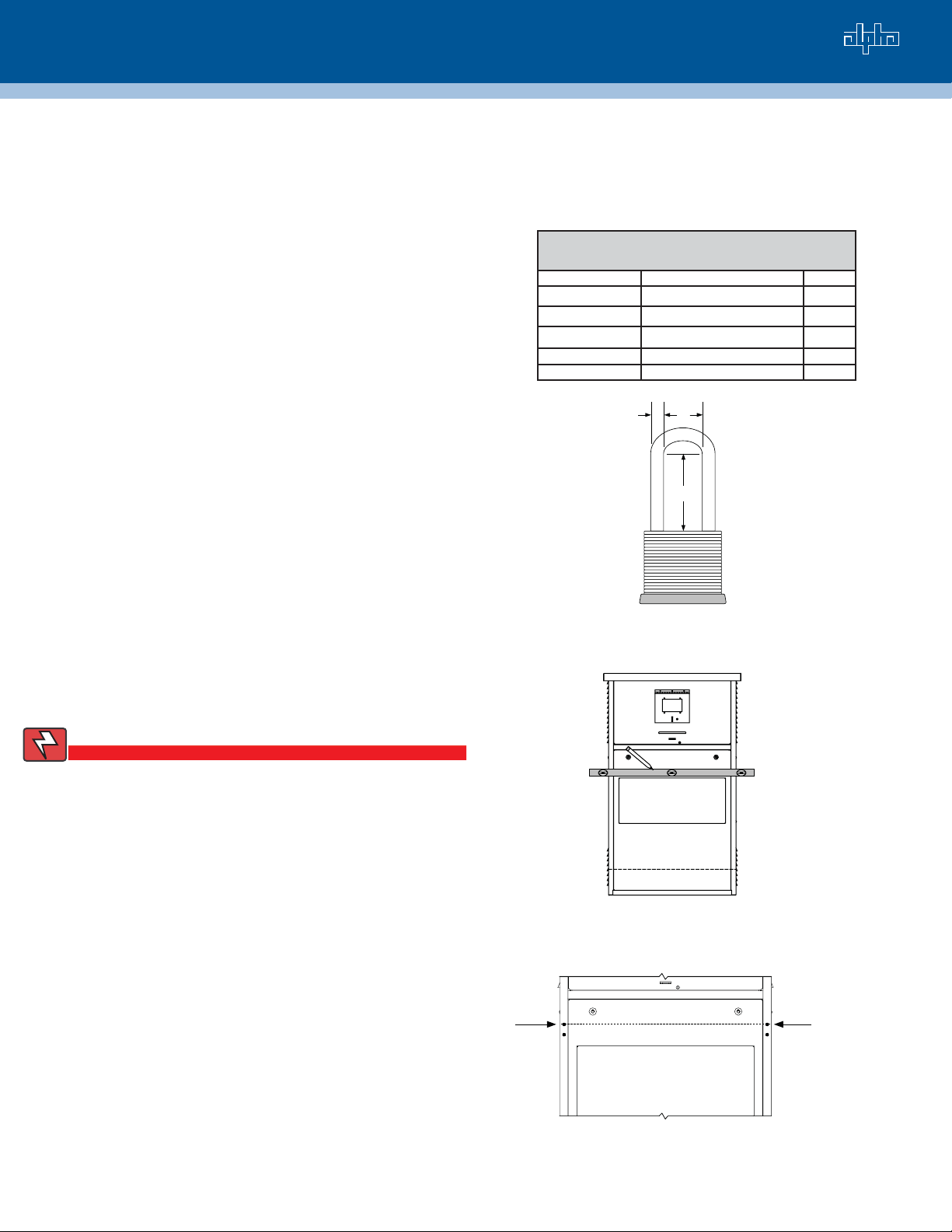
Lock, see Fig. 1 for dimensions
•
Installation
The installation outlined below applies to each of the
supported enclosures. On all enclosures you must install
side brackets and lock brackets. The side brackets hold the
security bar, and the lock brackets hold the security lock.
See Figs. 4 and 5.
If needed, detailed placement specifi cations for each
supported enclosure are in the Security Bar Field
Installation Manual (Alpha P/N 745-847-C1-001) available
at www.alpha.com.
Material List, Security Bar Kit
UPE-3, UPE-6, UPE-M3, UPE-M6, PN and CE Series
Alpha P/N Description Qty
605-348-J2-002 Side Bracket 4
605-346-J2-003 Lock Bracket 2
605-345-R2-001 Security Bar 2
636-005-12 Rivets 12
633-294-12 Washers 12
A
B
C
Where:
A= 5/16"
B= 3/4"
C= 2 1/2"
Fig. 1
WARNING!
A gas line runs behind the door jam on the 5K generator.
Turn off the gas prior to installing the security bar. Be
careful not to puncture or damage the line.
Using a 4-ft level and a pencil, mark the front of
1.
the enclosure where you want to place the top side
brackets and bar. See recommended placement
specifi cations available at www.alpha.com (P/N 745-
847-C1-001). See Fig. 2.
Measure from the sides and mark the holes with a
2.
center punch. These will be the top holes used by
the side brackets.
Remove the door.
3.
Place cardboard behind the door jam to protect
4.
the electronic equipment from the metal shavings
created during drilling. The carboard defl ects
the shavings, and should be removed when the
installation is complete.
Drill the holes using a #20 drill bit. See Fig 3.
5.
Fig. 2
GuideLine
Fig. 3
Mark guide lines
to aid in placing
the top side
brackets and
security bar.
Drill holes
Page 1 of 2
Total Power Solutions
m
Argus Cordex™ CXRC 2RU SeriesArgus Cordex™ CXRC 4RU Series
Installing the Security Bar, continued
6.
Line up the top hole of the side bracket with the hole drilled
in the enclosure in Step 5. The side bracket provides
a template for you to mark the bracket’s bottom hole
locations.
7.
Mark the bottom holes with the center punch.
8.
Drill the bottom holes of the side bracket using a #20 drill
bit. Repeat for the other side.
9.
On the removed door (Step 3), measure and mark the top
hole locations for the lock brackets. While you can use
the side brackets and security bar to determine the drill
location, the lock brackets are not horizontally aligned with
the side brackets, but are offset.
10.
Use a #20 drill bit to drill the holes.
11.
Align the top hole of the lock bracket with the hole drilled
in the door in Step 10. Using a center punch and the lock
bracket as a template, mark the locations of the bottom
hole.
12.
Using a #20 drill bit, drill the bottom holes.
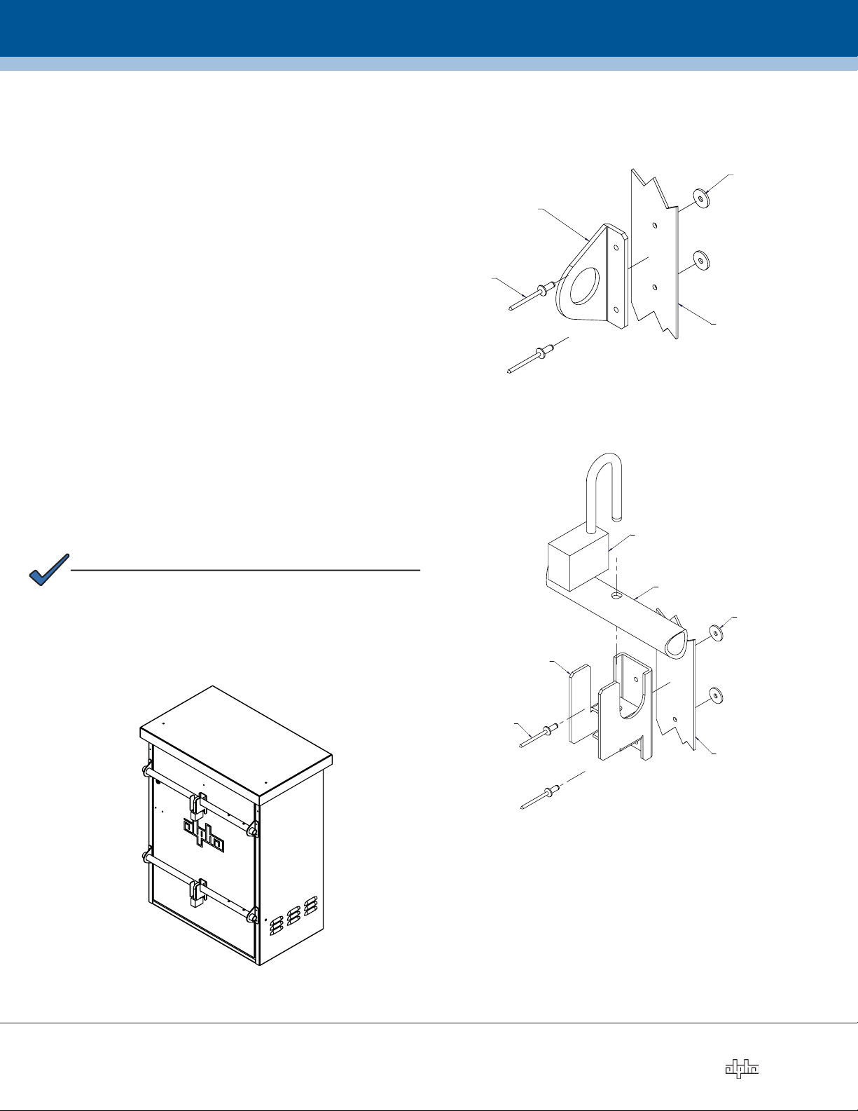
13.
Rivet the side brackets and lock brackets to the enclosure
and to the door. See Figs. 4 and 5.
14.
Install the second bar, repeating the necessary steps.
15.
Remove metal shavings.
16.
Replace the door on the enclosure and insert and
lock
security bar into the brackets.
FLAT WASHER (2 PLACES)
SIDE BRACKET
RIVET (2 PLACES)
ENCLOSURE
Fig. 4, Side Bracket Assembly
LOCK
NOTE:
Where necessary, use the utility knife to cut and remove
insulation from the rivet area.
DETAILED SPECIFICATIONS FOR EACH SUPPORTED
ENCLOSURE ARE IN THE SECURITY BAR FIELD
INSTALLATION MANUAL (SEARCH FOR P/N 745-847-C1-001)
A VAILABLE AT WWW.ALPHA.COM.
LOCK BAR
FLAT WASHER (2 PLACES)
LOCK BRACKET
RIVET (2 PLACES)
ENCLOSURE DOOR
Fig. 5, Lock Bracket Assembly
Fig. 6, UPE3 Enclosure with Security Bars
For more information visit www.alpha.com
United States Bellingham, Washington Tel: 360 647 2360 Fax: 360 671 4936
Canada Burnaby, British Columbia Tel: 604 430 1476 Fax: 604 430 8908
Alpha Technologies reserves the right to make changes to the products and information contained in this document without notice.
Copyright © 2006 Alpha Technologies. All Rights Reserved. Alpha® is a registered trademark of Alpha Technologies. member of The Alpha Group™ is a trademark of Alpha Technologies.
745-847-C2-001, Rev. A (08/2006)
ember of The Group
Page 2 of 2
TM
 Loading...