

Page 1
INDUSTRIAL
POWER
Set-Up Instructions
(Liner-Based System)
UL LISTED
________________Important_________________
Read set-up instructions before assembly.
Report any shortages within 72 hours
Specializing in Environmental and Fire-Life
Safety Compliance for Stationary Battery
Systems
11/07 Rev B
Page 2

Table of Contents
Part Familiarization…………………………………………………. 2
Required Tools………..……….................................................... 3
Step 1 Verify Measurements…………………………………….... 4
Step 2 Floor Preparation …………............................................. 4
Step 3 Liner Layout………………………………………………… 5
Step 4 Rack & Battery Installation……………………………….. 6
Step 5 Seal Rack & Anchor Bolts………………………………... 7
Step 6 Containment Layout ……………………………….……… 7
Step 7a Barrier Installation w/Anchor Bolts …………………... 8
Step 7b Barrier Installation with Adhesive Option …………… 8
Step 8 Final Assembly – Extrusion Clips ……………………… 9
Step 9 Pillow Installation………………………………………….. 9
Installation Training………………………………………………… 12
Maintenance………………………………………………………….. 13
Page 3
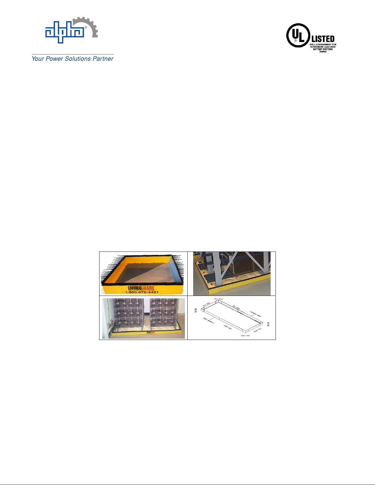
Product Familiarization
Page 2
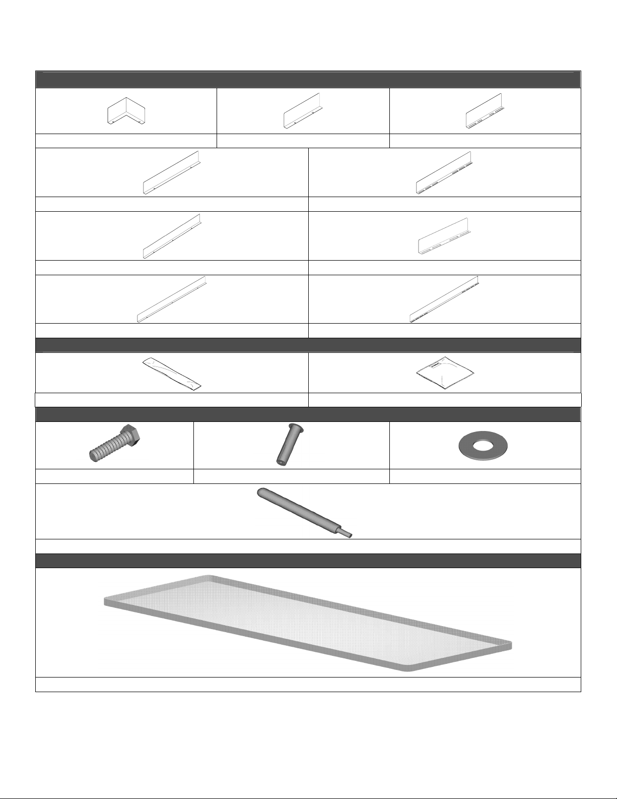
Component Listing:
EAGLE BARRIER WALLS
001-06 002-12 002-12ADJ
002-24 002-24ADJ
002-36 002-14ADJ
002-48 002-48ADJ
PILLOWS
SOC NABPILL
FLOOR ANCHORING HARDWARE
1/4” Floor Anchor Bolt Drop-In Floor Anchor Floor Anchor Washer
Anchor Setting Tool
UL LISTED FACTORY FORMED LINER
Corrosion Resistant Liner
Page - 2 -
Page 4

Page 3
Tools Required for Installation
Anchor Setting tool (Provided)
Caulking Gun (Provided)
Hammer Drill
Hammer
Ratchet w/ 7/16” and ½” Sockets
Chalk Line
Duct Tape
Non-Conductive Measuring Tape
Marker
Utility Knife with Regular or Hook Blades
Side Cutters (Snips)
Throw-away Latex Gloves
Dust Pan and Hand Broom
Vacuum
Safety Glasses
Page 5

Level 1 “New Installations”
Page 4
A “new installation” is defined by EnviroGuard as a spill containment installation
where the battery rack has not yet been installed.
NOTES:
1. Installations Utilizing Pre-Fabricated Corrosion Resistant Liner
2. This Procedure is for New Installations ONLY.
3. The gray
Step 1
Verify Measurements
Prior to starting the job, review the CAD drawing and compare it with the
actual kit. Verify measurements of the battery rack being used. If a
problem exists, contact the necessary management. (This procedure
should take place in the job walk; problems should have been identified
then, check the job walk checklist)
Step 2
Floor Preparation
Clean floor thoroughly of any debris that may interfere with a tight seal
between the floor and the spill containment barrier. Snap a chalk line
according to spill containment outside dimensions to identify exact
location. (Figure 1)
Note: Spill containment barrier walls must be at least 1” away from rack,
VRLA stack or cabinet outside dimensions in all directions when job is
complete.
side of the liner must face up.
Figure 1
Page 6

Step 3
Page 5
Liner Layout
Layout the liner, with gray side up, within the chalk line area and measure
liner to confirm inside dimensions (Figure 2a). Using duct tape, secure the
liner to the floor and remove wrinkles and folds (Figure 2b).
Apply Duct Tape Here
Figure 2a
Figure 2b
Page 7

Step 4
Page 6
Rack & Battery Installation
Always check for rebar or underground obstructions before drilling!
Assemble rack according to rack manufacture instructions. Center the
rack on the inside of the liner. Be very careful not to tear the liner by
shifting the rack. (Figure 3) Check to ensure distances from wall comply
with local codes. The liner should extend beyond the rack evenly on all
sides. (Figure 4) Verify aisle width and distance needed from wall. Mark
the locations of the holes to be drilled for the rack. Drill holes for rack
anchor bolts. Clean holes and remove debris.
Figure 3
Centering the rack on the liner is very critical. If another installer is
responsible for placing the rack, make sure it’s centered prior to drilling.
Figure 4
Page 8

Page 7
Step 5
Sealing Rack Anchor Bolts
Coat each rack anchor bolt with Acid Resistant sealant before placement.
Insert anchor bolt through washer (Figure 5a). Run a bead of AcidResistant sealant around rack footprint and anchor bolts. Lay 1/8”
Masonite sheet over the liner to protect liner from equipment and lifts. Set
the batteries in the rack (Figure 5b). Remove Masonite and duct tape.
Figure 5a Figure 5b
Step 6
Containment Layout
Lay out all “Eagle Barrier Walls” on the floor around the liner according to
the CAD assembly drawing (Figure 6). Assemble the wall components by
matching the labeled part numbers shown on the CAD drawing. For the
required configuration, use the slots on the adjustable components for
proper sizing. Use the Extrusion Clips to keep Barrier Walls in place
during installation. Barrier Walls should be at least 1” away from rack in
all directions. Using Barrier Wall components as a template mark the
location of the holes to be drilled in the floor. Remove the Extrusion from
the Barrier Walls. Remove the Barrier Walls carefully and note the
orientation of the components.
Figure 6
Page 9

Page 8
Step 7a
Drilling Holes & Installing Floor Anchors
Always check for rebar or underground obstructions before drilling!
Using the drill bit provided, drill holes to 1” depth at previously marked
locations (Figure 7). Clean drill holes as you go using shop vacuum with
Hepa Filter. Insert drop-in floor anchors and insure top of anchor is flush
with floor.
Drill to 1” depth
Figure 7 Figure 8
Place Barrier Walls back over the perimeter to check alignment and hole
accuracy. Using the anchor punch tool set the drop-in floor anchors into
the floor. After all components have been situated, continue to secure the
remaining Barrier Walls to the floor by tightening the floor anchor
assembly bolts, using a 7/16” socket, 110 inch pounds.
ÆRack
Page 10

Step 8
Page 9
Final Assembly
Place the Extrusion Clips over the top of the Barrier Wall securing the liner
to the wall. In the event that height of the liner exceeds the Barrier Walls,
trim the liner as necessary after liner has been pushed fully into
containment. Continue installing the extrusion clips over Barrier Walls and
liner (Figure 10).
CAUTION:
Figure 10
Step 9
DO NOT USE BARRIER WALL AS A GUIDE TO TRIMMING!
Figure 9
Installing Neutralizing Pillows
Install pillows inside the floor of the liner. Spread pillows out to cover the
maximum amount of space. Place serial numbers facing up and in the
same direction whenever possible. Please note that the rack stanchions
may interfere with uniform pillow layout (Figure 11).
Figure 11
Page 11

Inspection & Maintenance
Page 10
Scheduled Maintenance
Once a year, EnviroGuard recommends inspection of all acid resistant
approved sealant. EnviroGuard also recommends that a new bead of
sealant be applied to the locations as specified in the setup instructions,
as required. Acid Resistant sealant should be checked for cracks or
leaks, due to concrete settlement and cracking expected with aging.
Check that all bolts are tightened to 110 inch pounds and recoated rack
mounting bolts as needed with sealant. A visual inspection of the
neutralizing & absorption pillows should take place. If the pillows or
SOCs have turned color, they may be contaminated. Any
contaminated pillows or SOCs should be replaced immediately.
Sealant Removal
In the event that removal of sealant is necessary, mineral spirits may be
used to ease removal, however the best method is to use a putty knife and
be very careful not to damage the liner. Exercise extreme caution when
using chemicals such as mineral spirits, as they can cause severe
damage to batteries and equipment.
Pillow Inspection & Evaluation for Replacement
Neutralizing & Absorption Pillows are designed to react with sulfuric
acid/electrolyte. Water and/or excessive humidity will, on occasion, cause
discoloration. Contact with water over time may cause pillows to need
replacing prematurely. It is recommended that absorption pillows and
SOCs are replaced when replacing batteries. Ask about EnviroGuard’s
pillow credit recycling & disposal services nationwide at (800) 206-9884.
Disassembly of Side Barriers Walls for Battery Service
NOTE: The following procedure should be used for the removal or
replacement of batteries. Always use protective equipment when
servicing battery strings.
Determine which Barrier Walls need to be removed for battery service.
Extract the floor anchor assembly bolts from the components to be
dislodged. Remove the Barrier Walls.
Lay a 1/8” Masonite sheet over the liner to protect liner from equipment
and lifts. Remove batteries to be replaced or serviced. Set the batteries
in the rack. Return the Barrier Walls to their previous location and replace
floor anchor bolts. Tighten to 110 inch pounds.
 Loading...