

Page 1
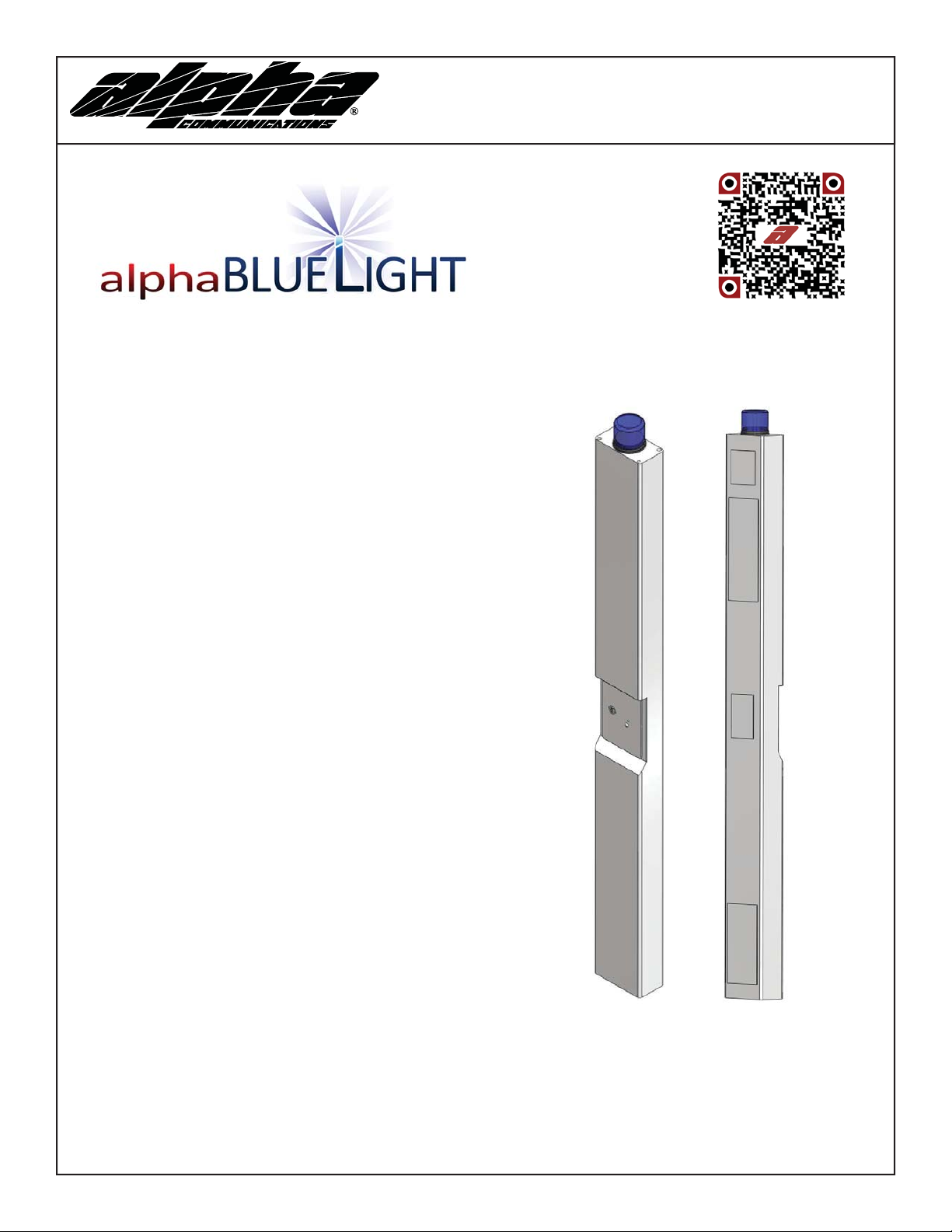
AlphaBlueLight™ Emergency Towers
FEATURES
• ADA Compliant (hands free operation)
• LED call status indicator
• Powder coated steel construction inside and
out
• Aluminum access panels powder coated
inside and out
• Weather and vandal resistant
• Blue beacon and strobe with photocell
• Strobe turns on upon phone activation
• Recessed illuminated faceplate
• Internal anchor base plate
• Ability to program up to 5 emergency numbers*
• Remote or on-site programmable**
• Panels secured with security screws
• Security Torx bit provided to access panels
Installation & Operations Manual
FIGURE 1: FRONT & REAR VIEWS
Faceplate
Panel 1
Panel 2
Panel 3
*Not applicable for 2-way radio application
**Not applicable for 2-way radio, cellular, or 900mHz application
Alpha Communications
42 Central Drive, Farmingdale NY 11735-1202
Phone: (631) 777-5500, Fax: (631) 777-5599
Copyright© 2015, Alpha Communications® All Rights Reserved
Page 1
Panel 4
Front Vie w Re ar Vie w
TOLL-FREE Technical & Sales Line: 800-666-4800
Web: www.AlphaCommunications.com
Email: info@alphacommunications.com
AWD205 Rev 1 (01/2016)
Page 2
Safety Guidlines
• Save these instructions. This manual contains important instructions that will assist you during installation and
maintenance.
• Installation and maintenance should only be performed by qualifi ed electricians.
• Do not touch uninsulated phone wires or terminals unless the phone line has been disconnected at the network
interface.
• Do not install phone during extreme weather conditions.
• Be careful of fi nished surfaces during transport and installation to avoid damaging the fi nish.
• It is recommended a minimum of 2 people perform installation.
• Keep all the components secure and protected during storage.
Tower Site Preparation Instructions
1. Dig a 3’ by 3’ square “pad” that is a minimum of 10-12” deep
2. Pour concrete a minimum of 10” deep and 3’ by 3’ square
3. Insert the 3/4” x 12” galvanized rods per mounting template provided
4. A minimum 2” of thread must be exposed above level of concrete
5. Let concrete set for a minimum of 48 hours to cure
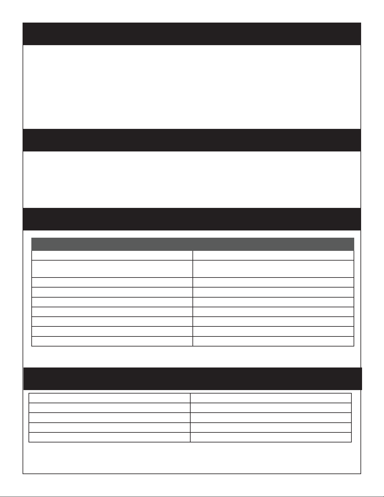
Installation Requirements
Item Description
Concrete Enough for 10” Deep, 3’ square slab
Mounting Hardware Kit ABLTMHE (Existing Slab) or
ABLTMHN (New Slab)
#1 Phillips Screwdriver -
1/4” Driver -
Security Torx Bit Provided by Alpha. For access panels 2, 3 and 4.
Adjustable Wrench
1/4” Spanner Adapter for 1/4” Driver Provided by Alpha. For access panel 1.
Analog Phone Line * If Using 900mHz or Land Line
Phone Cable * If Using 900mHz or Land Line
Tower Dimensions
Height 9 ft.
Width 10.75 in.
Depth 6 in.
Steel Thickness 11 Gauge
Weight 167 lbs.
Page 2
Page 3
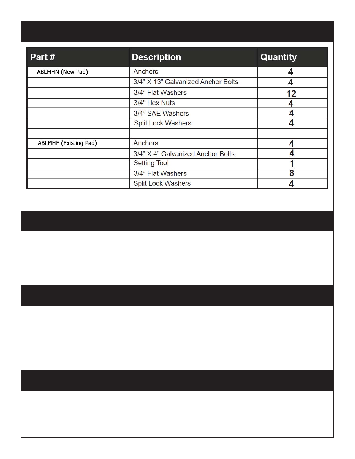
Mounting Hardware
Tower Installation
1. Lay Tower on its side with the base next to the concrete pad
2. Open Lower Access Panel 4 on back of Tower (See Figure 1)
3. Feed the electrical and phone wires in the conduit into the Tower base through the 4” hole
4. Align the Tower mounting holes with the four 3/4” galvanized rods and lift on to the concrete slab
5. Put a lock washer on each rod along with a nut and secure tightly
Connecting the Electric Lines
1. Locate the black (positive) and white (negative) wires that exit the NEMA 4 box in the Tower
2. Connect the electrical wires from the conduit to the wires in the Tower using the waterproof wire nuts located
on the wires
Note: Alpha off ers 120V, 277V, or 480V as power options. Power preference should be disclosed at point of sale and
corresponding transformer will be installed in Tower.
Connecting the Phone and Turning On the Electric Power
1. Locate the gray phone cable coming out of the NEMA 4 box
2. If using an analog phone line for communication, connect tip and ring from phone line run through conduit
to red and green phone cable coming out of the NEMA 4 box (Note: If using a cellular or 900mHz, phone line
should already be connected within Tower).
3. Turn on the electrical power
Page 3
Page 4

Communication Options
Land Line
To connect your analog phone line to the Emergency Tower:
1. Open Access Panel 3 (Figure 1) using the security torx bit to remove the security screws.
2. Locate the gray phone cable coming out of the NEMA box.
3. Connect the gray phone cable to the phone cable that was run through the conduit either by connecting the
modular jack or the Red and Green wires.
GSM Cellular
1. Open Access Panel 2 (See Figure 1) using security torx bit to remove security screws.
2. Remove the cover of the NEMA 4 enclosure.
3. Locate the Cellular Module inside the enclosure.
4. When the “PWR”, “RDY” and “NW” lights on the front of the unit are illuminated, unit is ready.
5. Verify Phone is plugged into the FXS port on Cellular Module.
NOTE: If the Sim Card is not provided to Alpha at time of purchase, an active Sim Card will need to be installed into
Sim Card slot in cellular unit. When installing Sim Card, disconnect power from cellular unit, install Sim Card in Sim
Card slot, then reapply power.
CDMA Cellular
1. Open Access Panel 2 (See Figure 1) using security torx bit to remove security screws.
2. Remove the cover of the NEMA 4 enclosure.
3. Locate the Cellular Module inside the enclosure.
4. When “Power”, “Signal Strength”, and “”Service Indicator” lights are all illuminated solid, unit is ready.
5. Verify Phone is plugged into the phone port on Cellular Module.
2-Way Radio
The 2-way radio phone can both transmit and receive voice communications. Our 2-way radios are fi xed in the
Tower and must be programmed to the specifi cs of the 2-way system in use within the facility or campus. The 2-way
radio is programmed at the factory using customer provided information (Frequency, Squelch code, and narrow or
wide bandwidth). The antenna is installed and tuned at the factory. Towers using 2-way radio are not ADA compliant (the button must be pushed and held to talk and let go to listen).
NOTE: Emergency Towers using 2-way radios are not programmable. Sections in this manual on Programming
the Phone do not apply.
Adjusting the Tower Volume for 2-Way Radio
1. If the volume of the Tower needs to be adjusted, remove Access Panel 3 located on the back of the Tower
(Figure 1).
2. Open the NEMA box to access the radio. Turn the radio volume control up or down to adjust the volume.
3. Close the NEMA box and reattach Access Panel 3.
900 Mhz
Each Tower includes (2) 900 mHz units, 1 Remote Station, and 1 Base Station. The Remote Station is already installed in the Tower.
1. Locate the 900 mHz unit with Base Station labeled on the bottom.
2. Screw black antenna into back of 900 mHz Base Station.
3. Plug dedicated analog phone line or analog extension off of a PBX system into the port labeled “Line”.
4. Connect Power Cable included with unit into DC input on Base Station and a 120vac outlet.
5. Test units by taking an analog phone and plugging it into the “Line” Port on Remote Station installed in the Tower. There should be a dial tone and you should be able to place a call out.
6. Verify Phone is plugged into “Tel” Port on Remote Station. Phone is now ready for programming.
NOTE: If installing multiple 900 mHz units, please put a minimum of 3 feet between each Tower. Connect one unit
at a time, test, and then continue adding one unit and testing until all units are ready and functional.
Page 4
Page 5

Programming the Phone (Cont’d)
1. You can program the phone on-site or remotely. Note: Cellular and 900mHz applications cannot be remotely
programmed.
2. If programming on-site, open back access panel 3 located directly behind the front stainless steel face plate.
Use the #10 spanner bit provided to remove the 6 security screws.
3. Remove the cover of the NEMA 4 enclosure by loosening the 4 corner screws.
On-Site Programming
Step 1. To Begin Program Mode
A. Press Enter
Step 2. To Program Emergency Numbers
A. Press 1, Enter, (phone number), Stop
Note: Press 2-5 in step 2A for Emergency Numbers 2-5 as needed
Step 3. To Program Location Message
A. To turn on message Press 1, 3, Enter, 2
B. Press 6, Record (speak message) Stop (to replay message Press 6, Play)
C. For no message Press 1, 3, Enter, 0
Step 4. To Program Auto Disconnect Time (Default is 5 minutes, lowest interval is 1 minute)
A. Press 8, Enter, (3 Digit number in minutes)
Ex: 2 minutes = 002
Step 5. To Exit Program Mode
A. Press Stop for 3 seconds
Remote Programming
Step 1. To Begin Program Mode
A. Call into phone by dialing the number of the tower
B. After 1st simulated ring Press #, # (Wait for 4 tones)
C. Key in security code (Default is 1111) (Wait for confi rmation tones)
Step 2. To Program Emergency Numbers
A. Press 1, *, (Phone number), *, # (Wait for confi rmation tones)
Note: Emergency numbers (2-5) Repeat Step 2A pressing (2-5) as needed
Step 3. To Program Location Message
A. To turn on message Press 1, 3, *, 2 (Wait for confi rmation tones)
B. Press 6, *, (Speak message) #, *, # (Wait for confi rmation tones)
a. To replay message press 6, # (Wait for confi rmation tones)
C. For NO message press 1, 3, *, 0 (Wait for confi rmation tones)
Step 4. To Program Auto Disconnect Time (Default is 5 minutes, lowest interval is 1 minute)
A. Press 8, *, (3 Digit number in minutes)
Ex: 2 minutes = 002
Step 5. To Exit Program Mode
A. Press *, #, 0 (You will hear a beep, beep) *, # (You will hear a buzz)
Page 5
Page 6

Testing The Phone
Push the silver emergency button on front of the Tower
Adjusting The Volume
If the volume is too low or high, adjust it by referring to the diagram and instructions below. Note: Refer to the
instructions under “Programming the Phone” to access the circuit board.
Adjusting The Microphone
If the person you are calling reports your voice is not loud enough, increase the Microphone Sensitivity by adjusting
VR2 1/4 turn clockwise (requires a small Phillips screwdriver).
Adjusting The Speaker
If the voice of the person you call is not loud enough in the emergency phone speaker, increase the volume by adjusting VR1 1/4 turn clockwise. Reinstall the cover on the NEMA enclosure and secure the rear access panel.
Suggested Ongoing Testing of the Phone
We recommend that the Emergency Tower be tested and maintained on a regular basis to ensure proper operation.
For testing, follow the procedure outlined in “Testing of the Phone”.
Page 6
Page 7

Troubleshooting
Page 7
Page 8

Wiring Diagram
Page 8
 Loading...