

Page 1
Installation Instructions
Alpha Top Easy-Flue 500 mm
(Kit Part No. 1000377)
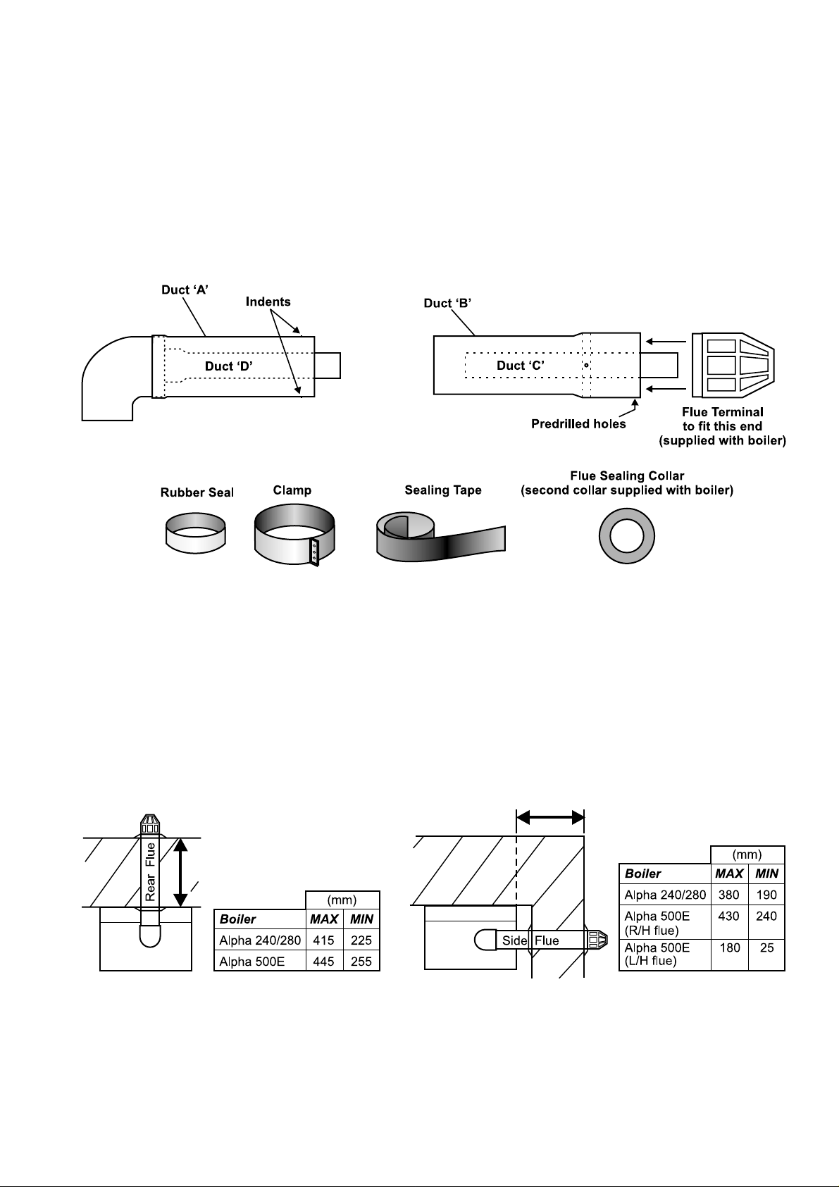
KIT CONTENTS
1. GENERAL
a. The Alpha Easy-Flue is suitable for straight horizontal flues only and can be extended up to the maximum lengths
given in Fig. 1 and 2.
b. The Easy-Flue includes a 90° bend, (no separate 90° bend is required).
c. Ensure that there is a slight downward slope of the flue to outside.
d. The flue system must be installed in accordance with BS 5440:1:1990.
e. The Easy-Flue is suitable for use in the flue length ranges given in Fig. 1 and 2.
Fig. 1 - Rear Flue Fig. 2 - Side Flue
Note: Where the length is less than the minimum or more than the maximum, refer to Appendix 2.
Page 2
2. INSTALLATION INFORMATION
a. Use the template (supplied with the boiler) to mark the flue position and cut a 130 mm diameter hole for the flue (use
a 127 mm core drill). This size of hole provides sufficient room for the flue to be fitted to the top of the boiler.
Note: If a 110 mm hole is cut for the flue, it is difficult to locate the flue onto the boiler flue adaptor, disconnect the duct
from the bend by removing the fixing screw. After installation ensure the duct is re-assembled onto the bend correctly.
Mount the boiler on the wall as described in the boiler Installation and Servicing instructions.
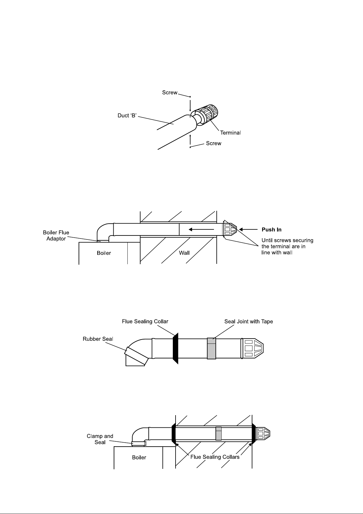
b. Fit the flue terminal (supplied with the boiler) to the enlarged end of Duct 'B'. Secure with two screws supplied with
the terminal as shown in Fig. 3.
Fig. 3
c. Extend the telescopic flue to its full length. From the inside, pass the assembly through the wall. Seat the flue bend
onto the boiler flue adaptor.
d. From outside, push the terminal in towards the wall until the screws securing the terminal are in line with the outside wall.
See Fig. 4.
Note: If there is no access to the outside wall, refer to Appendix 1.
Fig. 4
e. Carefully remove the flue assembly from the wall. Seal and secure the joint between the ducts with the sealing tape
supplied.
f. Position the rubber seal over the 90° bend as shown in Fig. 5.
g. Fit the inside flue sealing collar over the flue, see Fig. 5. From the inside, pass the flue assembly through the wall.
Fig. 5
h. Secure the 90° bend to the boiler using the clamp and rubber seal. Ensure that the seal covers the bend and adaptor
joint. See Fig. 6.
i. Make good the inside and outside walls with the flue collars. See Fig. 6.
Note: The second flue collar is supplied with the boiler.
Alpha Top Easy-Flue
2
Fig. 6
Page 3

Appendix 1 - Installation from inside the building (no access to outside wall).
a. Using the tables below, determine the flue length (L) required. See Fig. 7.
Fig. 7
Alpha 240/280 Range
Rear Flue L = Wall thickness + 230 mm
Side Flue L = Wall thickness + distance between boiler and wall + 265 mm
Alpha 500E
Rear Flue L = Wall thickness + 200 mm
Side Flue (to right) L = Wall thickness + distance between boiler and wall + 215 mm
Side Flue (to left) L = Wall thickness + distance between boiler and wall + 465 mm
b. Adjust the flue to the distance 'L' then seal and secure the joint between the ducts with the sealing tape supplied.
c. Position the rubber seal over the 90° bend as shown in Fig. 7.
d. Fit the inside flue sealing collar over the flue. Fit the second flue sealing collar (supplied with the boiler) onto the flue
immediately before the terminal. Push the flue assembly through the hole, so that the collar completely passes
through the wall. Then pull back into the correct position. See Fig. 8.
Fig. 8
e. Secure the 90° bend to the boiler using the clamp and rubber seal. Ensure that the seal covers the bend and adaptor
joint. See Fig. 9.
f. Make good the inside wall by pushing the inside collar up to the wall.
Fig. 9
Alpha Top Easy-Flue
3
Page 4

Appendix 2 - When the flue length required is less than the minimum or more
than the maximum stated in Fig. 1 and 2.
Rear Flue Side Flue
Fig. 10
Alpha 240/280 Range
Rear Flue Side Flue Comments
Up to Max:- 3890 mm 3855 mm Alpha 750 flue extension (Part No. 1000320) is required
to extend the range of the telescopic flue. Refer to
Appendix 3 for instructions on how to extend the flue.
Note: A 130 mm flue hole (127 mm core drill) is required
in the wall.
Between:- 225 mm
and 415 mm
Less than:- 225 mm Terminal may protrude somewhat from the outside wall.
But if it is:-
105 mm
or less
190 mm
and 380 mm
190 mm
70 mm
or less
Within the standard telescopic range.
Discard Ducts 'B' and 'C' and fit the terminal to Duct 'A' (small
indents marked on Duct 'A' indicate where to drill 4 mm
holes for the terminal fixing screws.
Alpha 500E
Rear Flue RH Side Flue Comments
Up to Max:- 3920 mm 3905 mm Alpha 750 flue extension (Part No. 1000320) is required
Between:- 255 mm
and 445 mm
Less than:- 255 mm Terminal may protrude somewhat from the outside wall.
240 mm
and 430 mm
240 mm N/A
LH Side Flue
3655 mm
25 mm
and 180 mm
to extend the range of the telescopic flue. Refer to
Appendix 3 for instructions on how to extend the flue.
Note: A 130 mm flue hole (127 mm core drill) is required
in the wall.
Within the standard telescopic range.
But if it is:-
Alpha Top Easy-Flue
4
135 mm
or less
120 mm
or less
N/A
Discard Ducts 'B' and 'C' and fit the terminal to Duct 'A' (small
indents marked on Duct 'A' indicate where to drill 4 mm
holes for the terminal fixing screws.
Page 5

Appendix 3 - Extending the Top Easy-Flue 500
a. Use the template (supplied with the boiler) to mark the flue position and cut a 130 mm diameter hole for the flue (use
a 127 mm core drill). This size of hole provides sufficient room for the flue to be fitted to the top of the boiler.
Mount the boiler on the wall as described in the boiler Installation and Servicing instructions.
b. Fit the flue terminal (supplied with the boiler) to the enlarged end of Duct 'B'. Secure with two screws supplied with
the terminal as shown in Fig. 11.
Fig. 11
c. Remove the Duct B assembly from Duct A by pulling in the direction of the arrows. See Fig. 12.
Fig. 12
d. Fit a 750 flue extension (Part No. 1000320) to Ducts A and D using the clamps and seal supplied, as shown in Fig. 13.
Connect any additional extension in the same way.
Note: Ensure that the end of the outer duct with the two holes is connected to Duct A.
Fig. 13
e. Continue to add flue extensions until the assembly is within 200 mm of the outside wall, ensuring that the overall
maximum length with Duct B fitted, will not be more than that given in Appendix 2.
Note: To gain the correct length, only cut the flue extension ducts (ensure that the cuts are square, free from burrs
and the ducts are not distorted). Do Not cut the Easy-Flue ducts.
Alpha Top Easy-Flue
5
Page 6

f. Engage Duct 'B' into the flue extension as shown in Fig. 14. Duct B goes inside Duct A and Duct C goes over Duct D.
Note: If there is any difficulty in locating the ducts together, ensure that all engaging ducts have no burrs and are not
distorted.
Fig. 14
g. When the telescopic section of the flue has been adjusted to the correct length, seal and secure the joint with the
sealing tape supplied. See Fig. 15.
Important Note: Ensure that the inner duct is connected securely throughout the flue assembly.
Fig. 15
h. Continue to fit the complete assembly to the boiler as described in section2, paragraphs f to i.
Alpha Therm Limited.
Nepicar House, London Road, Wrotham Heath
Sevenoaks, Kent TN15 7RS
email: info@alphatherm.co.uk
website: www.alpha-innovation.co.uk
Compiled and designed by Publications 2000, Tel (01670) 356525
These guidelines have been carefully prepared but we reserve the right to
alter the specification at any time in the interest of product improvement.
© Alpha Therm Limited 1999.
Part No. 0001126
07/99/D117
 Loading...