

Page 1
TPL Series Emergency Tower Phones
Installation & Operations Manual
REQUIRED ITEMS
PROVIDED BY ALPHA
• Alpha BlueLight™ Emergency Tower
• Strobe
• NEMA 4 electrical box (mounted inside Tower Phone)
• Transformer
• Voltage regulator
• Torx bit
NOT PROVIDED BY ALPHA
• 110v power source
• Dedicated analog phone line or analog extension off of a PBX
• Phillips screwdriver
• 1/4” driver
AWD193
Rev 1
07/2014
SITE PREPARATION
1. Trench in for power and phone line
2. Dig a 3’ x 3’ square “pad” that is a minimum of 8-10” deep
3. Pour concrete a minimum of 8” deep and 3’ x 3’ square
4. Insert the 3/4” x 12” galvanized rods using the provided mounting template (A minimum of 2” of thread must be exposed above level of concrete)
5. Position conduit that will contain the electrical and phone wiring into center of the
concrete pad using the mounting template
6. When running the wire, provide at least 48” of wiring above the concrete pad
7. Let concrete set for a minimum of 48 hours
TOWER INSTALLATION
1. Lay tower on its side with the base of the tower next to the concrete pad.
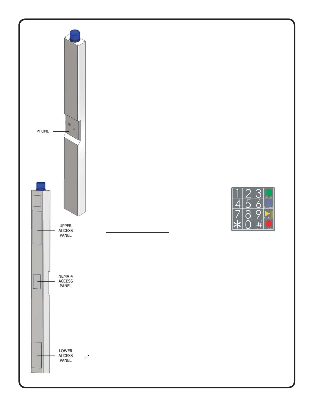
2. Open the NEMA 4 access panel and locate the gray Wago Connectors.
3. Disconnect the Wago Connectors
4. Open the bottom access panel
5. Feed the electrical and phone wires in the conduit into the tower base through the 4”
hole
6. Align the tower mounting holes with the four ¾” galvanized rods and lift on to the
concrete slab
7. Put a lock washer on each rod along with a nut and secure tightly
Alpha Communications • 42 Central Drive • Farmingdale NY 11735-1202
Toll-Free Technical Line 1-800-666-4800 • Phone: (631) 777-5500 • Fax: (631) 777-5599
Web: www.alphacommunications.com
Due to continuous product improvement, all colors, sizes, wiring and specifi cations are subject to change without notice.
©Copyright 2014 Alpha Communications®. All Rights Reserved.
• Email: info@alphacommunications.com
Page 1
Page 2
CONNECTING THE ELECTRIC LINES
1. Locate the black (positive) and white (negative) wires that exit the NEMA 4 box in
the tower
2. Connect the electrial wires from the conduit to the wires in the tower using the
waterproof wire nuts located on the wires
CONNECTING THE PHONE AND
POWERING ON THE ELECTRIC
1. Locate the gray phone cable coming out of the NEMA 4 box
2. Connect the cable to the phone cable that was run through the conduit
3. Reconnect the Wago connector located behind the faceplate
4. Turn on the electical power
PROGRAMMING THE PHONE
1. You can program the phone on-site or remotely.
2. If programming on-site, open back access panel
located directly behind front stainless steel face
plate. Use the #10 spanner bit provided to remove the 6 security screws.
3. Remove the cover of the NEMA 4 enclosure by
loosening the 4 corner screws.
ONSITE PROGRAMMING
1. To Begin Program mode Press Enter
2. To Program Emergency Numbers Press 1, Enter, (phone number), Stop
(Note: Press 2-5 in step 2 for Emergency numbers 2-5 as needed)
3. To Program Location message
A. To turn on message Press 1, 3, Enter, 2
B. Press 6, Record (speak message) Stop
(to replay message Press 6, Play)
C. For no message Press 1, 3, Enter, 0
4. To exit program mode Press Stop for 3 seconds
REMOTE PROGRAMMING
1. To Begin Program mode
A. Call into phone by dialing the cellular number of the tower
B. After 1st simulated ring Press #, # (Wait for 4 tones)
C. Key in security code (default is 1111) (Wait for confi rmation tones)
2. To Program Emergency Numbers
A. Press 1, *, (Phone number), *, # (Wait for confi rmation tones)
Note: Emergency numbers (2-5) Repeat Step 2A; pressing (2-5) as needed.
3. To Program Location Message
A. To turn on message Press 1, 3, *, 2 (Wait for confi rmation tones)
B. Press 6, *, (speak message) #, *, # (Wait for confi rmation tones)
a. (to replay message press 6, #) (Wait for confi rmation tones)
C. For NO message Press 1, 3, *, 0 (Wait for confi rmation tones)
4. To Exit Program Mode
A. Press *, #, 0 (you will hear beep, beep) *, # (You will hear a buzz)
Page 2
Page 3

TESTING OF THE PHONE
Push the silver Emergency Button on the front of the Call Tower
Do you hear a dial tone?
Does the Strobe start fl ashing immediately when button was pushed?
Does red LED become a solid light when you pushed the button?
Does the red LED fl ash and a short time after (15-20 seconds) the called party started talking to you?
(Delay is due to phone telling other party your location via the “Location Message”)
Can you hear the other party clearly? (if no, see “Adjust Speaker” on the next page)
Can the other party hear you clearly? (If no, see “Adjust Microphone” on the next page)
When the party you called hangs up, does the strobe stop?
If you have answered YES to all questions, you have successfully installed and tested your new
emergency phone. If you answered no to any question, proceed to the Troubleshooting section.
ADJUSTING THE VOLUME
If the volume is too low or high, adjust it by referring to the diagram and instructions below.
*Note - Refer to the instructions under “Programming the Phone” to access the circuit board.
YES NO
Adjusting the Microphone:
If the person you are calling reports your voice is not loud enough, increase the Microphone Sensitivity by adjusting VR2 ¼
turn clockwise (requires a small Phillips screwdriver).
Adjusting the Speaker:
If the voice of the person you call is not loud enough in the emergency phone speaker, increase the
volume, by adjusting VR1 ¼ turn clockwise. Reinstall the cover on the NEMA enclosure and secure the rear access panel.
SUGGESTED ONGOING PHONE TESTING
It is recommended that the Emergency Call Station(s) be tested and maintained on a monthly basis to ensure proper operation. For testing, follow the procedure outlined in “Testing of the Phone”.
Page 3
Page 4

TROUBLESHOOTING
PROBLEM POSSIBLE CAUSE & FIXES
No dial tone when the button is pushed • Check to make sure the phone line is connected.
• Verify dial-tone and voltage on phone line going into unit.
Audio is low from the speaker • Speaker control needs to be adjusted. Go to Adjusting the
Speaker on page 3.
• Make sure the speaker holes are not blocked.
Audio is distorted from the speaker • Speaker control needs to be adjusted. Go to Adjusting the
Speaker on page 3.
• Make sure there are no items touching the speaker inside the
tower.
Called Party says audio is low • Microphone control needs to be adjusted. Go to Adjusting
the Microphone section on page 3.
• Make sure the microphone hole is not blocked.
When called party hangs up, strobe continues to fl ash for 1 minute:
When called party hangs up, strobe continues to fl ash:
Tower appears nonfunctional. Strobe
does not fl ash and no audio is heard
from speaker when button is pushed
• Slow disconnecting signal from the phone company. This is
considered normal operation
• Phone company or phone system is not providing a disconnect
signal. Contact the appropriate party to make sure the disconnect signal is provided.
• Check to make sure phone line is connected.
• Double check electrical connections.
• Push button may be nonfunctional.
EMERGENCY TOWER DIMENSIONAL SPECS
Page 4
 Loading...