

Page 1
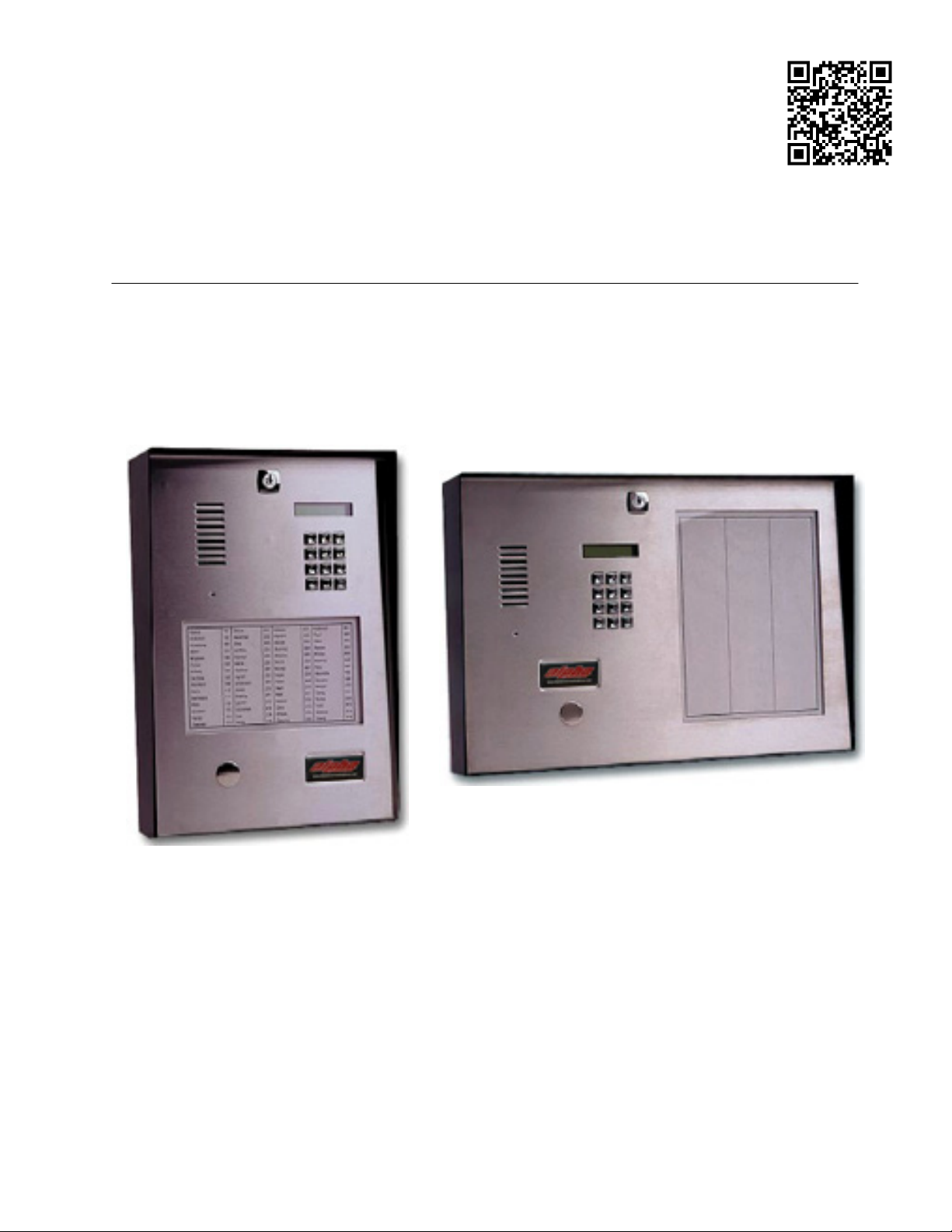
ALPHAGUARD 2000
TELEPHONE-ENTRY AUTODIALER
INSTALLATION & PROGRAMMING MANUAL
AWD165 Rev. 1 09/2012
Page 2

Page 3

ALPHAGUARD 2000 Series Autodialer
SYSTEM FEATURES
Capacity for up to 1000 Tenants.
Simple Upgrade from Autodialer to No Telephone Line System.
Handsfree or Handset operation.
Field Programmability using system keypad.
High Contrast LCD user Display.
Zinc Die-cast Marine Quality Keypad.
2
E
PROM Memory, retains programmed information during total power failure.
Superior Lightning & Transient Protection.
Two Programmable Relay outputs to control door strikes, gates, cameras, etc.
System operates with both Tone and Pulse telephones.
Variable Tenant Code length, 1, 2, 3, or 4 digits
7, 10 and 11 Digit dialing capability.
Built-in Multiple Entrance capability.
Automatic termination of call after eight seconds of dial tone detection.
Tone & Tapping Rejection Circuitry to prevent unauthorised entry.
Provision for Postal Service Lock included.
Contact Input will pulse entry doors during an emergency.
Door Timer Cutoff input prevents 'tail-gating' through entry doors.
Night Service Feature, transfers all calls to pre-programmed telephone number.
One 'Keyless' Entry Code per tenant plus five for use by building management.
Warning Tone to alert tenant call will end in 10 seconds.
Tenant Codes can be actual suite numbers or may be coded for security purposes.
Page 4

ALPHAGUARD 2000 Series Autodialer
Installation Manual for 2000 Series Telephone-Entry Autodialer
TABLE OF CONTENTS
Page
1.0 Installation Hints .................................................................................................. 1
2.0 Special Features ................................................................................................. 1
2.1 Postal Service Lock ............................................................................................. 1
2.2 Door Timer Cut-Off .............................................................................................. 1
2.3 Auxiliary Relay Activation ...................................................................................... 2
2.4 Emergency Input ................................................................................................. 2
2.5 Multiple Entrances ............................................................................................... 2
2.6 Night Service ..................................................................................................... 2
3.0 Installation ............................................................................................................ 3
4.0 System Programming .......................................................................................... 4
4.1 Entering/Exiting "Program" Mode ........................................................................ 4
4.2 Tenant Codes, Entry/Review/Delete .................................................................... 4
4.3 Keyless Entry Codes ............................................................................................ 5
4.4 System Master Code ........................................................................................... 6
4.5 7, 10, 11 Digit Select ............................................................................................ 6
4.6 Telephone Line Type Selection ............................................................................ 6
4.7 Door Timer Selection ........................................................................................... 7
4.8 Conversation Time Selection ............................................................................... 7
4.9 Night Service ........................................................................................................ 7
4.10 Night Service Telephone ...................................................................................... 7
5.0 Adjustments ......................................................................................................... 8
5.1 Volume Controls .................................................................................................. 8
5.2 Rotary Phone (Pulse) Sensitivity ......................................................................... 8
Appendices
A. Regulatory Approvals and System Warranty
B. System Wiring Diagram
C. Programming Worksheet
D. Directory Worksheets
E. User Instruction Sheet
G. F. Wiegand Card Access Interface
© 1999, E S & P Ventures Corp.
Page 5

ALPHAGUARD 2000 Series Autodialer
1.0 INSTALLATION HINTS
Arrangements should be made with the telephone company for the installation of a telephone line
for use by the system. It is recommended that the telephone jack be installed inside the entry
panel enclosure.
One 16 Volt/20 VA CSA approved Class 2 power transformer is required for system operation. A
second transformer is required for door strike activation. This transformer should have the
necessary voltage and current rating for the door strike that is to be used. Do not exceed the
maximum relay rating of 3 amps @ 28VDC.
Transformers and remote devices such as the door strike, emergency and door contacts, must be
wired to the system controller located in the enclosure housing. A wiring channel must be
provided for these devices to the rear of the system enclosure. Follow local building code
requirements for low voltage wiring.
If a Postal Service Lock is to be installed, arrangements must be made with Post-Office to have the
lock supplied.
In Multiple Entrance applications, two additional wires are required from each entry system
to interconnect the system controllers. A telephone line extension jack must also be installed at
each entry location (see system wiring diagram).
2.0 SPECIAL FEATURES
2.1 Postal Service Lock
Provision for the installation of a Postal Service Lock is available on the rear of the control panel of the
system enclosure. The system is pre-wired for this service.
2.2 Door Timer Cut-Off
Using this feature of the entry system will require the installation of a Normally Open switch contact that
closes when the entry door has been opened. A magnetic contact, as used in security systems is
acceptable for this application provided that a Normally Open type is obtained.
When the electric door strike is released, the door will normally remain open for the period of time that
has been programmed (see Door Timer Selection, Sec.4.7). When the door timer cut-off feature is used,
the door strike will de-energize as soon as the system senses that the entry door has been opened. This
will cause the door to lock when it closes regardless of the programmed time. This action will allow the
door strike to be energised only as long as necessary and will prevent unauthorised entry of individuals
who follow behind the visitor (tailgating).
1
Page 6

ALPHAGUARD 2000 Series Autodialer
2.0 SPECIAL FEATURES
2.3 Auxiliary Relay Activation
The system includes a Form C auxiliary relay contact that can be momentarily activated from the suite
telephone by dialing the digit 6 when the tenant is in conversation with the visitor at the entry system. This
contact can be used to trigger a parking gate, elevator, secondary door or video camera.
2.4 Emergency Input
Connection of a Normally Open alarm contact will cause the electric door strike to pulse on and off in the
event of an emergency situation. This will effectively leave the entry door unlocked for the duration of the
emergency.
2.5 Multiple Entrances
Accommodation of multiple entry doors is a built-in feature of the AlphaGuard System. Up to 20 entry
systems can be interconnected without the need for additional switching equipment, and all systems can
be connected to one common telephone line. One additional pair of wires, parallel connected, to terminals
ME and G of all entry systems will be required. When one entry panel is in use, the other panels will be
temporarily disabled and display a "System in Use" message. Note that each entry panel must be
independently powered and programmed, and requires a telephone extension jack at that location.
2.6 Night Service
When enabled, the Night Service feature can be used to redirect all entry system calls to a pre-
designated telephone number (Guard Phone). When in use (by entering * 4 5 6), the entry system will
display the "Night Service On" message. To return to normal, re-enter * 4 5 6.
(cont.)
2
Page 7

ALPHAGUARD 2000 Series Autodialer
3.0 INSTALLATION
1. Mount the system enclosure to the wall in a location close to the building's controlled entry point.
1. Connect the door strike wires to terminals D1 and D2 for D.C. (silent) operation or to terminals D3 and
D4 for A.C. (buzzing) operation. Do not exceed maximum switched door strike load of 28 volts at 3
Amps.
1. An auxiliary switched device may be controlled through the auxiliary relay contact that is available by
connecting to terminals N.C.(normally closed), C (common) and N.O.(normally open).The maximum
switched auxiliary load is 28 volts at 3 amps. This contact will change state for one second, when
energized by the tenant dialing the digit 6 from their suite telephone. (Tone type phones only).
1. Terminal PL is for the postal service lock. Closing of a normally open switch between terminals PL and
G is required for activation. Remove the panel plug button for the Postman's key and mount the lock
with the supplied hardware. Adjust the switch actuator for proper operation with the lock. Attach wires
from switch to terminals PL & G on controller.
1. Terminal TC is for connection of a door timer cut-off contact. A normally open contact that closes when
the door has been opened will cut-off the door timer and instantly re-lock the door. This is used to
prevent "tail-gating" of unwanted visitors through the entry doors.
Connect between terminals TC and G.
1. Terminal FA is for connection to the building emergency contact. A normally open contact that closes
during an alarm condition can be connected between terminals FA and G to pulse open the entry door
during an emergency situation.
7. Terminal ME is the interconnect point for multiple entrance systems. Terminals ME and G of all entry
systems must be interconnected from each entry system to allow operation with a common telephone
line. Each location must also be wired with its own transformer, door strike, extension telephone jack,
switch contacts, etc. as shown on the wiring diagram. Each location must be separately programmed.
8. Connect door strike transformer to terminals T3 and T4. Note that the maximum door strike load that
may switched through the controller is 28 volts at 3 amps.
8. At this time all wiring should be checked for shorts and opens. Connect 16 VAC from system
transformer to terminals T1 and T2 on system controller terminal block. This transformer must not be
used to power any other devices such as the door strike. The display should now be illuminated and
the message " Welcome, Dial Code Number " will appear. Telephone Line may now be connected.
- Refer to SYSTEM WIRING DIAGRAM (Appendix B)
3
Page 8

ALPHAGUARD 2000 Series Autodialer
4.0 SYSTEM PROGRAMMING
All programming of the entry system is accomplished through the use of the system keypad and the
display located on the control panel. Use the supplied Directory Worksheets to generate a record of the
building occupants, their suite telephone numbers, assigned dial codes and keyless entry codes. These
sheets will be required for programming and in the event that changes are to be made.
Complete the Programming Worksheet that has been provided and ensure that this and the directory
worksheets are given to building management when installation and programming is completed.
4.1 Program Mode Entry / Exit
Enter the three digit System Master Code (default is * 1 2 3) to commence a programming session. Use
the '1' key on the keypad to scroll up the programming menu or the '3' key to scroll down to the necessary
function. When the necessary function is displayed on the screen, press the '#' key to select. Follow the
displayed instructions to make the necessary changes. When programming is complete, exit program
mode by pressing the '*' key twice.
4.2 Tenant Codes Entry / Review / Delete
Tenant Code Entry
Press '#' key to select this function when the program menu displays "TO PROGRAM CODES, PRESS
#". This function allows the entry of the tenant codes and telephone numbers. Enter the four digit tenant
code followed by the tenant telephone number (7, 10 or 11 digit telephone numbers can be
accommodated, see section 4.5). Press the '#' key to store the numbers. Continue in this fashion until all
codes and telephone numbers are stored. If the tenant codes are less than four digits in length, enter
zeroes as leading digits in the code , they will be ignored by the system during actual use but are required
for programming. If an error is made while entering a code or a telephone number, press the '*' key to
backspace.
Press the '*' key when finished to exit this mode and return to the programming menu.
Press the '*' key to exit the program mode if desired.
4
Page 9

ALPHAGUARD 2000 Series Autodialer
Tenant Code Review and Delete
Press the '#' key to select this function when the program menu displays " VIEW TENANT CODES". The
message "CODE TO REVIEW, ______" will appear. Enter the four digit code to be reviewed. The code
and associated telephone number will then appear on the display. If the code and telephone number are
to be deleted, press the '#' key while they are being displayed. From this point is also possible to display
all tenant codes and telephone numbers by using the '1' and '3' keys to scroll through the memory.
Press the '*' key when finished to exit this mode and return to the programming menu.
Press the '*' key to exit the program mode if desired.
4.3 Keyless Entry Codes - Entry / Review / Delete
Entry of Keyless Entry Codes
Keyless Entry Codes allow entry through the controlled doors by the use of a four digit code from the
system keypad. This code must be preceded by the '#' key during actual use so that the code is not seen
on the display.
Press the '#' key to select this function when the programming menu displays "ENTER KEYLESS
CODES". The message "KEYLESS ENTRY, CODE # _______" will appear so that codes may be
entered. Use the '#' key to store the code.
Press the '*' key when finished to exit this mode and return to the programming menu.
Press the '*' key to exit the program mode if desired.
Keyless Entry Code Review and Delete
This section allows the review and/or deletion of keyless entry codes. Press the '#' key to select this
function when the programming menu displays the message "VIEW KEYLESS CODES". The message
"CODE TO REVIEW _____" will appear. Enter the code to be reviewed. Use the '1' and '3' keys to scroll
through the memory and view the assigned codes. If a code is to be deleted, press the '#' key while the
particular code is being displayed.
Press the '*' key when finished to exit this mode and return to the programming menu.
Press the '*' key to exit the program mode if desired.
5
Page 10

ALPHAGUARD 2000 Series Autodialer
4.4 System Master Code
The Master Code is used to allow access to the "Program Mode". When the entry system is shipped from
the factory, its master code is set to * 1 2 3 . It is recommended that the master code be reprogrammed
and the new code be inserted in the appropriate place on the Programming Worksheet (Appendix C).
This code is only to be used when programming is necessary by the installation company or by
authorised personnel.
The Master Code can be reset to * 1 2 3 by shorting the pins marked “Reset Master Code” on the system
controller with a key or small screwdriver while power is on. This will not alter any other programmed
information.
Press the '#' key to select this function when the programming menu displays the message “NEW
MASTER CODE". The message "MASTER CODE * 1 2 3" will appear. Enter a new 3 digit master code
and then press the '#' to store. The new master code will now be required to access the programmable
functions.
Press the '*' key when finished to exit this mode and return to the programming menu.
Press the '*' key to exit the program mode if desired.
4.5 7, 10 or 11 Digit Dialing
AlphaGuard autodialers allow for dialing of 7, 10 and 11 digit tenant telephone numbers. From the menu,
press the ‘#’ key to select the number of digits required. Different length numbers can be intermixed by
using this section as required.
Press the '*' key when finished to exit this mode and return to the programming menu.
Press the '*' key to exit the program mode if desired.
4.6 Telephone Line Type Selection
This section will select the type of dialling the system controller will use, DTMF or Pulse (factory default is
DTMF). The setting must correspond with the type of telephone line that has been installed for the entry
system.
Press the '#' key to select this function when the programming menu displays the message "PULSE OR
TONE OPTION". The message "PULSE OR TONE' will appear on the display. Enter '0 0' for Pulse
(Rotary) or '1 1' for Tone (DTMF) type dialling.
Press the '*' key when finished to exit this mode and return to the programming menu.
Press the '*' key to exit the program mode if desired.
6
Page 11

ALPHAGUARD 2000 Series Autodialer
4.7 Door Timer Selection
The door open time can be selected to be from 0 to 99 seconds, (factory default is 10 seconds).
Press the '#' key to select this function when the programming menu displays the message "DOOR
TIME". The message "DOOR OPEN TIME" will appear. Enter a two digit time in seconds and press the '#'
key to store.
Press the '*' key when finished to exit this mode and return to the programming menu.
Press the '*' key to exit the program mode if desired.
4.8 Conversation Time Selection
This function allows the setting of the conversation time between the visitor and tenant from 0 to 99
seconds, (factory default is 60 seconds). Press the '#' key to select when the programming menu displays
the message "TALK TIME". The message "TALK TIME" will appear. Enter a two digit time in seconds and
press the '#' key to store.
Press the '*' key when finished to exit this mode and return to the programming menu.
Press the '*' key to exit the program mode if desired.
4.9 Night Service
This section will allow enabling or disabling of the Night Service Feature.
See Sections 2.6 and 4.10.
Press the '#' key to select when the programming menu displays the message "NIGHT SERVICE ?”. The
message "ENABLE / DISABLE" will appear. Enter “0 0" to enable the function or “1 1" to disable. Press
the '#' key to store.
Press the '*' key when finished to exit this mode and return to the programming menu.
Press the '*' key to exit the program mode if desired.
4.10 Night Service Telephone
This section allows the programming of the Night Service telephone number when this feature is enabled.
Press the ‘#’ key when the menu displays the message “Program Guard Phone”. Enter the telephone
number where all calls are to be directed when Night Service is enabled.
Press the '*' key when finished to exit this mode and return to the programming menu.
Press the '*' key to exit the program mode if desired.
7
Page 12

ALPHAGUARD 2000 Series Autodialer
5.0 ADJUSTMENTS
5.1 Volume Control
The communication volume levels come factory preset for normal operation. The levels can be increased
or decreased by adjusting the potentiometers located along the bottom of the system controller located
behind the front display plate. Audio level from the entry system to the suite is controlled by the MIC.
VOLUME control and the level from the suite to the entry system by the SPEAKER VOLUME control.
5.2 Rotary Phone Pulse Sensitivity
The telephone companies do not specify or guarantee the waveshape of the signal transmitted when the
tenant dials the digit 9 from a rotary (pulse) telephone. In order to achieve best results, the
System is furnished with a sensitivity adjustment potentiometer as well as an indicator lamp to view the
incoming rotary signal (pulses).
This potentiometer is labelled "PULSE SENSITIVITY" on the system controller. The system sensitivity is
factory preset to allow a wide range of incoming rotary signals to properly trigger the door circuit and
usually will not require any adjustment. If Pulse telephones are not being used, set the sensitivity
adjustment to minimum. If adjustment is necessary because the door strike cannot be properly triggered,
use the following procedure.
1. Set the "PULSE SENSITIVITY" control to mid position.
1. Call the suite telephone that does not properly trigger the door circuit from the entry system.
1. Observe the "PULSE INDICATOR" while the digit 9 is being dialled from the suite telephone. The
indicator should flash distinctly every time a pulse is heard.
1. If the indicator barely comes on, the sensitivity is set too low. Increase the sensitivity by turning the
shaft of the potentiometer clockwise 1/8th of a turn at a time until the indicator shows distinct flashing
and best results are obtained.
1. If the indicator is on steadily, the sensitivity is set too high and the door circuit may false trigger. Turn
the shaft of the potentiometer counter-clockwise to decrease the sensitivity. The sensitivity may also
require reduction if the phone line is particularly loud or noisy.
6. NOTE: Sensitivity adjustments are not required when using tone (DTMF) type suite telephones.
AlphaGuard
8
Page 13

ALPHAGUARD 2000 Series Autodialer
APPENDIX A
REGULATORY APPROVALS
IMPORTANT NOTICE
The following information is provided to the installation contractor for compliance with Industry Canada
Standards.
NOTICE:
The Industry Canada label identifies certified equipment. This certification means that the
equipment meets certain telecommunications network protective, operational and safety requirements.
Industry Canada does not guarantee that the equipment will operate to the user’s satisfaction.
Before installing this equipment, users should ensure that it is permissible to be connected to the facilities
of the local telecommunications company. The equipment must also be installed using an acceptable
method of connection. The customer should be aware that compliance with the above conditions may not
prevent degradation of service in some situations.
Repairs to certified equipment should be made by an authorized Canadian maintenance facility
designated by the supplier. Any repairs or alterations made by the user to this equipment, or equipment
malfunctions, may give the telecommunications company cause to request the user to disconnect the
equipment.
Users should ensure for their own protection that the electrical ground connections of the power utility,
telephone lines and internal metallic water pipe system, if present, are connected together. This
precaution may be particularly important in rural areas.
CAUTION:
Users should not attempt to make such connections themselves, but should contact the
appropriate electric inspection authority, or electrician, as appropriate.
The Load Number (LN) assigned to each terminal device denotes the percentage of the total load to be
connected to a telephone loop which is used by the device, to prevent overloading. The termination on a
loop may consist of any combination of devices subject only to the requirement that the sum of the Load
Numbers of all devices does not exceed 100.
The Load Number for this Equipment is 4.0
Industry Canada Certification No.: 1949 5264 A
ALPHA COMMUNICATIONS® LIMITED WARRANTY
Equipment manufactured by ALPHA is warranted to be free of defects in material and workmanship for a
period of one (1) year from the original shipment date. ALPHA will, at its option, repair or replace any
equipment which it determines to be defective in material or workmanship. Equipment thought to be
defective is to be shipped freight prepaid to ALPHA, ALPHA will prepay return freight. ALPHA shall not be
responsible to repair or replace equipment which has been abused, incorrectly installed, repaired by
others, altered or otherwise misused or damaged in any way. Unless previously contracted by ALPHA,
ALPHA will not assume responsibility for determining the defective or operative status at the point of
installation, and will not assume liability beyond the repair or replacement of the product at our factory or
authorized service centre.
9
Page 14

ALPHAGUARD 2000 Series Autodialer
INSTRUCTION TO THE U.S. USER
FCC REQUIRED INFORMATION
FCC REGULATIONS
This device has been granted a registration number by the FCC, under part 68 rules and regulations
governing devices that directly connect to the telephone lines. This equipment complies with Part 68 of
the FCC rules. A label on the controller housing of the
information, the FCC Registration Number and Ringer Equivalence Number (REN) for this equipment.
You must, upon request, provide this information to your telephone company.
The REN is useful to determine the quantity of devices that you may connect to your telephone line and
still have all of those devices ring when your telephone number is called. In most, but not all areas, the
sum of the REN's of all devices connected to one line should not exceed five (5.0). To be certain of the
number of devices that you may connect to your line, you may want to contact your telephone company
to determine the maximum REN for your calling area.
This equipment may not be used on coin service provided by the telephone company. Connection to
party lines is subject to state tariffs.
Should the
AlphaGuard 2000 cause harm to the telephone network, the telephone company may
discontinue your service temporarily. If possible, they will notify you in advance. But if advanced notice is
not practical, you will be notified as soon as possible. You will be informed of your right to file a complaint
with the FCC. The telephone company may make changes in its facilities, equipment, operations or
procedures that could affect the proper functioning of your equipment. If they do, you will be notified in
advance to give you an opportunity to maintain uninterrupted telephone service.
If you experience trouble with this equipment, please contact:
Alpha Communications®
42 Central Drive
Farmingdale NY 11735-1202
Tel. 631-777-5500 Fax. 631-777-5599
for information to obtain service or repairs. The telephone company may ask that you disconnect this
equipment from the network until the problem has been corrected or until you are sure the equipment is
not malfunctioning.
10
AlphaGuard
2000 contains, among other
Page 15

ALPHAGUARD 2000 Series Autodialer
APPENDIX B
SYSTEM WIRING DIAGRAM
SYSTEM POWER
16 VAC 20 VA
DOOR STRIKE
TRANSFORMER
D.C. (SILENT)
DOOR STRIKE
A.C.(BUZZING)
INTERNAL N.O.
TERM.T4 & D4
DOOR CONTACT
DOOR STRIKE
AUXILIARY RELAY
MOMENTARY CONTACT
POSTAL LOCK
TIMER CUTOFF
COMMON
FIRE ALARM
MULTIPLE ENTRANCE
SYSTEM CONTROLLER
TO (optional) PM900
T1
T2
T3
T4
D1
D2
D3
D4
NO
NC
PL
TC
FA
ME
SS106 or SS146 SYSTEM
18 AWG
18 AWG
CONNECT DOOR
STRIKE TO A.C. OR
D.C. OUTPUTS
16 VAC 120 VAC
120 VAC
18 AWG
TRANSFORMER
16 VAC/20VA
DOOR STRIKE
TRANSFORMER
28V/3A Max.
DOOR
STRIKE
C
POSTAL
LOCK N.O.
G
R
T
N.O. CONTACT
USED FOR (optional)
ALPHAGUARD 5000
No Phone Line SYSTEM
EMERGENCY
CONTACT
MULTIPLE ENTRANCES
TO NEXT ENTRY PANEL
(G to G & ME to ME)
TELEPHONE
LINE
TELEPHONE
LINE
Page 16

ALPHAGUARD 2000 Series Autodialer
APPENDIX C
PROGRAMMING WORKSHEET
Installing Dealer: _________________________ Tel. __________________________
Building Address: _______________________________________________________
Installation Date: ___________________ System Tel. Line # : ___________________
Programming Instructions:
A. Enter System Master Code from keypad to access the programming menu.
B. Use the '1' and '3' digits on the keypad to scroll the menu screen.
C. Follow the displayed instructions to make the necessary changes.
D. Exit the programming mode by pressing the '*' key twice.
Programmed:
1. System Master Code * __ __ __ (Factory default = *123)
1. Door Open Time: __ __ sec. (Factory default = 10 sec.)
1. Conversation Time: __ __ sec. (Factory default = 60 sec.)
1.
Night Service Tel. #: ________________
12
Page 17

ALPHAGUARD 2000 Series Autodialer
DIRECTORY WORKSHEET
TENANT
SUITE #
TENANT NAME
TENANT
TELEPHONE #
DIAL
CODE
KEYLESS
ENTRY CODE
13
Page 18

ALPHAGUARD 2000 Series Autodialer
DIRECTORY WORKSHEET
TENANT
SUITE #
TENANT NAME
TENANT
TELEPHONE #
DIAL
CODE
KEYLESS
ENTRY CODE
14
Page 19

ALPHAGUARD 2000 Series Autodialer
DIRECTORY WORKSHEET
TENANT
SUITE #
TENANT NAME
TENANT
TELEPHONE #
DIAL
CODE
KEYLESS
ENTRY CODE
15
Page 20

ALPHAGUARD 2000 Series Autodialer
USER OPERATING INSTRUCTIONS
A DoorGuard Intercom System has been installed in your building to
provide increased security for you and your visitors. The system provides
communication and entry control using your telephone.
Visitors simply enter your code number from the directory to ring your suite.
You can answer from any telephone.
To permit entry, dial the digit "9".
To deny entry, simply hang-up. Do not dial "9".
 Loading...