

Page 1
UK
Brine/Water Heat Pumps
Professional
Operating Manual
SWP
83053700gUK – Translation into English of the orig inal German operat ing manual
Page 2
2
Subject to change without notice | 83053700gUK – Translation into English of the original German operating manual | ait-deutschland GmbH
Please read rst
This operating manual provides important information
on the handling of the unit. It is an integral part of the
product and must be stored so that it is accessible in the
immediate vicinity of the unit. It must remain available
throughout the entire service life of the unit. It must be
handed over to subsequent owners or users of the unit.
In addition to this operating manual, you must also have
the operating manual for the heating and heat pump
regulator and the operating manual for your heat pump.
Read the operating manual before working on or
operating the unit. This applies in particular to the
chapter on safety. Always follow all instructions
completely and without restrictions.
It is possible that this operating manual may contain
instructions that seem incomprehensible or unclear. In
the event of any questions or if any details are unclear,
contact the factory customer service department or the
manufacturer’s local partner.
Since this operating manual was written for several
different models of the unit, always comply with the
parameters for the respective model.
This operating manual is intended only for persons
assigned to work on or operate the unit. Treat all
constituent parts condentially. The information
contained herein is protected by copyright. No part of
this manual may be reproduced, transmitted, copied,
stored in electronic data systems or translated into
another language, either wholly or in part, without the
express written permission of the manufacturer.
Symbols
The following symbols are used in the operating manual.
They have the following meaning:
Information for uers.
Information or instructions for qualied
technicians.
DANGER!
Indicates a direct impending danger
resulting in severe injuries or death.
WARNING!
Indicates a potentially dangerous situation
that could result in serious injuries or
death.
CAUTION!
Indicates a potentially dangerous situation
that could result in medium or slight
injuries.
ATT E NTIO N .
Indicates a potentially dangerous situation, which
could result in property damage.
NOTE.
Emphasized information.
€
ENERGY SAVING TIP
Indicates suggestions that help to save energy,
raw materials and costs.
Reference to other sections of the operating
manual.
Reference to other documents of the
manufacturer.
Page 3

3
Subject to change without notice | 83053700gUK – Translation into English of the original German operating manual | ait-deutschland GmbH
Content
INFORMATION FOR USERS AND QUALIFIED
PERSONNEL
PLEASE READ FIRST ..................................................................2
SYMBOLS .....................................................................................2
INTENDED USE ..........................................................................4
DISCLAIMER................................................................................4
EC CONFORMITY .....................................................................4
SAFETY ......................................................................................... 4
CUSTOMER SERVICE ................................................................5
WARRANTY / GUAR ANTEE ....................................................5
DISPOSAL ....................................................................................5
OPERATING PRINCIPLE OF HEAT PUMPS ..........................5
AREA OF UTILISATION ............................................................5
HEAT METE R I N G .......................................................................6
OPE R ATION ................................................................................ 6
COOLING ....................................................................................6
CARE OF THE UNIT ..................................................................7
MAINTENANCE OF THE UNIT .............................................. 7
Cleaning and flushing of unit components ........................ 8
MALFUNCTIONS .......................................................................8
INSTRUCTIONS FOR QUALIFIED TECHNICIANS
SCOPE OF DELIVERY ................................................................8
Main components ..................................................................9
INSTALL ATIO N ..........................................................................9
Installation area ..................................................................... 9
Transport to installation location ....................................10
Installation ............................................................................10
INSTALLATION OF THE HYDRAULIC
CONNECTIONS ................................................................11
Buffer tank ........................................................................... 11
Domestic water heating ..................................................... 11
Domestic hot water tank .................................................. 11
Installing the housing .......................................................... 13
ELECTRICAL CONNECTIONS .............................................15
INSTALLATION OF THE CONTROL ELEMENT ...............17
FLUSHING AND FILLING THE UNIT ..................................18
flushing and filling the heat source ................................... 18
flushing and filling the heating circuit .............................. 18
Water quality .......................................................................18
INSULATING THE HYDRAULIC CONNECTIONS ..........20
COMMISSIONING ...................................................................20
DISMANTLING .........................................................................21
TECHNICAL DATA / SCOPE OF DELIVERY
Brine operation ..................................................................22
Water operation .................................................................24
PERFORMANCE CURVES
Heatin g capacity/COP / p ower consumption /
heat pump pressure loss
Brine operation
SW P 371 ...............................................................................26
SW P 451 ...............................................................................27
SWP 581 ...............................................................................28
SW P 691 ...............................................................................29
SW P 291H ............................................................................30
SW P 561H ............................................................................31
Water operation
SW P 371 ...............................................................................32
SW P 451 ...............................................................................33
SWP 581 ...............................................................................34
SW P 691 ...............................................................................35
SW P 291H ............................................................................36
SW P 561H ............................................................................37
DIMENSIONAL DRAWINGS AND INSTALLATION PLANS
SWP 371 – SWP 691
Dimensional drawings - moving dimensions ...................38
Dimensional drawings with housing ................................39
SWP 291H – SWP 561H
Dimensional drawings - moving dimensions .................. 40
Dimensional drawings with housing ................................ 41
Installation plans
Installation plan 1 ................................................................42
Installation plan 2 ................................................................43
HYDRAULIC INTEGRATION
Separate buffer tank .......................................................... 44
Legend Hydraulic integration ............................................45
TERMINAL DIAGRAM .............................................................46
CIRCUIT DIAGRAMS
SWP 371 / SWP 451 ...........................................................47
SWP 581 / SWP 691 / SWP 561H .....................................50
SW P 291H ............................................................................53
EC DECLARATION OF CONFORMITY ..............................59
Page 4
4
Subject to change without notice | 83053700gUK – Translation into English of the original German operating manual | ait-deutschland GmbH
Intended use
The unit may be used only for the intended purpose.
This means:
•
For heating.
•
For domestic water heating.
•
For cooling (active + passive through external
hydraulics)
The unit may be operated only within its technical
parameters.
Overview “Technical data / scope of delivery”.
NOTE.
Notify the responsible power supply company of
the use of a heat pump or heat pump system.
Disclaimer
The manufacturer is not liable for losses resulting from
any use of the unit which is not its intended use.
The manufacturer’s liability also expires:
•
If work is carried out on the unit and its
components contrary to the instructions in this
operating manual.
•
If work is improperly carried out on the unit and
its components.
•
If work is carried out on the unit which is not
described in this operating manual, and this
work has not been explicitly approved by the
manufacturer in writing.
•
If the unit or components in the unit have been
altered, modied or removed without the explicit
written consent of the manufacturer.
EC conformity
The unit bears the CE mark of conformity.
EC declaration of conformity
Safety
The unit is safe to operate for its intended use. The
construction and design of the unit conform to current
state of the art standards, all relevant DIN/VDE
regulations and all relevant safety regulations.
Every person who performs work on the unit must
have read and understood the operating manual prior
to starting any work. This also applies if the respective
person has already worked with such a unit or a similar
unit or has been trained by the manufacturer.
Every person who performs work on the unit must
comply with the applicable accident prevention and
safety regulations. This applies in particular to the
wearing of personal safety gear.
DANGER!
Risk of fatal injury due to electric shock!
All electrical connections must be carried
out by qualied electricians only.
Before opening the unit, disconnect the
system from the power supply and prevent
it from being switched back on!
WARNING!
Only qualied personnel (trained heating,
cooling and refrigerant engineers and
electricians) may carry out work on the
unit and its components.
WARNING!
Observe safety labels on and in the unit.
WARNING!
Unit contains refrigerants!
Leaking refrigerant could result in
personal injury or material damage.
Therefore:
– Switch off unit
– Thoroughly ventilate installation room
– Notify the manufacturer’s authorised
service centre
CAUTION.
For safety reasons:
Never disconnect the unit from the power
supply, unless the unit is being opened.
Page 5
5
Subject to change without notice | 83053700gUK – Translation into English of the original German operating manual | ait-deutschland GmbH
Customer service
For technical assistance, please contact your qualied
technician or the manufacturer’s local service partner.
For a current list and additional partners of the manufacturer, please visit
DE: www.alpha-innotec.de
EU: www.alpha-innotec.com
Warranty / Guarantee
For warranty and guarantee conditions, please refer to
the purchase documents.
NOTE.
Please contact your dealer about all matters
concerning warranties and guarantees.
Disposal
When decommissioning the old unit, always comply with
local applicable laws, directives and standards concerning
the recovery, recycling and disposal of materials and
components of cooling units.
“Dismantling”.
Operating principle of heat
pumps
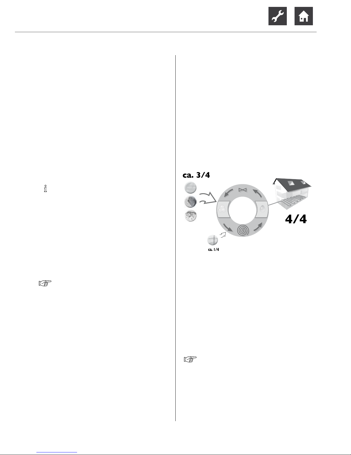
Heat pumps operate on the same principle as a
refrigerator: same technology, only with reversed
benets. The refrigerator extracts heat from foods,
which is released into the room through ns on the back.
The heat pump extracts heat from our environment:
air, earth or ground water. The extracted heat is
conditioned in the unit and supplied to the heating water.
Even when it is extremely cold outside, the heat pump
draws enough heat to heat a house.
Example: drawing of a brine/water heat pump with oor
heating:
4/4 = usable energy
approx. 3/4 = environmental energy
approx. 1⁄4 = external electrical
energy
Area of utilisation
Taking into consideration the ambient conditions, limits
of application and the applicable regulations, every heat
pump can be utilised in new or existing heating systems.
Overview “Technical data / scope of delivery”.
Page 6

6
Subject to change without notice | 83053700gUK – Translation into English of the original German operating manual | ait-deutschland GmbH
Heat metering
In addition to proof of the unit’s efciency, the
EEWaermeG also requires heat metering (hereafter
referred to as HQR). Heat metering is mandatory for
air/water heat pumps. Heat metering for brine/water
and water/water heat pumps only have to be installed
for a ow temperature ≥ 35 °C. The heat metering must
record the total thermal energy released (heating and
domestic hot water) in the building. In heat pumps with
heat metering, the analysis is carried out by the regulator.
The regulator displays the thermal energy discharged in
the heating system in kWh.
Operation
Your decision to purchase a heat pump or a heat
pump system is a long-term contribution to protecting
the environment through low emissions and reduced
primary energy use.
To ensure that your heat pump or heat pump system
operates efciently and ecologically, the following are
especially important:
€
ENERGY SAVING TIP
Avoid unnecessarily high ow temperatures.
A lower ow temperature on the hot water side
increases the efciency of the system.
€
ENERGY SAVING TIP
Preferably use purge ventilation. Compared to
continuously open windows, it is better to air
rooms by fully opening windows for a short
period, two to three times a day (so-called
“rapid” or “purge” ventilation); this reduces
energy consumption and your heating bill.
You can operate and control the heat pump system
with the control element of the heating and heat pump
regul at o r.
NOTE.
Make sure that the control settings are correct.
Operating manual of the heating and heat pump
regul at o r.
Cooling
There are two ways to use the heat pump for air conditioning in rooms, through: „passive cooling“ and „active
cooling“.
The main difference is the compressor operation. While the compressor is not needed for passive cooling, i.e.
it is passive, the compressor operates during active cooling, i.e. it is active.
Another difference is that both passive and active cooling is possible with the ground and groundwater heat
sources. But only active cooling is possible with the outside air heat source.
Passive cooling is the more cost-effective option. Lowering the temperature by 3-4 K is often fully sufcient to
produce a comfortable room temperature in the summer.
Whereas higher cooling output is possible with active
cooling.
Passive cooling uses the fact that the ground and groundwater, from a depth of around 8 metres, are more or
less a constant temperature all year round and in the
summer are around 9 °C to 10 °C cooler than the outside air or the interior rooms.
This temperature difference is sufcient to cool a building with energy from the ground and groundwater. Additional fan coils, cooling ceilings, underoor heating and
thermo active building systems (embedding cooling pipes), such as concrete core thermal activation, can be
used for direct cooling.
ATT E NTIO N
By cooling with low ow temperatures, conden-
sate can be expected to form on the heat distribution system as the temperature falls below the
dew point. If the heat distribution system is not
designed for these operating conditions, it must
be protected by appropriate safety devices, e.g.
dew point monitor (purchasable accessory).
NOTICE
If the heating surfaces are used for heating and
cooling, the control valves must be suitable for
heating and cooling.
In addition, a dew-point monitor should be used
for cooling.
NOTE
Use recommended accessory dew point moni-
tors.
Page 7
7
Subject to change without notice | 83053700gUK – Translation into English of the original German operating manual | ait-deutschland GmbH
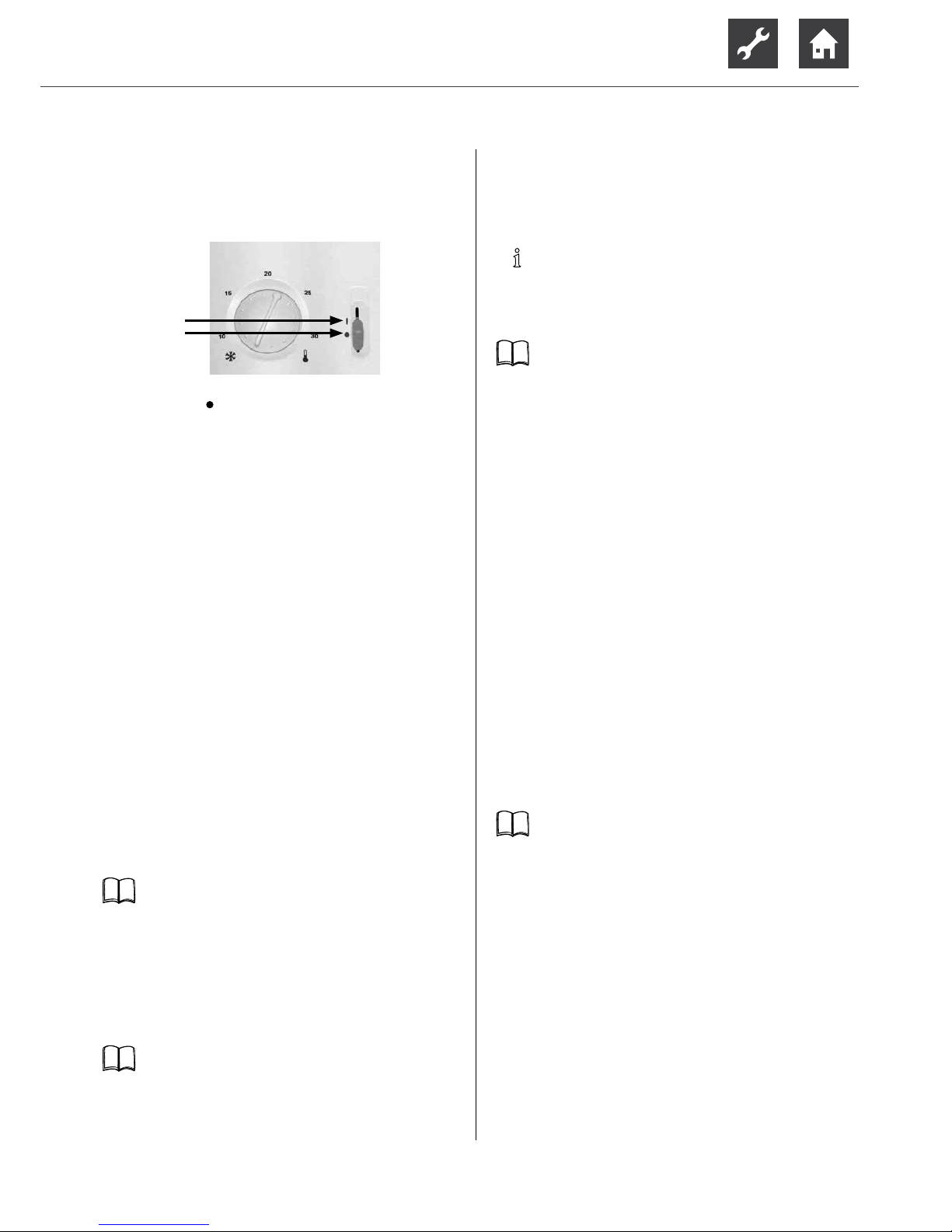
THE ROOM THERMOSTAT OF THE COOLING FUNCTION
(PURCHASABLE ACCESSORIES, OPTIONAL)
The room thermostat is used to release and to switch
off the cooling function:
I Cooling function switched on
Cooling function off
USE OF THE COOLING FUNCTION
The heating and heat pump regulation program activates
the cooling function only if the following conditions are
fullled:
•
Heat pump type with integrated cooling function.
•
Room thermostat of the cooling function is swit-
ched on.
•
Temperature of the heat source is ≥ +5 °C.
•
Heat pump is currently not being used for „heating“
nor for „domestic water heating“.If the heat pump
control program sends the “domestic water heating” request to the heat pump, the cooling function
of the heat pump stops automatically for the duration of the domestic water heating.
•
The „Automatic“ setting is selected under the
„Cooling mode“ heading.
•
The outside temperature release set at the control
is exceeded.
Operating manual of the heating and heat pump
regul at o r.
The cooling function can be used in two variants:
Var iant 1:
Manual switching from heating to cooling mode
(and vice versa). This uses a xed pre-set ow
temperature.
Operating manual of the heating and heat pump
cont ro l l e r.
Variant 2:
Automatic switching from heating to cooling
mode (and vice versa). This variant can operate
using a cooling curve.
NOTE
Variant 2 is only possible if the expansion board
(purchasable accessories) is installed in the heating and heat pump controller.
Expansion board operating manual
Care of the unit
The outer surfaces of the unit can be cleaned with a
damp cloth and standard cleaning products.
Do not use cleaning or care products that contain
abrasives, acids and/or chlorine. Such products would
destroy the surfaces and could also damage the technical
components of the unit.
Maintenance of the unit
The cooling circuit of the heat pump requires no regular maintenance.
According to EU regulation (EC) 517/2014, leak
inspections and maintenance of a log book are required
by law for certain heat pumps!
Log book for heat pumps, Section “Information
on use of the log book”.
The components of the heating circuit and the heat
source (valves, expansion vessels, circulating pumps,
lters, dirt traps) should be inspected and cleaned
as needed - at the very least annually - by qualied
personnel (heating or cooling system tters).
It is best to arrange a maintenance agreement with a
heating installation company. The company will arrange
for the required maintenance at regular intervals.
Page 8
8
Subject to change without notice | 83053700gUK – Translation into English of the original German operating manual | ait-deutschland GmbH
CLEANING AND FLUSHING OF UNIT COMPONENTS
CAUTION!
Unit components may be cleaned
and ushed only by customer service
personnel authorised by the manufacturer.
Use only liquids recommended by the
manufacturer.
Flushing of the liqueer with chemical
cleaning agents must be followed by
neutralisation of residue and intensive
ushing with water. Always observe the
technical data of the manufacturer of the
heat exchanger.
Malfunctions
In the event of a fault, you can read out the cause of the
fault from the diagnostic program of the heating and heat
pump regulator.
Operating manual of the heating and heat pump
regul at o r.
WARNING!
Only customer service personnel
authorised by the manufacturer may
carry out service and repair work on the
components of the unit.
Scope of delivery
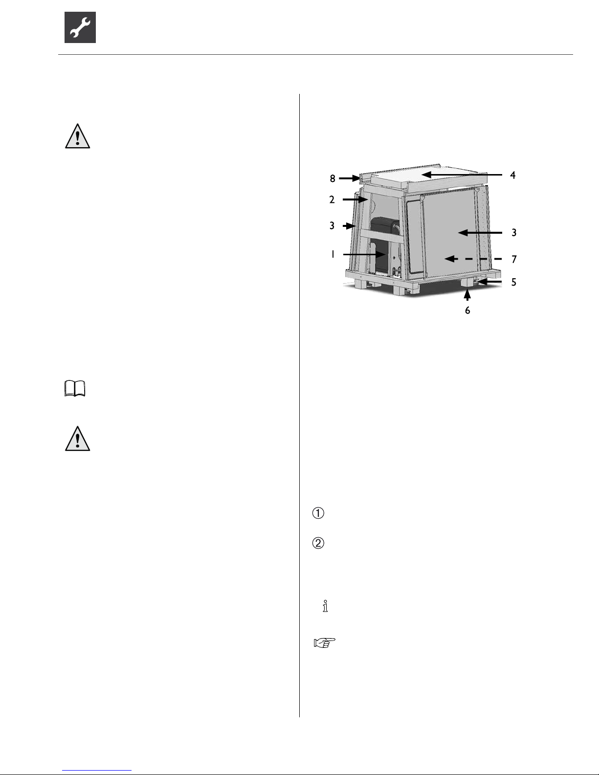
Example of scope of delivery:
Size 1:
As delivered:
1 Heat pump = complete indoor unit
2 Transport frame
3 Facing panels placed to
the side (5 panels)
4 Insulation panel, which is then
pushed under the baseplate
(sound insulation)
5 Pre-tted adjustable feet (4)
6 Spacer blocks (4), which can be
unscrewed after installation
7 Extra box with accessories (indoors)
8 Prole rails
Complete the following rst:
Check the delivery for outwardly visible signs of
damage…
Check that nothing is missing from the scope of
supply…
Any defects or incorrect deliveries must be
reported immediately.
NOTE.
Note the unit model.
Overview “Technical data / scope of delivery”.
Page 9
9
Subject to change without notice | 83053700gUK – Translation into English of the original German operating manual | ait-deutschland GmbH
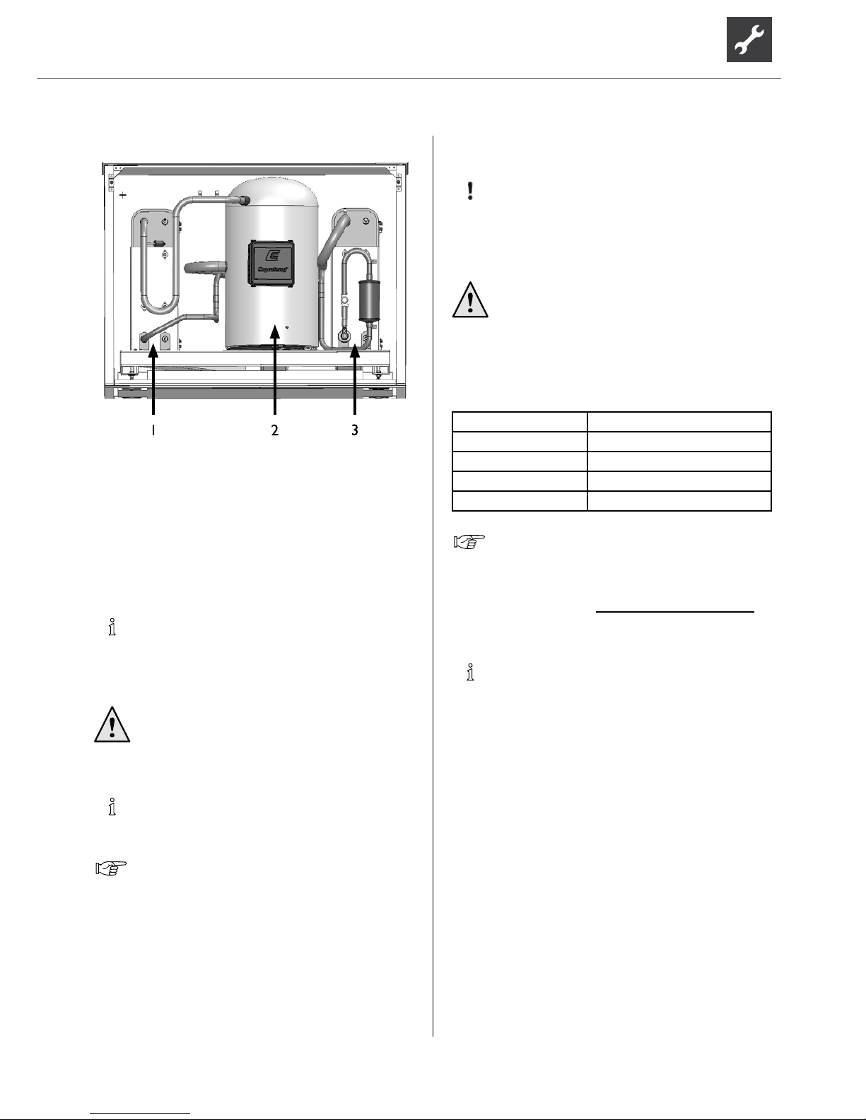
MAIN COMPONENTS
1 condenser
2 compressor
3 evaporator
Installation
Observe the following when performing all work:
NOTE.
Always comply with the applicable local accident
prevention regulations, statutory regulations,
ordinances, guidelines and directives.
WARNING!
The heat pump or heat pump system
may only be installed and assembled by
qualied personnel!
NOTE.
Observe the sound levels of the respective
model.
Overview “Technical data / scope of delivery”,
“Sound” section.
INSTALLATION AREA
ATT E NTIO N .
Install the heat pump only indoors.
The installation room must be frost-free and
dr y.
WARNING!
Please note and follow the respective
relevant local standards, directives and
regulations applicable, especially the
minimum volume necessary depending
on the refrigerant capacity of the relevant
heat pump system (EN 378-1).
Refrigerant Limit
R 13 4 a 0.25 kg/m³
R 404A 0.48 kg/m³
R 407C 0.31 kg/m³
R 410A 0.44 kg/m³
Overview “Technical data / scope of delivery”,
“General unit data” section.
Minimum volume =
Refrigerant capacity [kg]
Limit [kg/m³]
NOTE.
If several heat pumps of the same type
are installed, only one heat pump must be
considered.
If several heat pumps of different types are
installed, the heat pump with the largest
refrigerant capacity must be considered.
Page 10
10
Subject to change without notice | 83053700gUK – Translation into English of the original German operating manual | ait-deutschland GmbH
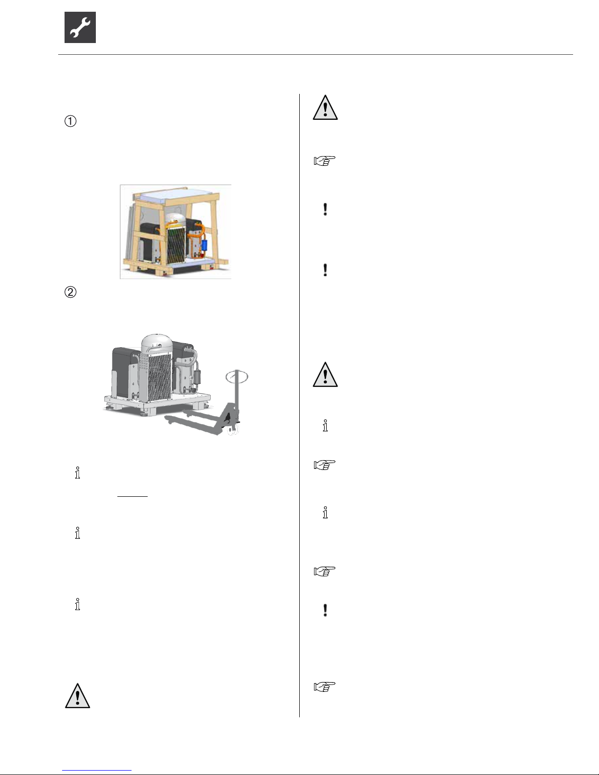
TRANSPORT TO INSTALLATION LOCATION
Before transporting the heat pump to the nal
installation location the packaging and wooden
frame can be dismantled.
To do this, remove the facing panels on the long
sides, undo the wooden boards and remove the two
machine screws (M8) in each of the sides.
You can now lift the unit with the help of a pallet
truck or fork lift truck and transport it to its nal
installation location.
NOTE.
The unit has ground clearance for easy access
from all sides
NOTE.
The baseplate is 76 cm wide, so that the heat
pump can be transported through a standard
door opening.
NOTE.
Keep the components enclosed in the scope of
delivery in a safe place until the assembly.
Always comply with the following safety information
during transport:
CAUTION!
Wear safety gloves.
WARNING!
Several people are required to transport
the unit. Do not underestimate the weight
of the unit.
Overview “Technical data / scope of delivery”,
“General unit data” section.
ATT E NTIO N .
Never use components and hydraulic
connections on the unit for purposes of
transport.
ATT E NTIO N .
Do not tilt the unit more than a maximum of 45°
(in any direction).
INSTALLATION
WARNING!
Several people are required to install the
unit.
NOTE.
Take into account the size of the unit.
Overview “Technical data / scope of delivery”,
“General unit data” section.
NOTE.
Always follow the installation plan for the
respective model. Note the size and minimum
clearances.
Installation plan for respective model.
ATT E NTIO N .
The heat pump must be installed on a rm,
horizontal surface. Make sure that the foundation
is designed for the weight of the heat pump.
Do not use a rigid foam boiler pedestal!
Overview “Technical data/scope of delivery”,
“General unit data” section.
Page 11
11
Subject to change without notice | 83053700gUK – Translation into English of the original German operating manual | ait-deutschland GmbH
NOTE.
Set up the unit so that the operating side is
accessible at all times!
ATT E NTIO N .
Do not tilt the unit more than a maximum of 45°
(in any direction).
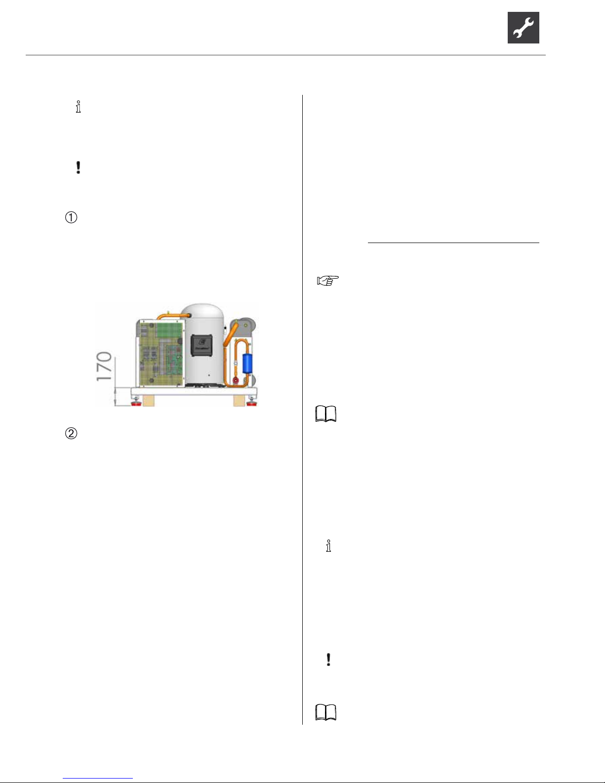
Lower the basic heat pump module on the 4 wooden
transport blocks in its nal installation location.
Now use the vibration-decoupling, adjustable
machine feet to align the unit horizontally. Ensure
the distance from the nished oor level to the top
of the heat pump baseplate is 170mm. Lock this
setting by locking the nuts.
The four transport blocks (each with 2 universal
wood screws) must then be removed.
Installation of the hydraulic
connections
BUFFER TANK
The hydraulic connection of the heat pump requires a
buffer tank in the heating circuit. The required volume
of the buffer tank is calculated based on the following
formula:
V
Buff er tank
=
minimum ow rate of heat circuit volume ow / hour
10
For the minimum ow rate of the heat circuit
volume ow, see overview “Technical data/
Scope of delivery”, “Heating circuit” section.
DOMESTIC WATER HEATING
The domestic water heating with the heat pump requires
an additional hot water circuit, parallel to the heating
circuit. When installing, make sure that the domestic hot
water charge is not fed through the buffer tank of the
heating circuit.
“Hydraulic connection” instructions.
DOMESTIC HOT WATER TANK
If the heat pump is to be used for domestic water
heating, you must integrate special domestic hot water
tanks in the heat pump system. Choose a storage volume
so that the required quantity of hot water is available
even during a power cut.
NOTE:
The heat exchanger surface of the domestic hot
water tank must be dimensioned so that the
heating capacity of the heat pump is transferred
with minimum spread.
We offer a variety of domestic hot water tanks for you
to choose from. They are optimised for use with your
heat pump.
ATT E NTIO N .
Connect the unit to the heating circuit according
to the hydraulic diagram for the respective
model.
“Hydraulic connection” instructions.
Page 12
12
Subject to change without notice | 83053700gUK – Translation into English of the original German operating manual | ait-deutschland GmbH
ATT E NTIO N .
The heat source system must be designed
according to the specications of the planning
manual.
Planning manual and “Hydraulic connection”
documents.
NOTE:
Check to make sure that the diameters and
lengths of the pipes for the heating circuit and
the heat source are sufciently dimensioned.
NOTE:
Circulating pumps, which pump the volume ow
through the heat pump, must be designed as
multi-stage pumps. They must at least provide
the minimum throughput rate required for your
model.
In the case of heat source pumps, the viscosity of
the brine liquid must also be taken into account!
Overview “Technical data / scope of delivery”,
“Heat circuit” and “Heat source” sections.
ATT E NTIO N .
The hydraulic system must be equipped with
a buffer tank, the required volume of which
depends on the model of your unit.
ATT E NTIO N .
When installing the connections, always secure
the connections on the unit against twisting, in
order to prevent damage to the components
inside the unit.
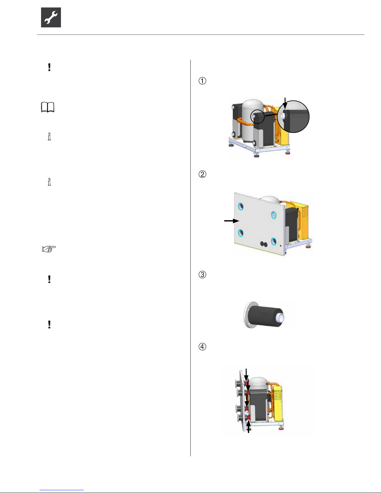
The following steps are to be carried out on all 4
hydraulic connections of the heat pump:
Push the insulation elements included in the scope
of delivery onto the plate heat exchanger
Position the back panel of the heat pump on the
basic heat pump module
Connect the piece of pipe supplied to the threaded
ange and insulate it with the enclosed insulating
hose
Connect the connectors to the connection clip
included in the scope of supply to the corresponding
connection on the heat pump.
Page 13
13
Subject to change without notice | 83053700gUK – Translation into English of the original German operating manual | ait-deutschland GmbH
Use the insulating tape supplied to insulate the
connection clip. Use the enclosed fastening
materials to additionally x the insulation.
NOTE:
We recommend completing step after the
leak test.
NOTE:
The heat source and heating side must be
insulated from the heat pump; to this end we
recommend using the IPFK hydraulic connection
set in our range of products (not included in the
scope of delivery).
Install shut-off devices at the heating circuit.
Install shut-off devices at the heat source.
Place a bleeder at the highest point of the heat
source in the heat source outlet…
We recommend installing a dirt lter (screen size
0.9 mm) on the heat source inlet connection…
The hot water and heat source connections are
marked accordingly on the unit.
For the positioning of the connections, please
refer to the dimensioned drawing for the
respective model.
INSTALLING THE HOUSING
NOTE.
Remove the protective lm from all facing panels.
NOTE.
The screws for installing the heat pump housing
are included in the scope of delivery.
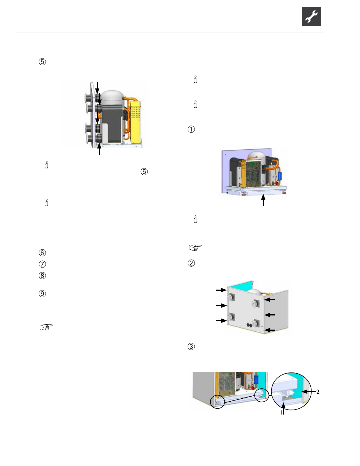
Position the insulation included in the scope of
delivery under the baseplate.
NOTE.
Before screwing on the side panels, feed the patch
cable and + LIN bus cable through the rear panel!
see “electrical connection work”
Screw the two side panels onto the back panel using
3 screws for each:
Mount the prole rail onto the front of the unit,
between the two side panels, using 2 screws for
each side.
1 Prole rail
2 Screw
Page 14
14
Subject to change without notice | 83053700gUK – Translation into English of the original German operating manual | ait-deutschland GmbH
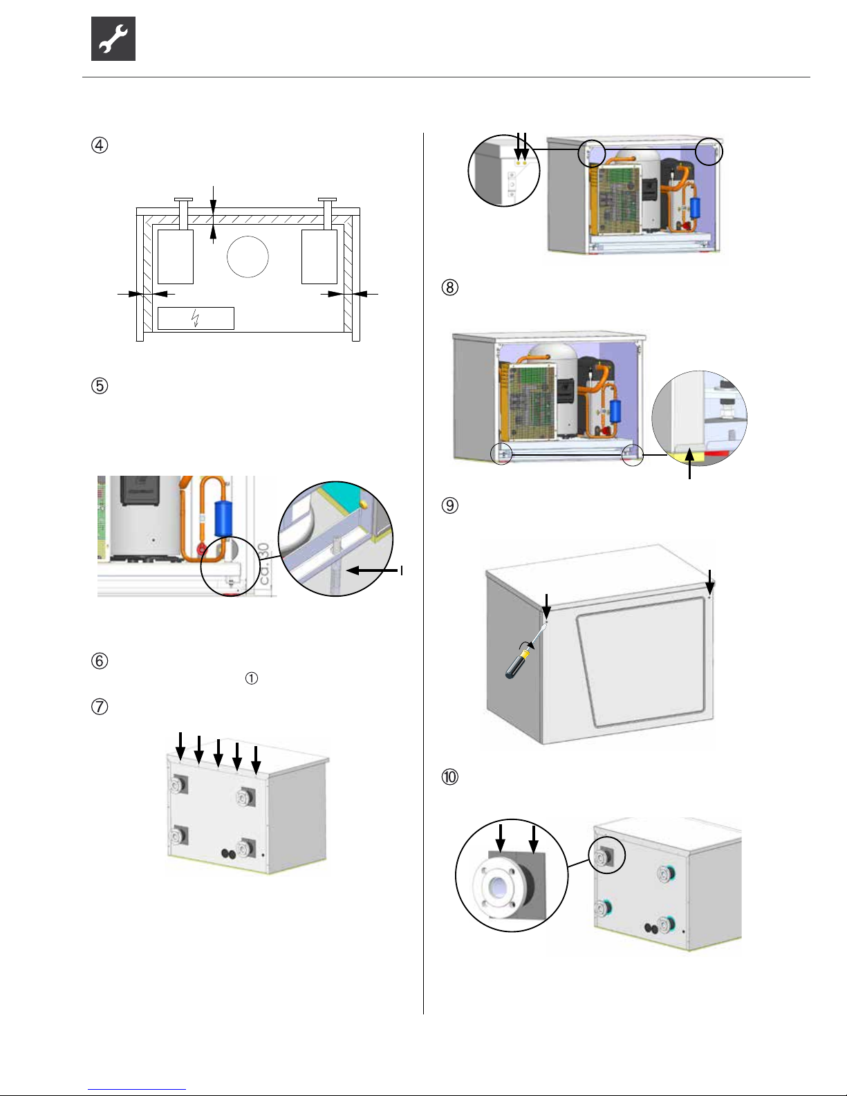
Align the facing with the baseplate as shown in the
following sketch
28
28
28
Secure and x the facing on the prole rail using the
fastening materials included in the scope of delivery
(2 x 10mm anchors and 2 x M8 hanger bolts). Twist
the hanger bolt into the oor up to the start of the
thread.
1 hanger bolt with anchor
Align the insulating board under the unit with the
middle of the unit (see
).
Fix the housing cover onto the rear panel (5 screws):
and the two side panels (2 screws each) onto the
front:
The front panel can now be hung into the clips
provided at the bottom
and locked by means of the two quarter-turn
screws.
Glue the insulating half-shells included in the scope
of delivery around the pipe pieces in the rear panel.
Page 15
15
Subject to change without notice | 83053700gUK – Translation into English of the original German operating manual | ait-deutschland GmbH
Electrical connections
The following applies to all work to be done:
DANGER!
Risk of fatal injury due to electric shock!
All electrical connections must be carried
out by qualied electricians only.
Before opening the unit, disconnect the
system from the power supply and prevent
it from being switched back on!
WARNING!
During installation and while carrying out
electrical work, comply with the relevant
EN-, VDE and/or local safety regulations.
Comply with technical connection
requirements of the responsible power
supply company (if required by the latter)!
NOTE.
All cables must be fed through the openings in
the back panel!
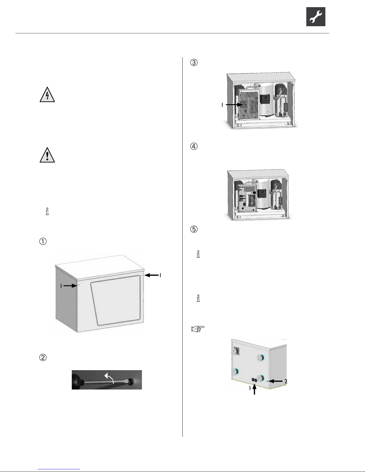
The front panel is hung in at the bottom and is held
in place at the top by 2 quarter-turn screws.
1 Quarter-turn screws
Open the quarter-turn screws of the front panel by
turning them through 90° anticlockwise…
Lift out front panel and set aside in a safe place…
1 Electrical switch cabinet
Open the unit’s electrical switch cabinet:
Undo the 6 screws slightly, in order to unhook the
cover panel by lifting it slightly…
Several openings are provided at the back of the
unit for passing through the cables:
NOTE.
When laying the cable, ensure that unshielded
power supply cables and shielded cables (LIN
bus) are laid separately from each other.
NOTE.
LIN bus length may not be increased. However,
they can be shortened.
For further details, see “installation plan”
1 Electric cable penetration
2 Penetration, LIN bus and patch
cable for Luxtronik 2.0 regulator
Page 16
16
Subject to change without notice | 83053700gUK – Translation into English of the original German operating manual | ait-deutschland GmbH
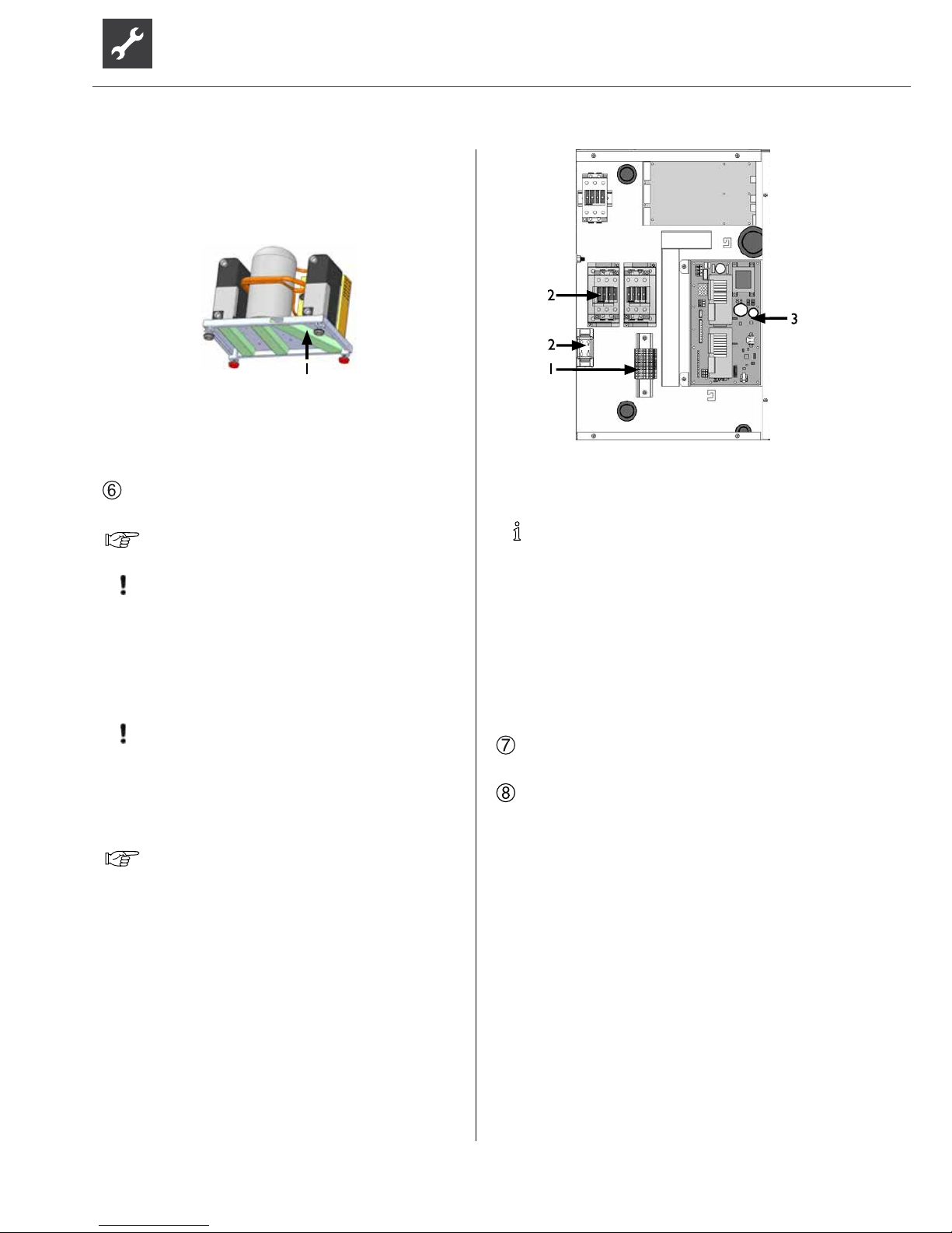
The external electric cables to be provided must be fed
through the grommets cut out in the bottom of the rear
panel and then fed into the electrical switch cabinet by
means of the cable duct, which is integrated into the
baseplate of the heat pump.
1 Cable duct
The cables laid in the switch cabinet for the regulator
(patch cable, LIN bus) must be fed through the grommet
cut out in the bottom of the rear panel.
Make electrical connections according to the
terminal diagram…
“Terminal diagrams” for respective model.
ATT E NTIO N .
Ensure clockwise rotary eld of the load power
supply (compressor).
Operation with the incorrect rotary direction of
the compressor can cause serious, irreparable
damage to the compressor.
ATT E NTIO N .
The power supply for the heat pump must be
equipped with an all-pole automatic circuitbreaker with at least 3mm contact spacing to
IEC 60947-2.
Note the level of the tripping current.
Overview “Technical data / scope of delivery”,
“Electrics” section.
1 Control voltage connection
2 Compressor output connection
3 Regulator board
NOTE.
The control element of the heat and heat pump
regulator can be connected to a computer or
network using a suitable network cable, enabling
the heating and heat pump regulator to be
controlled remotely from there.
If such a connection is required, lay a shielded
network cable (category 6, with RJ-45
connector) up to the control element while
carrying out the electrical connection work.
After completion of all electrical installation work,
close the switch cabinet inside the unit.
Screw on the front panel of the unit if no further
installation work inside the unit is to be performed
immediately.
Page 17
17
Subject to change without notice | 83053700gUK – Translation into English of the original German operating manual | ait-deutschland GmbH
Installation of the control
element
NOTE.
Note the distance between the control element
and the unit.
For further details, see “installation plan”
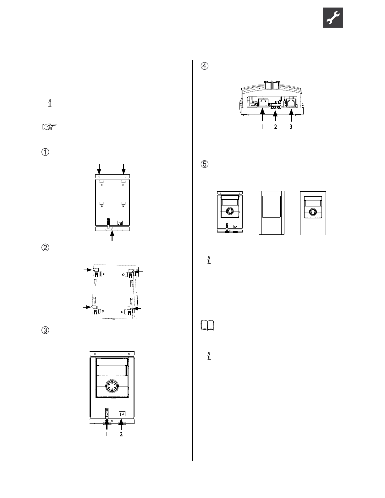
Control element for wall-mounting
Fasten the wall bracket using the assembly materials
included in the scope of delivery.
There are 4 xing hooks on the back of the control
element.
Hang the control element on the wall bracket using
the 4 xing hooks and push down until it latches
into position.
1 Shielded terminal
for LIN bus cable/strain relief
2 Strain relief
Connection of patch cable and LIN bus cable to the
regulator (via the strain relief):
1 Patch cable to the network link
2 LIN bus to the regulator board in the unit
3 Patch cable to the regulator
board in the unit
If the work on the heat pump regulator has been
completed, the cover can be clipped onto the wall
bracket.
+
=
NOTE.
A connection to a computer or a network can
be installed via the left bushing on the bottom
of the control element, thus allowing the heating
and heat pump regulator to be controlled
remotely. This requires that a shielded network
cable was laid up to the heat pump regulator
during the electrical connection work.
Operating manual for the heating and heat pump
regulator, version “Qualied heating engineers”,
“Web server” section.
NOTE.
The network cable can be exchanged at any
time. In order to be able to connect it, the
screen must rst be removed.
Page 18
18
Subject to change without notice | 83053700gUK – Translation into English of the original German operating manual | ait-deutschland GmbH
Flushing and lling the unit
CAUTION.
The system must be absolutely free from air
before commissioning.
FLUSHING AND FILLING THE HEAT SOURCE
Contamination and deposits in the heat source can cause
malfunctions.
ATT E NTIO N .
Before ushing and lling the heat source the
drain pipe of the safety valve must be connected
- Important: do not discharge into the drains
(anti-freeze mixture)!.
NOTE
The following antifreezes are approved for the
brine circuit:
•
Monopropylene glycol
•
Monoethylene glycol
•
Ethanol
•
Methanol
ATT E NTIO N
Ensure that the (pipe) materials, seals and other
components used on site are made of materials
that are compatible with the antifreeze used!
WARNING!
Methanol and ethanol can evaporate, gi-
ving off ammable and explosive gases.
Therefore, the relevant antifreeze safety
regulations must be noted and followed!
Flush heat source system thoroughly.
Thoroughly mix the anti-freeze, available as an
accessory, with water with the required ratio.
Add only anti-freeze mixed with water to the heat
source.
ATT E NTIO N .
The concentration of anti-freeze in the water
must be at the level specied for your model.
Overview “Technical data / scope of delivery”,
“Heat source” section.
Check the concentration of the anti-freeze in the
mixture…
Fill heat source with the anti-freeze mixture…
Bleed the heat source.
FLUSHING AND FILLING THE HEATING CIRCUIT
WATER QUALITY
OF THE FILL AND ADDITIONAL WATER IN HOT WATER
HEATING SYSTEMS ACCORDING TO VDI 2035 PART I
AND II
Use of modern, energy-efcient heat pump systems
is becoming increasingly widespread. Their ingenious
technology enables these systems to achieve very good
efciencies. The decreasing space available for heat
generators has led to the development of compact
units with increasingly smaller cross-sections and high
capacities. This means the complexity of the systems and
the material diversity are also increasing, which plays an
important role especially in their corrosion behaviour.
The heating water not only affects the efciency of the
system, but also the life of the heat generator and the
heating components of a system.
The guide values of VDI 2035 Part I and Part II must
therefore be complied with as minimum requirements
for proper operation of the systems. Our practical
experience has shown that the safest and most troublefree running of the systems is achieved with so-called
low-salt operation.
VDI 2035 Part I gives important information and
recommendations regarding scaling and its prevention in
heating and domestic hot water heating systems.
VDI 2035 Part II primarily deals with the requirements
for reducing heating water corrosion in hot water
heating systems.
PRINCIPLES OF PART I AND PART II
The occurrence of scaling and corrosion damage in hot
water heating systems is low, if
- proper planning and commissioning is carried out
- the system is closed in corrosion terms
- adequately dimensioned pressurising is integrated
- the guide values for the heating water are complied
with
Page 19

19
Subject to change without notice | 83053700gUK – Translation into English of the original German operating manual | ait-deutschland GmbH
- and regular servicing and maintenance are carried out.
A system log should be kept, in which the relevant
planning data is entered (VDI 2035).
DAMAGE THAT CAN OCCUR IN CASE OF NON-
COMPLIANCE
- Malfunctions and the failure of components (e.g. pumps,
valves)
- Internal and external leaks (e.g. from heat exchangers)
- Cross-section reduction and blockaging of components
(e.g. heat exchanger, pipes, pumps)
- Material fatigue
- Gas bubbles and gas cushion formation (cavitation)
- Negative effect on heat transfer (formation of coatings,
deposits) and associated noises (e.g. boiling noises,
ow noises)
LIMESCALE – THE ENERGY KILLER
Filling with untreated drinking water inevitably leads to
the precipitation of all calcium as scale. The consequence:
limescale deposits form on the heat transfer surfaces of
the heating. The efciency falls and the energy costs rise.
A rule of thumb is that 1 millimetre of limescale deposit
causes an energy loss of 10%. In extreme cases it can
even cause damage to the heat exchangers.
WATER SOFTENING TO VDI 2035 – PART I
If the water is softened before the heating is lled, in
accordance with the VDI 2035 guidelines, no scale
can form. This effectively and permanently prevents
limescale deposits and the resulting negative effects on
the entire heating system.
CORROSION – AN UNDERESTIMATED PROBLEM
VDI 2035, Part II, deals with the problem of corrosion.
Softening the heating water can prove to be insufcient.
The pH value can signicantly exceed the limit of 10.
pH values higher than 11 can set in, which even damage
rubber seals. The VDI 2035, Part 1 guidelines are
fullled, however, VDI 2035, Part 2 suggests a pH value
between 8.2 and maximum 10.
If aluminium materials are used, which is the case in
many modern heating systems, a pH value of 8.5 must
not be exceeded, because otherwise there is a threat
of corrosion – and aluminium is attacked without the
presence of oxygen. Therefore, apart from softening
the heating ll and additional water, the heating water
should also be appropriately conditioned. This is the
only way to comply with the VDI 2035 requirements and
the recommendations and installation instructions of the
heat pump manufacturer.
Part 2 of VDI 2035 also points out the reduction in total
salt content (conductivity). The risk of corrosion is far
lower if deionised water is used than is the case if the
system is operated with salty, i.e. softened water.
Even if the water has been softened beforehand, it
contains dissolved, corrosion-promoting salts, which act
as electrolytes due to the use of different materials in
the heating system and therefore accelerate corrosion
processes. This can ultimately result in pitting.
ON THE SAFE SIDE WITH LOW-SALT OPERATION
The problems listed above do not occur at all with
low-salt operation, as neither corrosive salts such as
sulphates, chlorides and nitrates nor alkalising sodium
hydrogen carbonate are in the heating water. The
corrosive properties of deionised water are very low
and in addition, fur cannot form in the boiler. This is the
ideal approach for closed heating circuits, in particular,
because low oxygen input into the heating circuit can
also be tolerated.
In general, when the system is lled with deionised
water, the pH value sets itself within the ideal range due
to „self-alkalinisation“. If necessary, a pH value of 8.2
can be very easily alkalised by adding chemicals. In this
way, optimum protection of the entire heating system is
achieved.
MONITORING
Analytical recording and monitoring of the relevant
water values and the added active conditioning
substances is of decisive importance. Therefore, they
should be monitored regularly using appropriate water
test equipment.
ATT E NTIO N .
Before ushing and lling the heating circuit, the
drain pipe of the safety valve must be connected.
Flush heating circuit system thoroughly.
Fill heating circuit…
Bleed heating circuit.
Page 20

20
Subject to change without notice | 83053700gUK – Translation into English of the original German operating manual | ait-deutschland GmbH
Insulating the hydraulic
connections
NOTE.
Insulate the heating circuit and the heat source
according to relevant local standards and
guidelines.
Check all hydraulic connections for leaks. Perform
leak test…
Insulate all connections, vibration isolation,
connections and pipes of the heating circuit and the
heat source. Insulate the heat source so that it is
vapour-diffusion tight.
Commissioning
NOTE.
The commissioning has to be in the heating
mode.
Carry out a thorough installation check and work
through the general checklist…
Manufacturer’s homepage.
By checking the installation you prevent damage to
the heat pump system, which could be caused by
work carried out improperly.
Check that…
•
clockwise rotary eld of the load power supply
(compressor) is ensured.
•
The heat pump installation and assembly have
been carried out according to the requirements
of this operating manual.
•
the electrical installation work has been
completed properly.
•
The power supply for the heat pump must be
equipped with an all-pole automatic circuitbreaker with at least 3 mm contact spacing to IEC
60947-2.
•
The heating circuit is ushed, lled and thoroughly
vented.
•
All valves and shut-off devices of the heating
circuit are open.
•
All pipe systems and components of the system
are leaktight.
Carefully ll out and sign the completion report for
heat pump systems...
Manufacturer’s homepage.
Within Germany and Austria:
Send completion report for heat pump systems
and general checklist to the manufacturer’s factory
customer service department…
In other countries:
Send completion report for heat pump systems
and general checklist to the manufacturer’s local
pa r t n e r…
The heat pump system is commissioned by customer
service personnel authorised by the manufacturer.
There is a fee for starting up!
Page 21
21
Subject to change without notice | 83053700gUK – Translation into English of the original German operating manual | ait-deutschland GmbH
Dismantling
DANGER!
Risk of fatal injury due to electric shock!
Electrical connections may be installed
only by qualied electricians.
Before opening the unit, disconnect the
system from the power supply and prevent
it from being switched back on!
WARNING!
Only qualied heating or cooling system
personnel are allowed to remove the unit
from the system and dismantle the unit.
ATT E NTIO N .
The anti-freeze mixture of the heat source must
not be allowed to enter the sewer system.
Collect anti-freeze mixture and dispose of
properly.
ATT E NTIO N .
Recycle or ensure proper disposal of unit
components, refrigerants and oil according
to the relevant regulations, standards and
guidelines.
REMOVAL OF THE BUFFER BATTERY
ATT E NTIO N .
Before scrapping the heating and heat pump
regulator, remove the buffer battery on the
processor board. The battery can be pushed
out using a screwdriver. Dispose of battery and
electronic components in an environmentally
friendly way.
Page 22

22
Subject to change without notice | 83053700gUK – Translation into English of the original German operating manual | ait-deutschland GmbH
Device designation
Heat pump type Brine/Water ı Air/Water ı Water/Water • relevant ı — not relevant
Installation location Indoors ı Outdoors • relevant ı — not relevant
Conformity CE
Power data Heating power/COP at
B0/W35 Standard point as per EN14511
2 Compressors
1 Compressor
kW ı …
kW ı …
B0/W45 Standard point as per EN14511
2 Compressors
1 Compressor
kW ı …
kW ı …
B7/W35 Standard point as per EN14511
2 Compressors
1 Compressor
kW ı …
kW ı …
B0/W50 Standard point as per EN14511
2 Compressors
1 Compressor
kW ı …
kW ı …
Operating limits Heat circuit °C
Heat source °C
Additional operating points …
Noise Sound pressure level at 1m gap around the machine averaged (in free field) dB(A)
Sound power level as per EN12102 dB
Heat source Volumetric flow: minimum throughput ı nominal throughput ı maximum throughput l/h
Pressure loss in heat pump ∆p ı Volumetric flow bar ı l/h
Recommended brine circulating pump …
Total compression of the recommended pump at nominal brine volumetric flow bar ı l/h
Antifreeze Monoethylene glycol
Minimum concentration ı frostproof to % ı °C
Heat circuit Volumetric flow: minimum throughput ı nominal throughput ı maximum throughput l/h
Pressure loss in heat pump ∆p ı Volumetric flow bar ı l/h
Free compression of heat pump ∆p ı Volumetric flow bar ı l/h
Temperature spread for B0/ W35 K
General device data Earth (see dimensional diagram for the size indicated) Size
Total weight kg
Extra weight of construction unit 1 kg
Extra weight of construction unit 2 kg
Connections Heat circuit …
Heat source …
Refrigerant Refrigerant type ı Filling capacity … ı kg
Electrics Voltage code ı All-pole circuit breaker for pump *) … ı A
Voltage code ı Control voltage circuit breaker *) … ı A
Voltage code ı Electrical heating element circuit breaker *) ı A
Heat pump Effect. power consumption in the normal point B0/W35 as per EN14511: Power c onsumption ı Current consumption ı cosφ kW ı A ı …
Maximum machine current within the operating limits A
Starting current: direct ı with slow-starter A ı A
Protection type IP
Power of electrical heating element 3 ı 2 ı 1-phase kW ı kW ı kW
Components Circulating pump for heat circuit at nominal throughput: Power consumption ı Current consumption kW ı A
Circulating pump for heat source at nominal throughput: Power consumption ı Current consumption kW ı A
Setting range for motor protection switch of heat source circulating pump A
Passive cooling function Data only for devices with ID K: Cooling power at nominal volumetric flow rates (15 °C heat source, 25 °C hot water) kW
Safety devices Safety assembly for heat circuit ı Safety assembly for heat source in scope of supply: • yes — no
Heating and heat pump control in scope of supply: • yes — no
Electronic soft-starter integrated: • yes — no
Expansion vessels Heat source: Scope of supply ı Volume ı Supply pressure • yes — no ı l ı bar
Heat circuit: Scope of supply ı Volume ı Supply pressure • yes — no ı l ı bar
Overflow valve integrated: • yes — no
Vibration isolation Heat circuit ı Heat source in scope of supply: • yes — no
UK81319 8a
*) Observe local regulations n.n. = cannot be demonstrated
Technical data / scope of delivery
Page 23

23
Subject to change without notice | 83053700gUK – Translation into English of the original German operating manual | ait-deutschland GmbH
SWP561H
• ı — ı —
• ı —
•
-
53,8 ı 4,50
-
52,9 ı 3,80
-
65,9 ı 5,20
-
52,1 ı 3,10
20 - 64
-5 - 25
B0/W70
44
59
9400 ı 12600 ı 19100
0,16 ı 12600
—
—
•
25 ı -13
4400 ı 8900 ı 11200
0,12 ı 8900
— ı —
5,0
1
521
—
—
DN50 DIN2566
DN50 DIN2566
R134a ı 12,8
3~/PE/400V/50Hz ı C50
1~/N/PE/230V/50Hz ı B16
— ı —
12,0 ı 27,80 ı 0,63
45,6
310 ı 105
20
— ı — ı —
— ı —
— ı —
—
—
— ı —
•
•
— ı —
— ı —
—
—
8134 33a
SWP691
• ı — ı —
• ı —
•
-
68,5 ı 4,60
-
66,1 ı 3,60
-
84,1 ı 5,40
-
64,6 ı 2,90
20 - 60
-5 - 25
B0/W65
44
59
13000 ı 17300 ı 21000
0,16 ı 17300
—
—
•
25 ı -13
5700 ı 11300 ı 14200
0,12 ı 11300
— ı —
5,2
1
484
—
—
DN50 DIN2566
DN50 DIN2566
R410A ı 13,4
3~/PE/400V/50Hz ı C50
1~/N/PE/230V/50Hz ı B16
— ı —
14,9 ı 28,14 ı 0,75
48,5
272 ı 85
20
— ı — ı —
— ı —
— ı —
—
—
— ı —
•
•
— ı —
— ı —
—
—
8134 31b
SWP291H
• ı — ı —
• ı —
•
-
25,9 ı 4,37
-
24,9 ı 3,46
-
31,5 ı 5,10
-
24,7 ı 2,80
20 - 64
-5 - 25
B4/W70
43
58
4900 ı 6500 ı 7800
0,16 ı 6500
—
—
•
25 ı -13
2400 ı 4700 ı 5900
0,12 ı 4700
— ı —
5,0
1
319
—
—
DN50 DIN2566
DN50 DIN2566
R134a ı 6,7
3~/PE/400V/50Hz ı C40
1~/N/PE/230V/50Hz ı B16
— ı —
5,9 ı 15,16 ı 0,56
34
174 ı 82
20
— ı — ı —
— ı —
— ı —
—
—
— ı —
•
•
— ı —
— ı —
—
—
8134 32c
SWP581
• ı — ı —
• ı —
•
-
57,6 ı 4,80
-
55,8 ı 3,80
-
71,1 ı 5,80
-
54,1 ı 3,00
20 - 60
-5 - 25
B0/W65
42
57
10200 ı 13600 ı 16300
0,15 ı 13600
—
—
•
25 ı -13
4900 ı 9700 ı 12200
0,12 ı 9700
— ı —
5,1
1
441
—
—
DN50 DIN2566
DN50 DIN2566
R410A ı 11,2
3~/PE/400V/50Hz ı C50
1~/N/PE/230V/50Hz ı B16
— ı —
12,0 ı 22,16 ı 0,76
40
225 ı 88
20
— ı — ı —
— ı —
— ı —
—
—
— ı —
•
•
— ı —
— ı —
—
—
8134 30b
SWP451
• ı — ı —
• ı —
•
-
45,0 ı 4,80
-
42,7 ı 3,70
-
55,0 ı 5,70
-
41,1 ı 2,90
20 - 58
-5 - 25
B0/W65
41
56
8100 ı 10800 ı 13000
0,15 ı 10800
—
—
•
25 ı -13
3900 ı 7800 ı 9400
0,12 ı 7800
— ı —
5,0
1
385
—
—
DN50 DIN2566
DN50 DIN2566
R410A ı 8,2
3~/PE/400V/50Hz ı C40
1~/N/PE/230V/50Hz ı B16
— ı —
9,4 ı 18,28 ı 0,72
34
174 ı 37
20
— ı — ı —
— ı —
— ı —
—
—
— ı —
•
•
— ı —
— ı —
—
—
81342 9b
SWP371
• ı — ı —
• ı —
•
-
37,2 ı 4,80
-
35,8 ı 3,70
-
45,4 ı 5,60
-
34,8 ı 2,90
20 - 57
-5 - 25
B3/W65
39
54
6900 ı 9200 ı 11100
0,16 ı 9200
—
—
•
25 ı -13
3200 ı 6400 ı 8000
0,12 ı 6400
— ı —
5,0
1
371
—
—
DN50 DIN2566
DN50 DIN2566
R410A ı 7,2
3~/PE/400V/50Hz ı C32
1~/N/PE/230V/50Hz ı B16
— ı —
7,8 ı 13,97 ı 0,8
31
140 ı 26
20
— ı — ı —
— ı —
— ı —
—
—
— ı —
•
•
— ı —
— ı —
—
—
81342 8b
Page 24

24
Subject to change without notice | 83053700gUK – Translation into English of the original German operating manual | ait-deutschland GmbH
Device designation
Heat pump type Brine/Water ı Air/Water ı Water/Water • relevant ı — not relevant
Installation location Indoors ı Outdoors • relevant ı — not relevant
Conformity CE
Power data Heating power/COP at
W10/W35
Standard nominal conditions based
on EN14511
2 Compressors
1 Compressor
kW ı …
kW ı …
W10/ W55
** 2 Compressors
1 Compressor
kW ı …
kW ı …
Operating limits Heat circuit °C
Heat source °C
Additional operating points …
Noise Sound pressure level at 1m gap around the machine averaged (in free field) dB(A)
Sound power level as per EN12102 dB
Heat source Volumetric flow: minimum throughput ı nominal throughput ı maximum throughput l/h
Pressure loss in heat pump ∆p ı Volumetric flow bar ı l/h
Recommended brine circulating pump …
Total compression of the recommended pump at nominal brine volumetric flow bar ı l/h
Antifreeze Monoethylene glycol
Minimum concentration ı frostproof to % ı °C
Heat circuit Volumetric flow: minimum throughput ı nominal throughput ı maximum throughput l/h
Pressure loss in heat pump ∆p ı Volumetric flow bar ı l/h
Free compression of heat pump ∆p ı Volumetric flow bar ı l/h
Temperature spread for W10/W35 K
General device data Earth (see dimensional diagram for the size indicated) Size
Total weight kg
Extra weight of construction unit 1 kg
Extra weight of construction unit 2 kg
Connections Heat circuit …
Heat source …
Refrigerant Refrigerant type ı Filling capacity … ı kg
Medium im Zwischenkreis Heizungswasser nach VDI 2035
Electrics Voltage code ı All-pole circuit breaker for pump *) … ı A
Voltage code ı Control voltage circuit breaker *) … ı A
Voltage code ı Electrical heating element circuit breaker *) ı A
Heat pump
Effect. power consumption in the normal point W10/W55 as per EN14511: Power c onsumption ı Current consumption ı cos
φ kW ı A ı …
Maximum machine current within the operating limits A
Starting current: direct ı with slow-starter A ı A
Protection type IP
Power of electrical heating element 3 ı 2 ı 1-phase kW ı kW ı kW
Components Circulating pump for heat circuit at nominal throughput: Power consumption ı Current consumption kW ı A
Circulating pump for heat source at nominal throughput: Power consumption ı Current consumption kW ı A
Setting range for motor protection switch of heat source circulating pump A
Passive cooling function Data only for devices with ID K: Cooling power at nominal volumetric flow rates (15 °C heat source, 25 °C hot water) kW
Safety devices Safety assembly for heat circuit ı Safety assembly for heat source in scope of supply: • yes — no
Heating and heat pump control in scope of supply: • yes — no
Electronic soft-starter integrated: • yes — no
Expansion vessels Heat source: Scope of supply ı Volume ı Supply pressure • yes — no ı l ı bar
Heat circuit: Scope of supply ı Volume ı Supply pressure • yes — no ı l ı bar
Overflow valve integrated: • yes — no
Vibration isolation Heat circuit ı Heat source in scope of supply: • yes — no
UK81319 8a
*) Observe local regulations n.n. = cannot be demonstrated **) Flows according to standard nominal c onditions
Technical data / scope of delivery
Page 25

25
Subject to change without notice | 83053700gUK – Translation into English of the original German operating manual | ait-deutschland GmbH
SWP561H
— ı — ı •
• ı —
•
-
73,7 ı 5,30
-
69,7 ı 3,50
20 - 70
7 - 25
44
59
19400 ı 19400 ı 29100
0,38 ı 19400
—
—
—
— ı —
6300 ı 12600 ı 15800
0,24 ı 12600
— ı —
5
1
521
—
—
DN50 DIN2566
DN50 DIN2566
R134a ı 12,8
•
3~/PE/400V/50Hz ı C50
1~/N/PE/230V/50Hz ı B16
— ı —
13,9 ı 28,2 ı 0,71
45,6
310 ı 105
20
— ı — ı —
— ı —
— ı —
—
—
— ı —
•
•
— ı —
— ı —
—
—
8134 49
SWP691
— ı — ı •
• ı —
•
-
92,8 ı 5,80
-
85,4 ı 3,70
20 - 65
7 - 25
44
59
24700 ı 24700 ı 37000
0,33 ı 24700
—
—
—
— ı —
8000 ı 16000 ı 20000
0,24 ı 16000
— ı —
5
1
484
—
—
DN50 DIN2566
DN50 DIN2566
R410A ı 13,4
•
3~/PE/400V/50Hz ı C50
1~/N/PE/230V/50Hz ı B16
— ı —
16,0 ı 28,6 ı 0,81
48,5
272 ı 85
20
— ı — ı —
— ı —
— ı —
—
—
— ı —
•
•
— ı —
— ı —
—
—
8134 47
SWP291H
— ı — ı •
• ı —
•
-
36,9 ı 5,30
-
33,2 ı 3,30
20 - 70
7 - 25
43
58
10000 ı 10000 ı 15000
0,38 ı 10000
—
—
—
— ı —
3200 ı 6400 ı 8000
0,22 ı 6400
— ı —
5
1
319
—
—
DN50 DIN2566
DN50 DIN2566
R134a ı 6,7
•
3~/PE/400V/50Hz ı C40
1~/N/PE/230V/50Hz ı B16
— ı —
7,0 ı 15,2 ı 0,66
34
174 ı 82
20
— ı — ı —
— ı —
— ı —
—
—
— ı —
•
•
— ı —
— ı —
—
—
8134 48
SWP581
— ı — ı •
• ı —
•
-
77,1 ı 6,10
-
71,4 ı 3,80
20 - 65
7 - 25
42
57
19300 ı 19300 ı 28900
0,31 ı 19300
—
—
—
— ı —
6600 ı 13200 ı 16500
0,22 ı 13200
— ı —
5
1
441
—
—
DN50 DIN2566
DN50 DIN2566
R410A ı 11,2
•
3~/PE/400V/50Hz ı C50
1~/N/PE/230V/50Hz ı B16
— ı —
12,6 ı 22,5 ı 0,81
40
225 ı 88
20
— ı — ı —
— ı —
— ı —
—
—
— ı —
•
•
— ı —
— ı —
—
—
8134 46
SWP451
— ı — ı •
• ı —
•
-
60,2 ı 6,10
-
54,9 ı 3,80
20 - 65
7 - 25
41
56
15500 ı 15500 ı 23200
0,32 ı 15500
—
—
—
— ı —
5200 ı 10400 ı 13000
0,21 ı 10400
— ı —
5
1
385
—
—
DN50 DIN2566
DN50 DIN2566
R410A ı 8,2
•
3~/PE/400V/50Hz ı C40
1~/N/PE/230V/50Hz ı B16
— ı —
9,8 ı 19,1 ı 0,74
34
174 ı 37
20
— ı — ı —
— ı —
— ı —
—
—
— ı —
•
•
— ı —
— ı —
—
—
8134 45
SWP371
— ı — ı •
• ı —
•
-
49,8 ı 6,0
-
44,6 ı 3,6
20 - 65
7 - 25
39
54
12800 ı 12800 ı 19200
0,3 ı 12800
—
—
—
— ı —
4300 ı 8600 ı 10800
0,22 ı 8600
— ı —
5
1
371
—
—
DN50 DIN2566
DN50 DIN2566
R410A ı 7,2
•
3~/PE/400V/50Hz ı C32
1~/N/PE/230V/50Hz ı B16
— ı —
8,3 ı 14,4 ı 0,83
31
140 ı 26
20
— ı — ı —
— ı —
— ı —
—
—
— ı —
•
•
— ı —
— ı —
—
—
813444
Page 26
26
Subject to change without notice | 83053700gUK – Translation into English of the original German operating manual | ait-deutschland GmbH
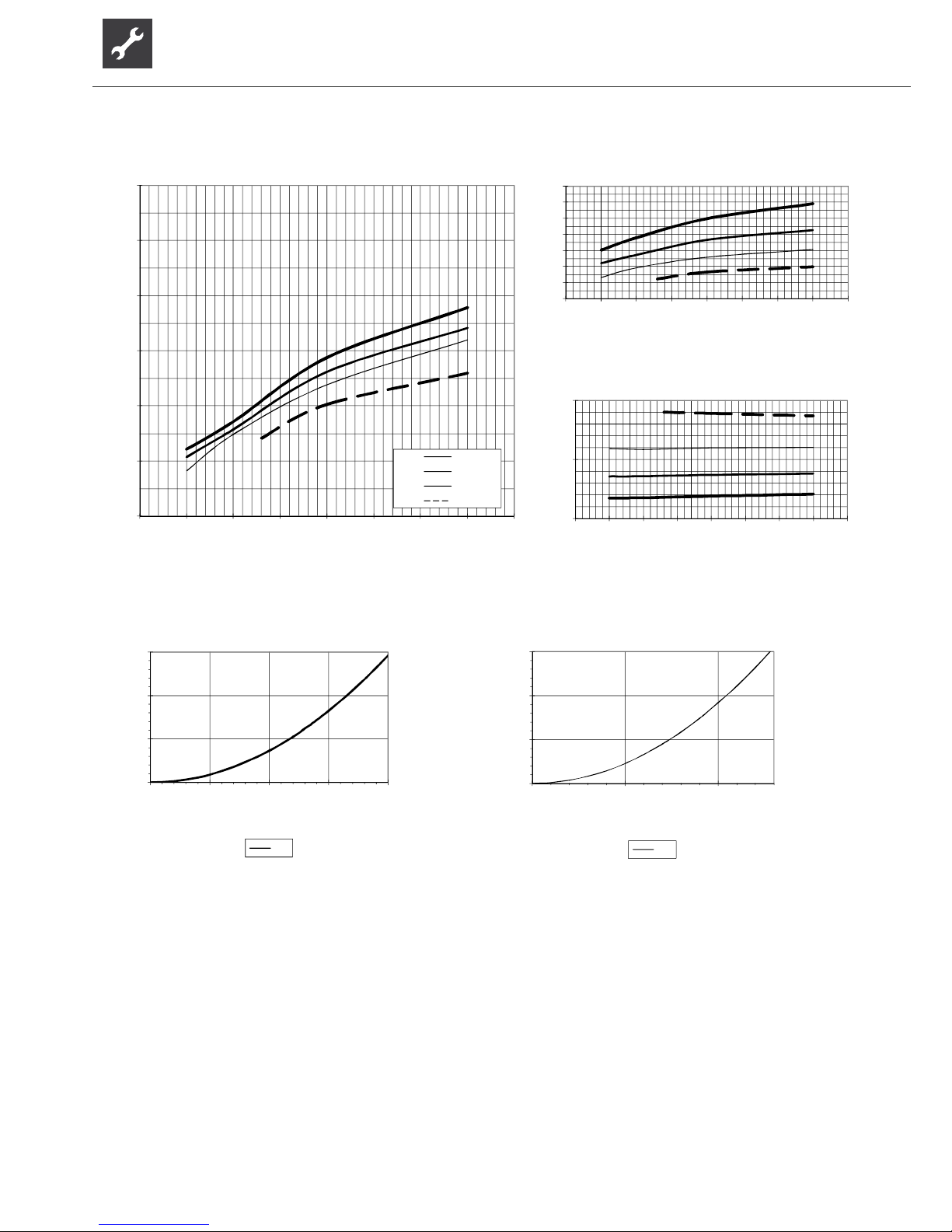
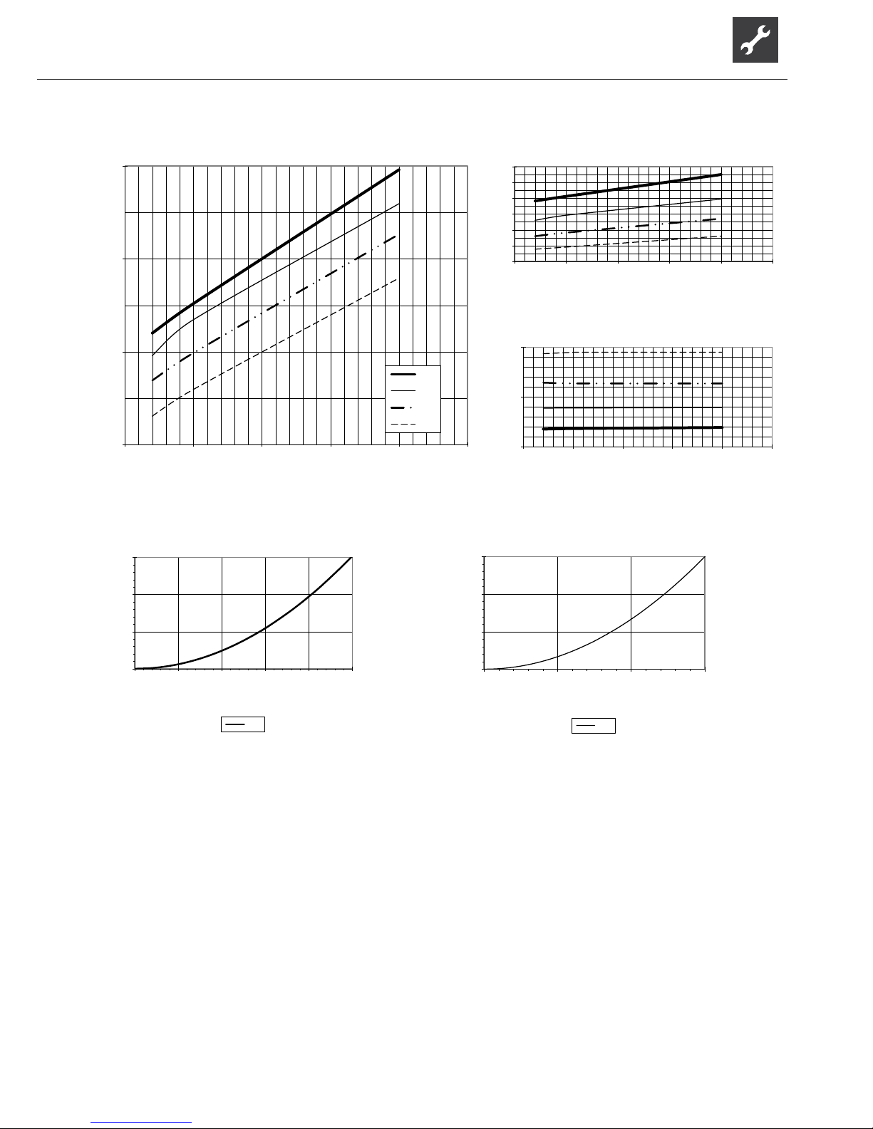
823077a
20
30
40
50
60
70
80
-10 -5 0 5 10 15 20 25 30
Temp„ (°C)
Qh (kW)
35°C
45°C
55°C
65°C
1
2
3
4
5
6
7
8
-10 -5 0 5 10 15 20 25 30
Temp„ (°C)
COP
6
11
16
-10 -5 0 5 10 15 20 25 30
Temp„ (°C)
Pe (kW )
0,0
0,1
0,2
0,3
0,0 2,5 5,0 7,5 10,0
“”[m3/h]
∆p (bar)
∆
p
”
0,0
0,1
0,2
0,3
0,0 5,0 10,0
“„[m3/h]
∆p (bar)
∆p„
Legend: UK823025L
“” Volume ow, heating water
“„ Volume ow, heat source
Temp „ Temperature, heat source
Qh Heating capacity
Pe Power consumption
COP Coefcient of performance / efciency rating
∆p” Pressure loss heat circuit
∆p„ Pressure loss heat source
VD Compressor(s)
SWP 371 Performance curves – Brine operation
Page 27
27
Subject to change without notice | 83053700gUK – Translation into English of the original German operating manual | ait-deutschland GmbH
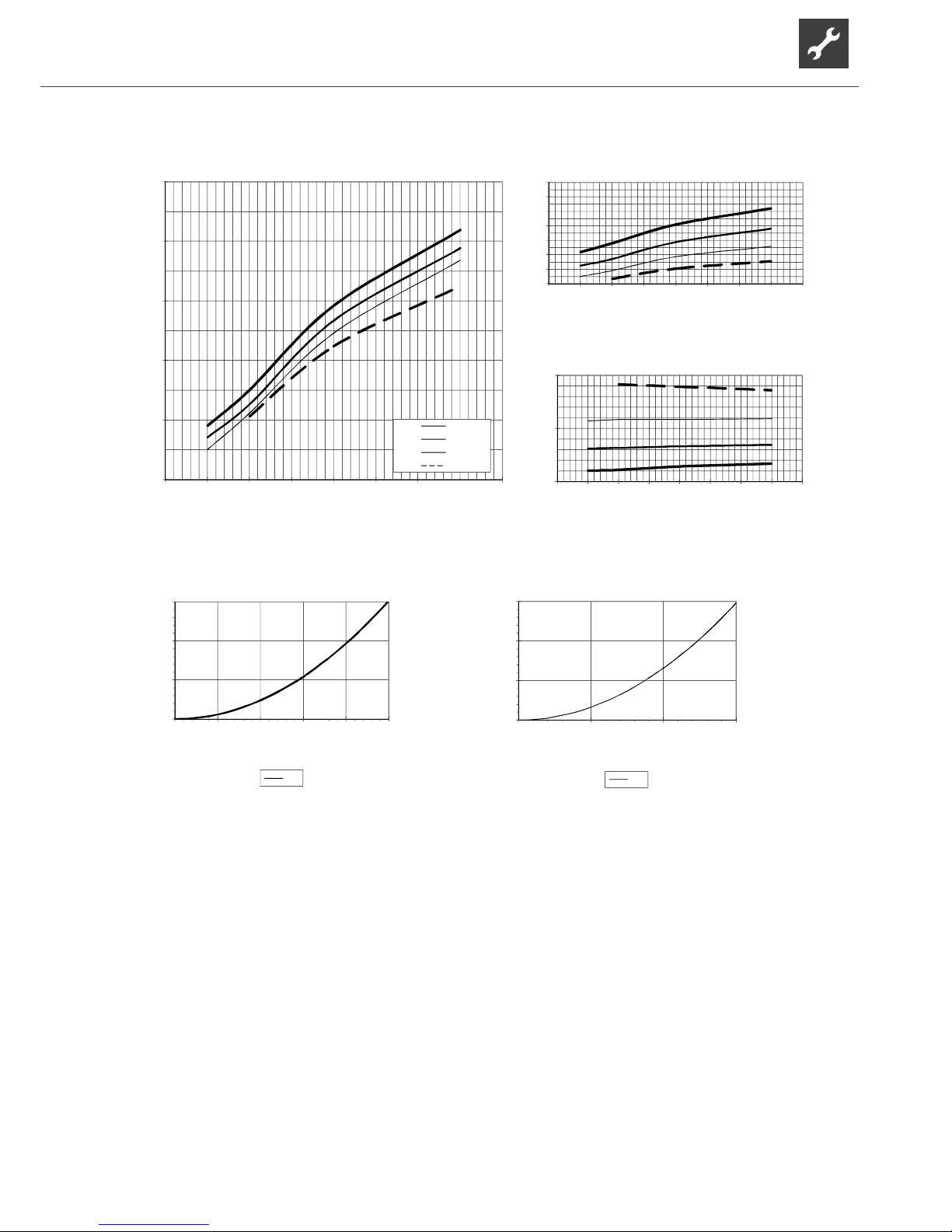
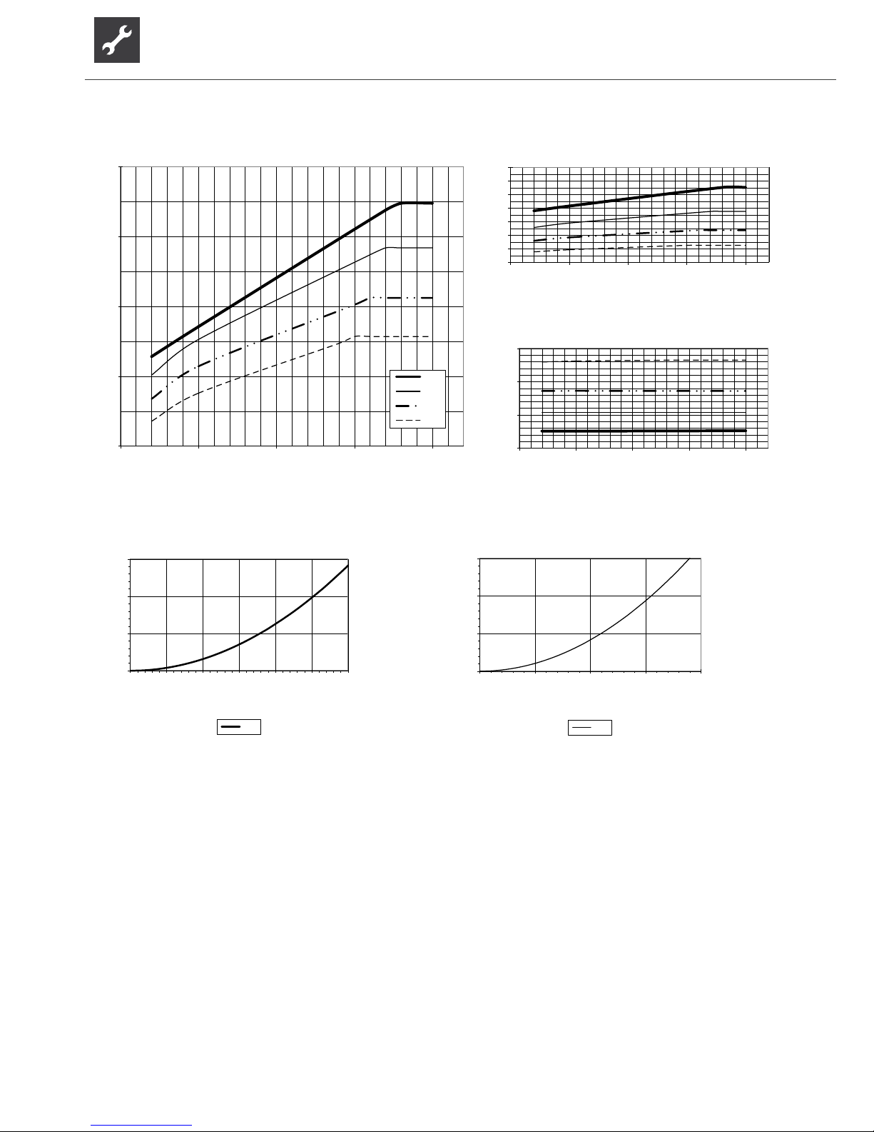
823078a
30
40
50
60
70
80
-10 -5 0 5 10 15 20 25 30
Temp„ (°C)
Qh (kW)
35°C
45°C
55°C
65°C
2
3
4
5
6
7
8
9
-10 -5 0 5 10 15 20 25 30
Temp„ (°C)
COP
8
13
18
-10 -5 0 5 10 15 20 25 30
Temp„ (°C)
Pe (kW )
0,0
0,1
0,2
0,3
0,0 2,5 5,0 7,5 10,0 12,5
“”[m3/h]
∆p (bar)
∆
p
”
0,0
0,1
0,2
0,3
0,0 5,0 10,0 15,0
“„[m3/h]
∆p (bar)
∆p„
Legend: UK823025L
“” Volume ow, heating water
“„ Volume ow, heat source
Temp „ Temperature, heat source
Qh Heating capacity
Pe Power consumption
COP Coefcient of performance / efciency rating
∆p” Pressure loss heat circuit
∆p„ Pressure loss heat source
VD Compressor(s)
Performance curves – Brine operation SWP 451
Page 28
28
Subject to change without notice | 83053700gUK – Translation into English of the original German operating manual | ait-deutschland GmbH
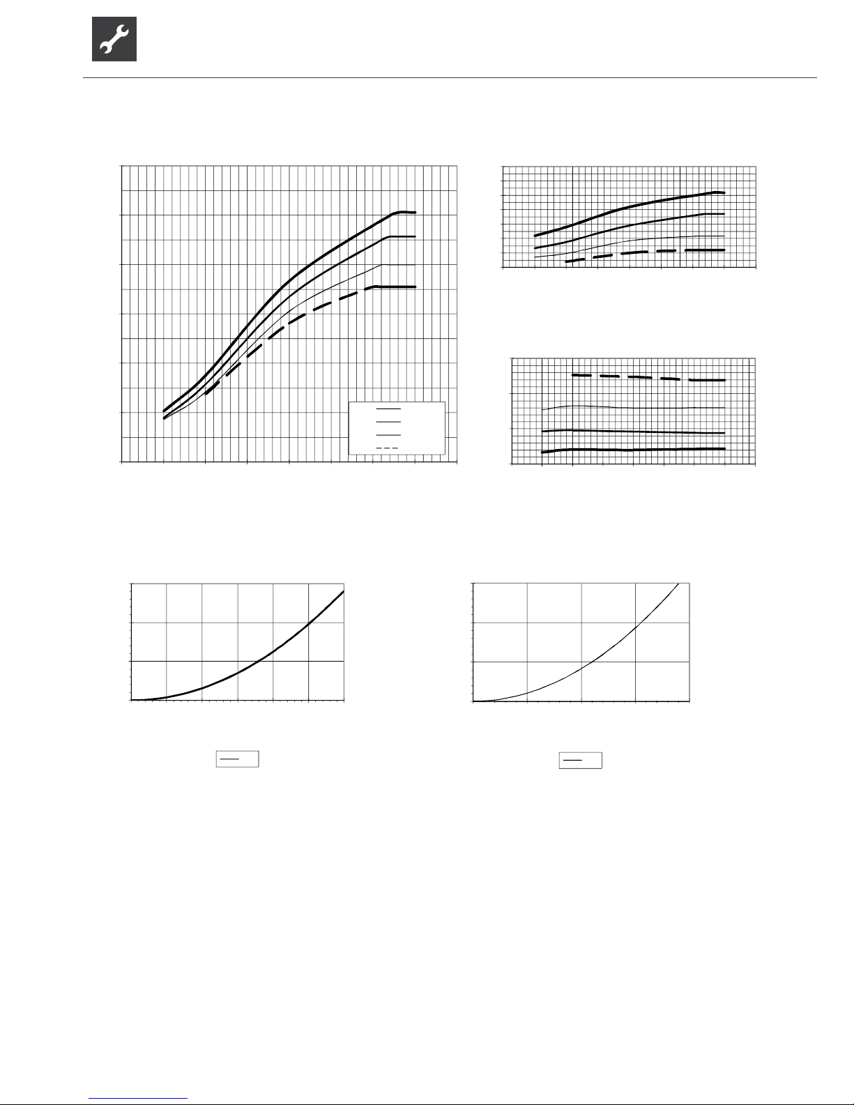
823079a
40
50
60
70
80
90
100
-10 -5 0 5 10 15 20 25 30
Temp„ (°C)
Qh (kW)
35°C
45°C
55°C
65°C
2
3
4
5
6
7
8
9
-10 -5 0 5 10 15 20 25 30
Temp„ (°C)
COP
10
15
20
25
-10 -5 0 5 10 15 20 25 30
Temp„ (°C)
Pe (kW )
0,0
0,1
0,2
0,3
0,0 2,5 5,0 7,5 10,0 12,5 15,0
“”[m3/h]
∆p (bar)
∆
p
”
0,0
0,1
0,2
0,3
0,0 5,0 10,0 15,0 20,0
“„[m3/h]
∆p (bar)
∆p„
Legend: UK823025L
“” Volume ow, heating water
“„ Volume ow, heat source
Temp „ Temperature, heat source
Qh Heating capacity
Pe Power consumption
COP Coefcient of performance / efciency rating
∆p” Pressure loss heat circuit
∆p„ Pressure loss heat source
VD Compressor(s)
SWP 581 Performance curves – Brine operation
Page 29
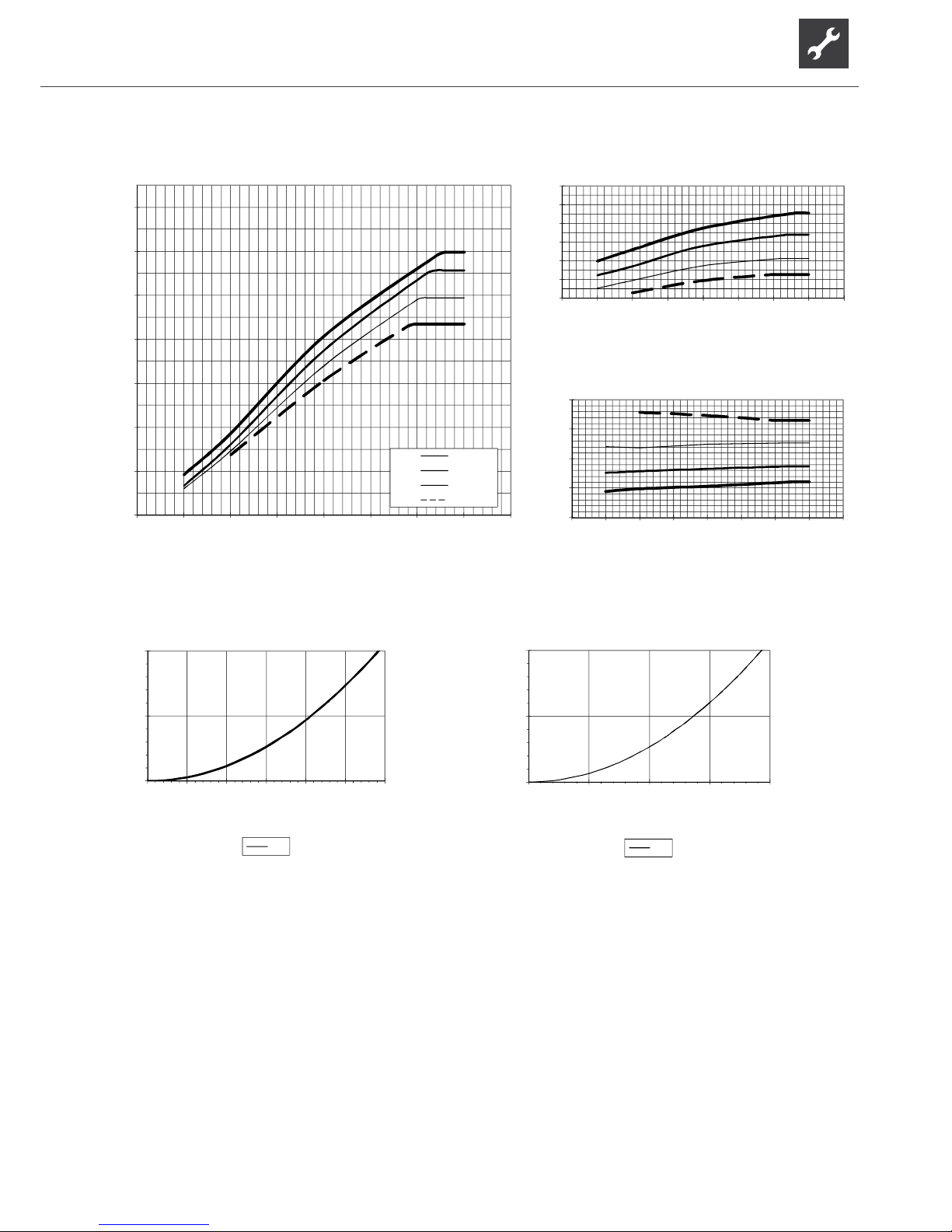
29
Subject to change without notice | 83053700gUK – Translation into English of the original German operating manual | ait-deutschland GmbH
823080a
50
60
70
80
90
100
110
120
-10 -5 0 5 10 15 20 25 30
Temp„ (°C)
Qh (kW)
35°C
45°C
55°C
65°C
2
3
4
5
6
7
8
-10 -5 0 5 10 15 20 25 30
Temp„ (°C)
COP
10
15
20
25
30
-10 -5 0 5 10 15 20 25 30
Temp„ (°C)
Pe (kW )
0,0
0,1
0,2
0,0 2,5 5,0 7,5 10,0 12,5 15,0
“”[m3/h]
∆p (bar)
∆
p
”
0,0
0,1
0,2
0,0 5,0 10,0 15,0 20,0
“„[m3/h]
∆p (bar)
∆p„
Legend: UK823025L
“” Volume ow, heating water
“„ Volume ow, heat source
Temp „ Temperature, heat source
Qh Heating capacity
Pe Power consumption
COP Coefcient of performance / efciency rating
∆p” Pressure loss heat circuit
∆p„ Pressure loss heat source
VD Compressor(s)
Performance curves – Brine operation SWP 691
Page 30
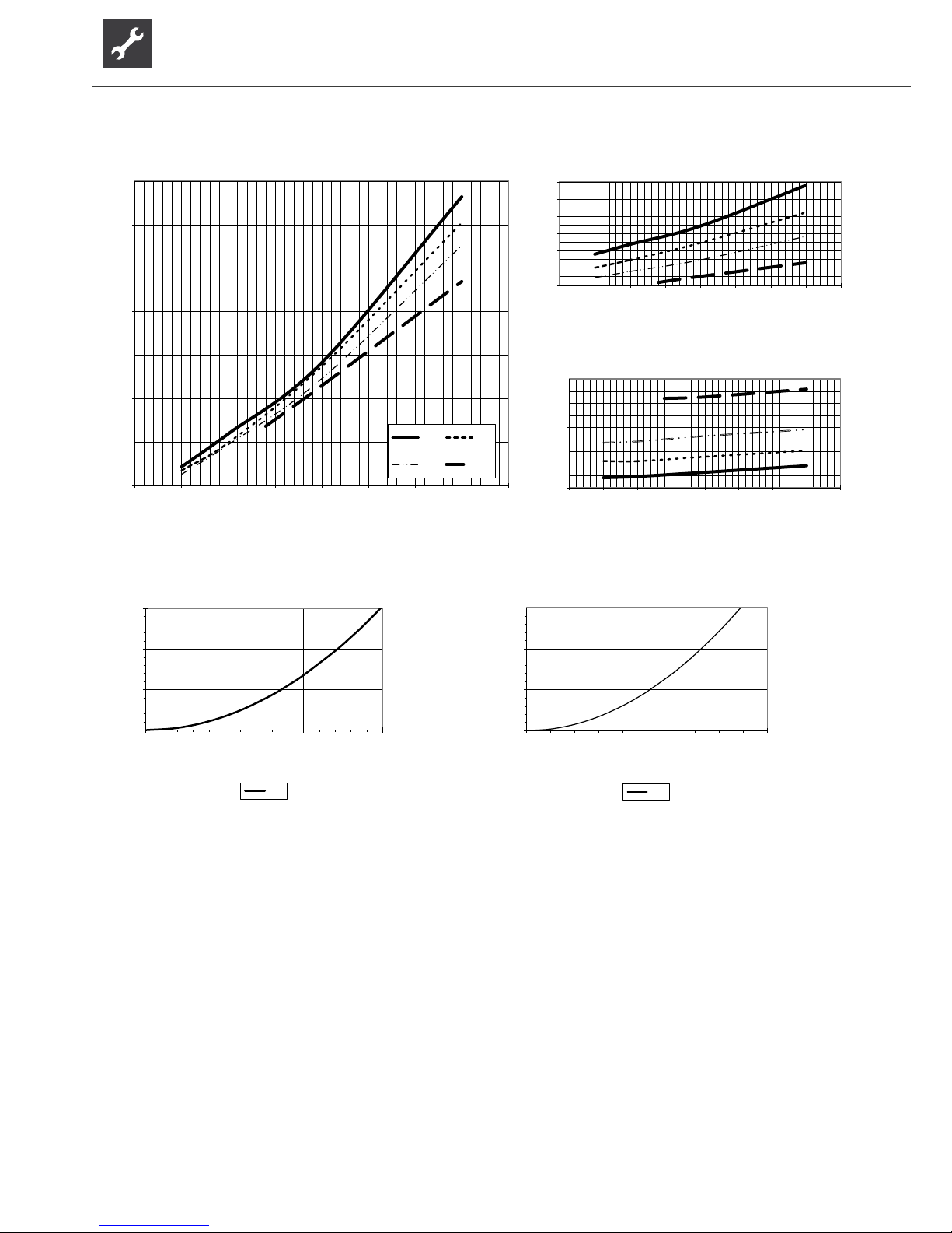
30
Subject to change without notice | 83053700gUK – Translation into English of the original German operating manual | ait-deutschland GmbH
Legende: DE823025L
823081a
20
30
40
50
-10 -5 0 5 10 15 20 25 30
Temp„ (°C)
Qh (kW )
35°C 45°C
55°C 70°C
2
3
4
5
6
7
8
-10 -5 0 5 10 15 20 25 30
Temp„ (°C)
COP
5
10
-10 -5 0 5 10 15 20 25 30
Temp„ (°C)
Pe (kW )
0,0
0,1
0,2
0,3
0,0 2,5 5,0 7,5
“”[m3/h]
∆p (bar)
Δp”
0,0
0,1
0,2
0,3
0,0 5,0 10,0
“„[m3/h]
∆p (bar)
Δp„
Legend: UK823025L
“” Volume ow, heating water
“„ Volume ow, heat source
Temp „ Temperature, heat source
Qh Heating capacity
Pe Power consumption
COP Coefcient of performance / efciency rating
∆p” Pressure loss heat circuit
∆p„ Pressure loss heat source
VD Compressor(s)
SWP 291H Performance curves – Brine operation
Page 31
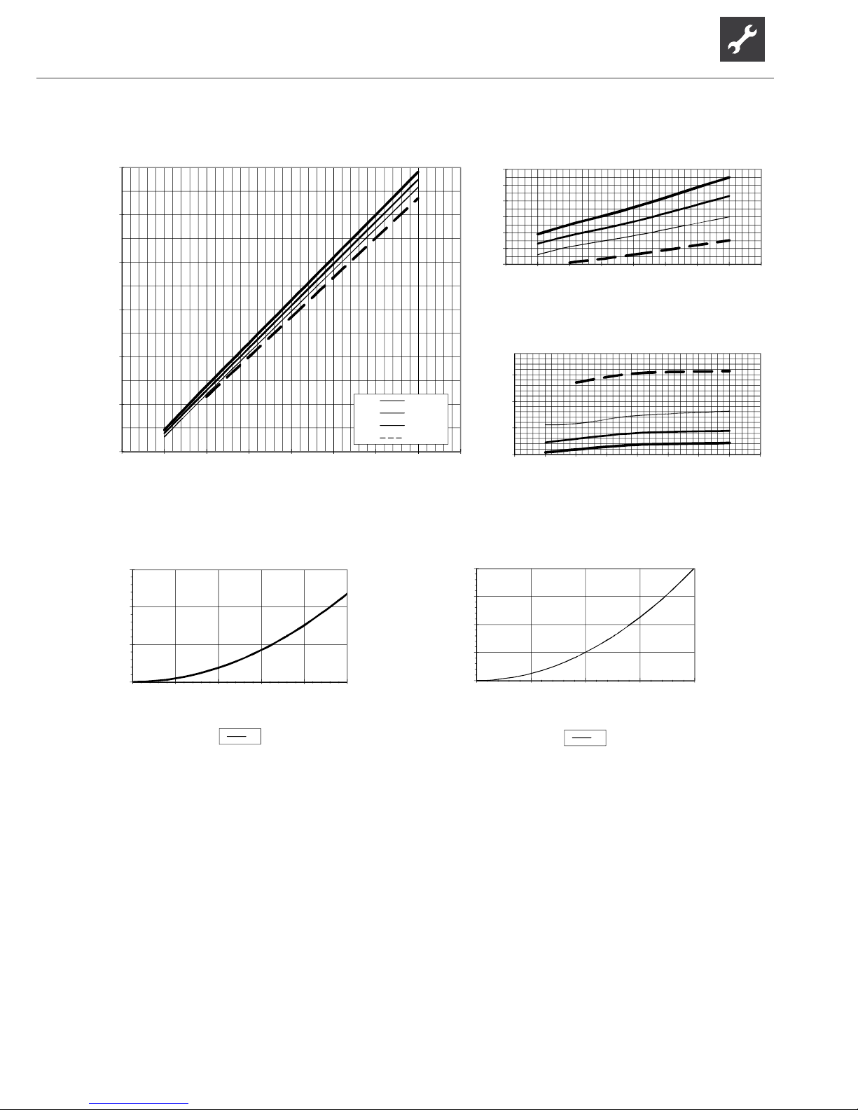
31
Subject to change without notice | 83053700gUK – Translation into English of the original German operating manual | ait-deutschland GmbH
Legend: UK823025L
“” Volume ow, heating water
“„ Volume ow, heat source
Temp „ Temperature, heat source
Qh Heating capacity
Pe Power consumption
COP Coefcient of performance / efciency rating
∆p” Pressure loss heat circuit
∆p„ Pressure loss heat source
VD Compressor(s)
823082
40
50
60
70
80
90
100
-10 -5 0 5 10 15 20 25 30
Temp„ (°C)
Qh (kW)
35°C
45°C
55°C
70°C
2
3
4
5
6
7
8
-10 -5 0 5 10 15 20 25 30
Temp„ (°C)
COP
11
16
21
26
-10 -5 0 5 10 15 20 25 30
Temp„ (°C)
Pe (kW )
0,0
0,1
0,2
0,3
0,0 2,5 5,0 7,5 10,0 12,5
“”[m3/h]
∆p (bar)
∆
p
…
0,0
0,1
0,2
0,3
0,4
0,0 5,0 10,0 15,0 20,0
“„[m3/h]
∆p (bar)
∆
p
…
Performance curves – Brine operation SWP 561H
Page 32
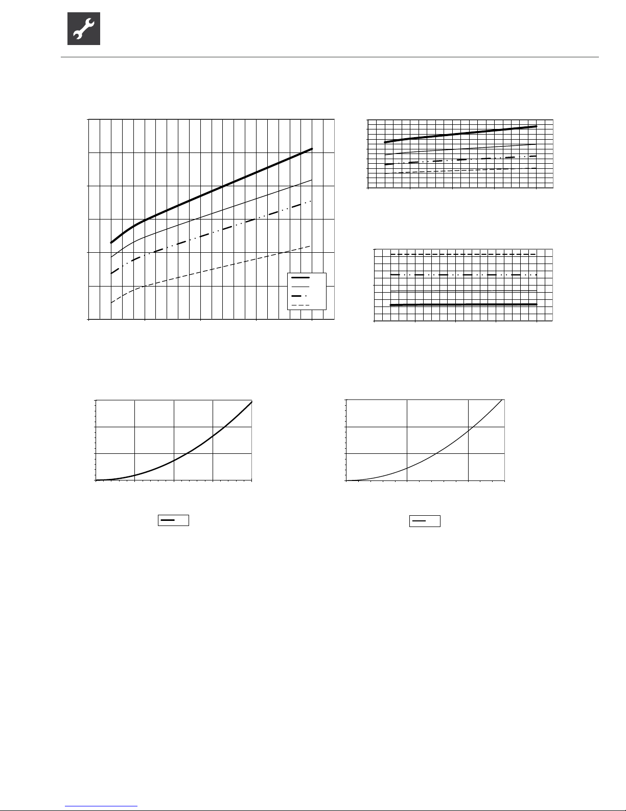
32
Subject to change without notice | 83053700gUK – Translation into English of the original German operating manual | ait-deutschland GmbH
Legend: UK823025L
“” Volume ow, heating water
“„ Volume ow, heat source
Temp „ Temperature, heat source
Qh Heating capacity
Pe Power consumption
COP Coefcient of performance / efciency rating
∆p” Pressure loss heat circuit
∆p„ Pressure loss heat source
VD Compressor(s)
823077a
35
45
55
65
5 10 15 20 25
Temp„ (°C)
Qh (kW )
35°C
45°C
55°C
65°C
1
2
3
4
5
6
7
8
5 10 15 20 25
Temp„ (°C)
COP
6
11
16
5 10 15 20 25
Temp„ (°C)
Pe (kW )
0,0
0,1
0,2
0,3
0,0 2,5 5,0 7,5 10,0
“”[m3/h]
∆p (bar)
Δp”
0,0
0,1
0,2
0,3
0,0 5,0 10,0
“„[m3/h]
∆p (bar)
Δp„
SWP 371 Performance curves – Water operation
Page 33
33
Subject to change without notice | 83053700gUK – Translation into English of the original German operating manual | ait-deutschland GmbH
Legend: UK823025L
“” Volume ow, heating water
“„ Volume ow, heat source
Temp „ Temperature, heat source
Qh Heating capacity
Pe Power consumption
COP Coefcient of performance / efciency rating
∆p” Pressure loss heat circuit
∆p„ Pressure loss heat source
VD Compressor(s)
823078a
45
55
65
75
5 10 15 20 25 30
Temp„ (°C)
Qh (kW )
35°C
45°C
55°C
65°C
2
3
4
5
6
7
8
5 10 15 20 25 30
Temp„ (°C)
COP
8
13
18
5 10 15 20 25 30
Temp„ (°C)
Pe (kW )
0,0
0,1
0,2
0,3
0,0 2,5 5,0 7, 5 10,0 12,5
“”[m3/h]
∆p (bar)
Δp”
0,0
0,1
0,2
0,3
0,0 5,0 10,0 15,0
“„[m3/h]
∆p (bar)
Δp„
Performance curves – Water operation SWP 451
Page 34
34
Subject to change without notice | 83053700gUK – Translation into English of the original German operating manual | ait-deutschland GmbH
Legend: UK823025L
“” Volume ow, heating water
“„ Volume ow, heat source
Temp „ Temperature, heat source
Qh Heating capacity
Pe Power consumption
COP Coefcient of performance / efciency rating
∆p” Pressure loss heat circuit
∆p„ Pressure loss heat source
VD Compressor(s)
823079a
60
70
80
90
100
5 10 15 20 25
Temp„ (°C)
Qh (kW )
35°C
45°C
55°C
65°C
2
3
4
5
6
7
8
9
5 10 15 20 25
Temp„ (°C)
COP
10
15
20
25
5 10 15 20 25
Temp„ (°C)
Pe (kW )
0,0
0,1
0,2
0,3
0,0 2,5 5,0 7,5 10,0 12,5 15,0
“”[m3/h]
∆p (bar)
Δp”
0,0
0,1
0,2
0,3
0,0 5,0 10,0 15,0 20,0
“„[m3/h]
∆p (bar)
Δp„
SWP 581 Performance curves – Water operation
Page 35
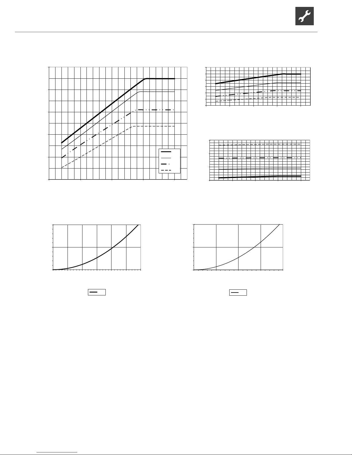
35
Subject to change without notice | 83053700gUK – Translation into English of the original German operating manual | ait-deutschland GmbH
Legend: UK823025L
“” Volume ow, heating water
“„ Volume ow, heat source
Temp „ Temperature, heat source
Qh Heating capacity
Pe Power consumption
COP Coefcient of performance / efciency rating
∆p” Pressure loss heat circuit
∆p„ Pressure loss heat source
VD Compressor(s)
823080a
70
80
90
100
110
120
5 10 15 20 25
Temp„ (°C)
Qh (kW )
35°C
45°C
55°C
65°C
2
3
4
5
6
7
8
5 10 15 20 25
Temp„ (°C)
COP
15
20
25
30
5 10 15 20 25
Temp„ (°C)
Pe (kW )
0,0
0,1
0,2
0,0 2,5 5,0 7,5 10,0 12,5 15,0
“”[m3/h]
∆p (bar)
Δp”
0,0
0,1
0,2
0,0 5,0 10,0 15,0 20,0
“„[m3/h]
∆p (bar)
Δp„
Performance curves – Water operation SWP 691
Page 36
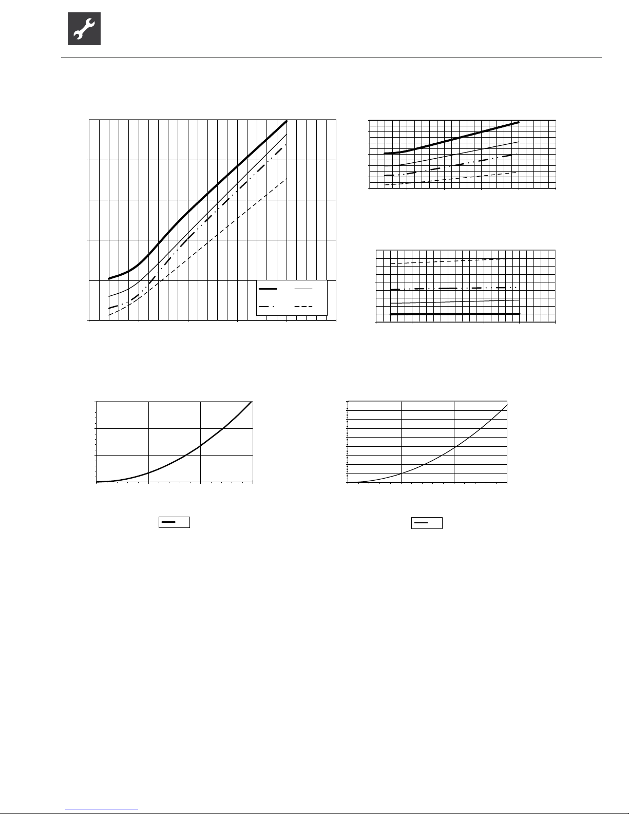
36
Subject to change without notice | 83053700gUK – Translation into English of the original German operating manual | ait-deutschland GmbH
Legend: UK823025L
“” Volume ow, heating water
“„ Volume ow, heat source
Temp „ Temperature, heat source
Qh Heating capacity
Pe Power consumption
COP Coefcient of performance / efciency rating
∆p” Pressure loss heat circuit
∆p„ Pressure loss heat source
VD Compressor(s)
823081
30
40
50
5 10 15 20 25 30
Temp„ (°C)
Qh (kW )
35°C 45°C
55°C 70°C
2
3
4
5
6
7
8
5 10 15 20 25 30
Temp„ (°C)
COP
6
11
5 10 15 20 25 30
Temp„ (°C)
Pe (kW )
0,0
0,1
0,2
0,3
0,0 2,5 5,0 7,5
“”[m3/h]
∆p (bar)
Δp”
0,0
0,1
0,2
0,3
0,4
0,5
0,6
0,7
0,8
0,9
0,0 5,0 10,0 15,0
“„[m3/h]
∆p (bar)
Δp„
SWP 291H Performance curves – Water operation
Page 37
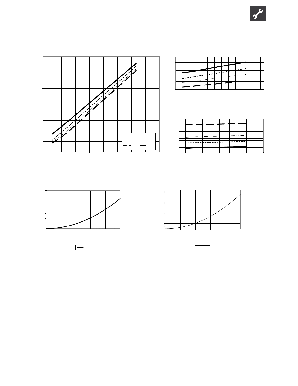
37
Subject to change without notice | 83053700gUK – Translation into English of the original German operating manual | ait-deutschland GmbH
Legend: UK823025L
“” Volume ow, heating water
“„ Volume ow, heat source
Temp „ Temperature, heat source
Qh Heating capacity
Pe Power consumption
COP Coefcient of performance / efciency rating
∆p” Pressure loss heat circuit
∆p„ Pressure loss heat source
VD Compressor(s)
823082
60
70
80
90
100
5 10 15 20 25 30
Temp„ (°C)
Qh (kW )
35°C 45°C
55°C 70°C
2
3
4
5
6
7
8
5 10 15 20 25 30
Temp„ (°C)
COP
11
16
21
26
5 10 15 20 25 30
Temp„ (°C)
Pe (kW )
0,0
0,1
0,2
0,3
0,0 2,5 5,0 7, 5 10,0 12,5
“”[m3/h]
∆p (bar)
Δp”
0,0
0,1
0,2
0,3
0,4
0,5
0,6
0,7
0,0 5,0 10,0 15,0 20,0 25,0
“„[m3/h]
∆p (bar)
Δp„
Performance curves – Water operation SWP 561H
Page 38
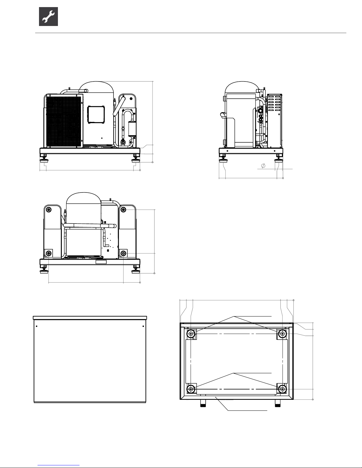
38
Subject to change without notice | 83053700gUK – Translation into English of the original German operating manual | ait-deutschland GmbH
D
0
131
1219
1340
1350
10
0
123
781
902
912
E
0,18N/mm²
0,32N/mm²
0,005N/mm²
0
1190511139
0
100
170
961
A
87
0
51
709
760
B
0
237
756
0
198
1084
C
5
4
3
2
1
Legend: EN819407
All dim ensions in mm.
A
Front view
B
Side vi ew from left
C
Rear view
D
Front view with facing
E
View from underneath with facing
SWP 371 – SWP 691 Dimensional drawings - moving dimensions
Page 39
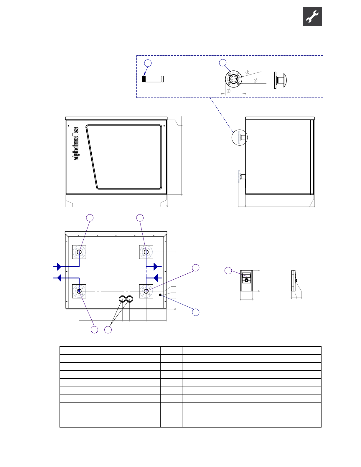
39
Subject to change without notice | 83053700gUK – Translation into English of the original German operating manual | ait-deutschland GmbH
0
1030
990
0
10
1340
1350
A
0
97
912
902
B
0
135
756
190
0
81
266
485
580
1152
237
3
7
6
5
4
E
2
0
275
0
159
G
1
H
0
47
70
165
4x
18
125
8
9
I
Pos.
Bezeichnung
1
Bedienteil (für Wandmontage, im Beipack)
5
4
3
2
1
Legend: EN819406a Item Designation
1 Control element (for wall mounting, in extra box)
A Front view” 2 Penetration for connection and LIN bus cable
B Side view from lef 3 Penetration for electric cable
E Rear view 4 Heat source outlet (from heat pump)
G Front view, control 5 Heat source inlet (in heat pump)
H Side view from left, control 6 Heating water outlet (ow)
I Connection options 7 Heating water inlet (return)
8 Flange DN50 PN10/16
9
male thread
Dimensional drawings with housing SWP 371 – SWP 691
Page 40
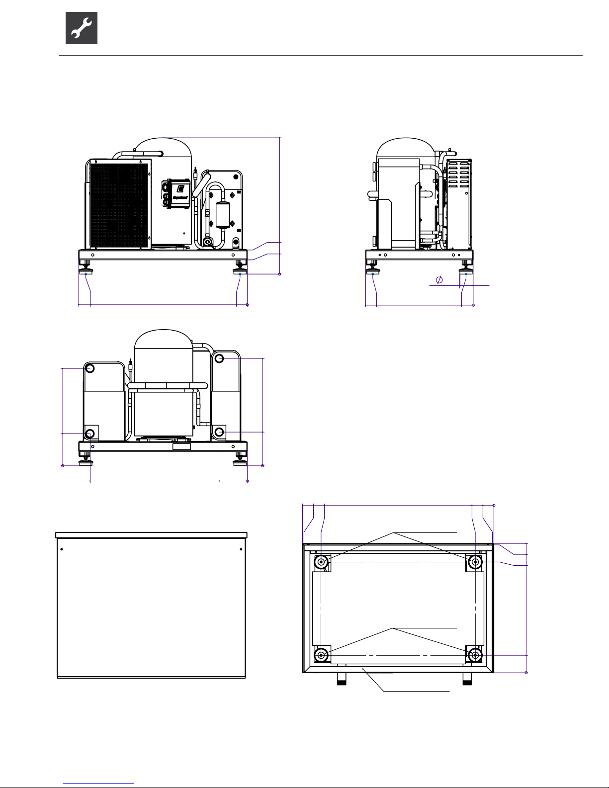
40
Subject to change without notice | 83053700gUK – Translation into English of the original German operating manual | ait-deutschland GmbH
D
0
131
1219
1340
1350
10
0
123
781
902
912
E
0,18N/mm²
0,32N/mm²
0,005N/mm²
0
237
756
0
226
686
0
1110
198
C
0
51
1139
1190
0
170
100
961
A
87
0
51
709
760
B
5
4
3
2
1
Legend: UK819416
All dimensions in mm.
A
Front view
B
Side view from left
C
Rear view
D
Front view with facing
E
View from underneath with
facing
SWP 291H – SWP 561H Dimensional drawings - moving dimensions
Page 41
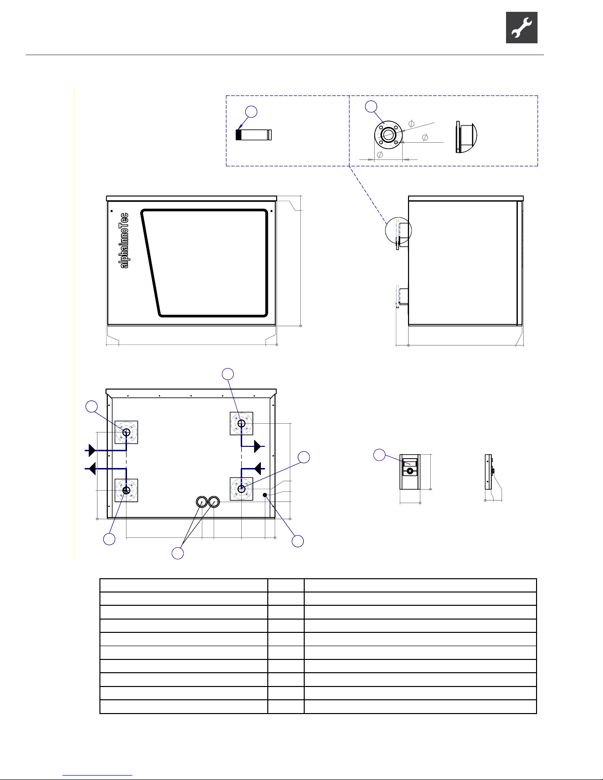
41
Subject to change without notice | 83053700gUK – Translation into English of the original German operating manual | ait-deutschland GmbH
0
1030
990
0
10
1340
1350
A
0
97
912
902
B
0
135
756
190
0
81
266
485
580
237
0
226
686
3
6
E
2
7
4
5
0
275
0
159
G
1
0
47
70
H
165
4x
18
125
8
9
I
5
4
3
2
1
Legend: EN819414a Item Designation
1 Control element (for wall mounting, in extra box)
A Front view” 2 Penetration for connection and LIN bus cable
B Side view from lef 3 Penetration for electric cable
E Rear view 4 Heat source outlet (from heat pump)
G Front view, control 5 Heat source inlet (in heat pump)
H Side view from left, control 6 Heating water outlet (ow)
I Connection options 7 Heating water inlet (return)
8 Flange DN50 PN10/16
9
male thread
Dimensional drawings with housing SWP 291H – SWP 561H
Page 42
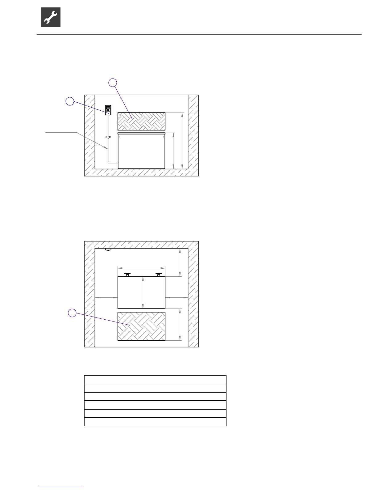
42
Subject to change without notice | 83053700gUK – Translation into English of the original German operating manual | ait-deutschland GmbH
1030
>
1600
A
1
2
max. 13m
>
800
912
>
900
>500 >500
1350
B
1
5
4
3
2
1
Legend: EN819408
A Front view
B Plan view
1 Hatched area = space for service purposes
2 Control element
SWP 371 – 691 / SWP 291H – 561H Installation plan 1
Page 43
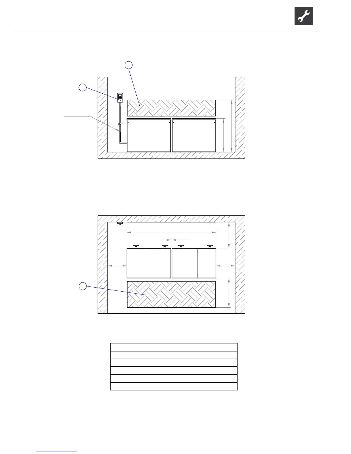
43
Subject to change without notice | 83053700gUK – Translation into English of the original German operating manual | ait-deutschland GmbH
>
1600
1030
A
1
2
>
800
912
>
900
>
2730
>
30
>500>500
B
1
max.13m
5
4
3
2
1
Legend: EN819409
A Front view
B Plan view
1 Hatched area = space for service purposes
2 Control element
Installation plan 2 SWP 371 – 691 / SWP 291H – 561H
Page 44
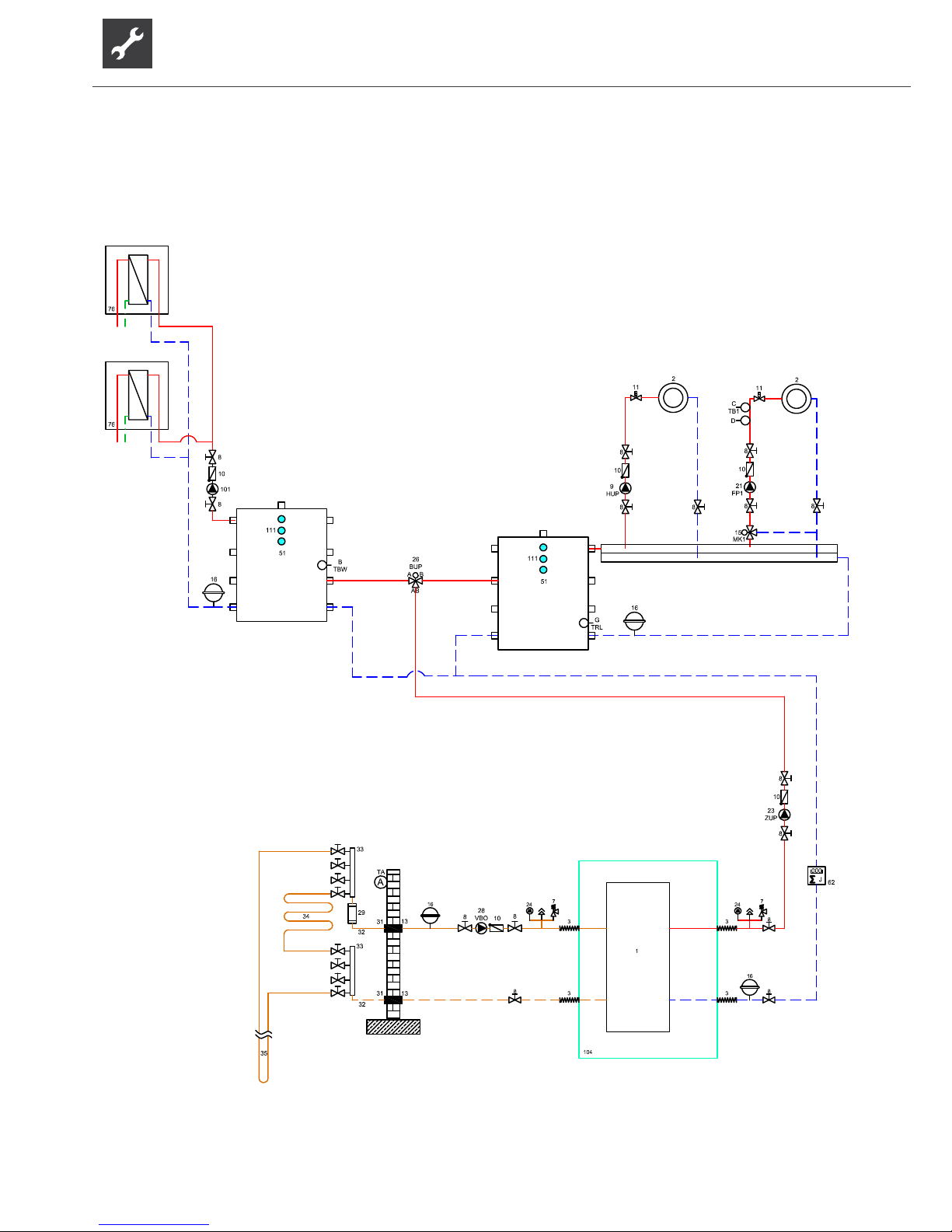
44
Subject to change without notice | 83053700gUK – Translation into English of the original German operating manual | ait-deutschland GmbH
SWP 371 – 691 / SWP 291H – 561H Separate buffer tank
Page 45

45
Subject to change without notice | 83053700gUK – Translation into English of the original German operating manual | ait-deutschland GmbH
Legend hydraulic diagramm
140304
1 Heat pump 51 Seperation tank TA/
A
External sensor
2 Underfloor heating / radiators 52 Gas- or oil-boiler TBW/B Domestic hot water sensor
3 Vibration isolation 53 Wood boiler TB1/C Feedwater sensor mixer circuits 1
4 Sylomer strip machine underlay 54 Hot water cylinder D Floor tmperature limiter
5 Closure and drainage 55 Brine pressure switch TRL/G Sensor external return
6 Expansion vessel packing list 56 Swimming pool heat exchanger ST
A
Line pressure regulator valve
7 Safety valve 57 Geothermal heat exchanger
TRL/H Sensor return
(
h
y
draulic module, dual
)
8 Closure 58 Ventilation system
9 Heating circulation pump 59 Plate heat exchanger 79
Motor valve
10 Non return valve/ one way valve 61 Cooling cylinder 80
Mixin
g
valve
11 Individual room regulation 65 Compact distributor 81
S
p
lit heat
p
um
p
outdoor unit
12 Overflow valve 66 Fancoils 82
S
p
lit heat
p
um
p
indoor unit
13 Steamtight insulation 67 Solar/ service water cylinder 83
Circulation
p
um
p
14 Service water circulation pump 68 Solar/ service water cylinder 84
Switchin
g
valve
15 Mixer circuit three-way mixer (MK1 discharge) 69 Multifunction tank 113 Connection 2nd heat generator
16 Expansion vessel supplied by customer 71 Dual hydraulic module
BT1 Outdoor tem
p
erature sensor
18 Heating rod (heating) 72 Buffer tank wall mounted
BT2 Flow tem
p
erature sensor
19 Mixer circuit four-way mixer (MK1 charge) 73 Pipe lead-in
BT3 Return tem
p
erature sensor
20 Heating rod (SW) 74 Ventower
BT6 Domestic hot water tem
p
erature sensor
21 Mixer circuit circulation pump (FP1) 75 Scope of delivery, hydraulic tower, dual
BT12 Flow tem
p
erature li
q
uefier
23
Feed circulating pump (reconnect the integrated circulating pump
in the heat pump)
76
Fresh water station
BT19 Temperature sensor immersion heater
24 Manifuld 77 Scope of supply water/water booster
BT24 Tem
p
erature sensor 2nd heat
g
enerator
25 Heating circulation pump 78 Accessories water/water booster optional
26
Switching valve (heating/service water)(B = normally open)
27 Heating element
28 Brine circulation pump Comfort board:
29 Dirt-trap 0.6 mm mesh
15 Mixer circuit three-wa
y
mixer
(
MK2-3 dischar
g
e
)
30 Spill-tray für brine mix 100 Room thermostat for cooling (optional) 17 Temperature difference regulator
31 Wall breakthrough 101 Controls supplied by customer 19 Mixer circuit four-way mixer (MK2 charge)
32 Inlet pipe 102 Dew-point monitor (optional) 21 Mixer circuit circulation pump (FP2-3)
33 Brine manifuld 103 Room thermostat for reference space in packing list 22 Swimming pool circulating pump
34 Ground collector 104 Supply heat pump 44 Three-way mixer valve (cooling function MK2)
35 Ground slinkies 105 Cooling circuit module box removeable for installation 47
Changeover valve swimming bath preparation(B = normally open)
36 Groundwater spring pump 106 Specific glycole mixture 60 Changeover valve cooling operation(B = normally open)
37 Wall bracket 107 Scald protection / thermostatic mixer valve 62 Heat meter (optional)
38 Flow switch 108 Solar pump assembly 63 Changeover valve solar circuit(B = normally open)
39 Suction well 109 Overflow valve must be closed 64 Cooling circulation pump
40 Inverted well 110 Packing list hydraulic tower 70 Solar seperation module
41 Rinse fitting heating circuit 111 Mounting for additional heating element TB2-3/C Feedwater sensor mixer circuits 2-3
42 Circulation pump 112 Minimum distance to thermal decoupling of the mixing valve TSS/E Sensor, temperature difference control (low temperature)
43 Brine / Water heat exchanger (cooling function) TSK/E Sensor, temperature difference control (high temperature)
44 Three-way mixer valve (cooling function MK1) TEE/F Sensor external energy source
45 Cap valve
46 Filler and drainage valve
48 Domestic hot water charging pump
49 Direction of groundwater flow
50 Buffer storage
Important notice !
These hydraulic diagrams are schematic representations and are for assistance only. They do not relieve of the obligation to carry out appropriate planning! They do not include all necessary shut-off valves, ventilator
fittings or safety devices. These must be incorporated in accordance with the standards and regulations applicable to the respective installation. All country-specific standards, laws and regulations must be observed! The
tubes have to be dimensioned according to the nominal volume flow of the heat pump resp. the free pressing of the integrated circulating pump. For detailed information and advice please contact our local sales partner!
Page 46
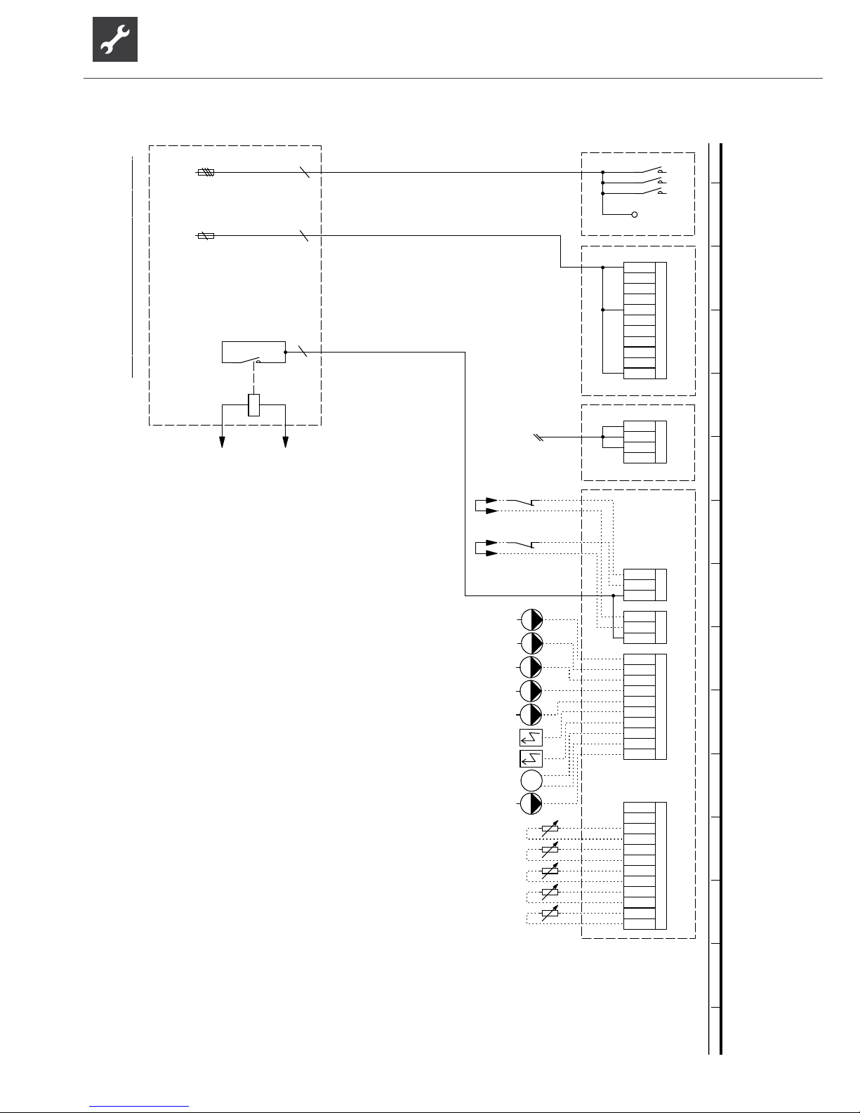
46
Subject to change without notice | 83053700gUK – Translation into English of the original German operating manual | ait-deutschland GmbH
1
2
-F11
3
4
5
6
-F12
A1
A2
FP1
EVU
FP1
Sub-distribution unit internal installation
ASD
PEX
TA
L1
Pump for mixing circuit 1
Legend:
MA1/MIS
HUP
Charge/discharge/cooling mixer 1 closed
EVU
X0-X4
Hot water gauge/thermostat
Heating circuit circulating pump
TBW
Accessories: Remote control
TRL
VBO
PEX
ZW1
GND
Q0:L1,L2,L3,PE
Controller board; Attention: I-max = 6A/230VAC
3
TB1
External return sensor
GND
MOT
Hot water circulating pump/switching valve
TRL
ZUP
ZW1
3~PE/400V/50Hz
Terminal strips on controller board
Function
Q0
Terminals in heat pump switchbox
External flow rate switch; bridge if no switch is connected.
N
Main contactor; mains power 3~PE/400V/50Hz
M
RFV
X10
Q0
BUP
RFV
2
F11
L1
GND
Energy supplier contact; closed on release; bridge if no blocking interval
A5
TA
-X3
N
MIS
MZ1
GND
-X2
EVU
Control signal of additional heat generator 1
MOT
ZIP
X10:L,N,PE
N
TBW
N
X10
1~N/PE/230V/50Hz
TB1
Sensor mixing circuit 1
PE
ZUP
4
SWP
VBO
A1
F12
A5
Cut out controller unit
A2
A1
connection control unit
L
-X
LIN
Name
External sensor
ZW2/SST
ZW2/SS T
TA
Single pole miniature circuit-breaker of compressor to IEC 60947-2; Important: Clockwise rotary field is absolutely essential!
L1
Auxiliary circulation pump
L2
No function
Control signal of additional heat generator 2 (alternative is general malfunction)
HUP
PE
-X10
DFS
PE
Brine pump
TB1
PE
PE
MA1
HUP
Power supply controller 230V
ZUP
Terminal strip in switchbox of heat pump; N/PE distribution for external 230V units
TBW
UK831175
N
Connection of external motor protection; bridge if no external motor protection is connected.
PE
FP1
L1
DFS
ZIP
Control element
RFV
ZW2
Power supply compressor; 3x400V; Important: Clockwise rotary field is absolutely necessary!
-X4
Terminals
GND
MZ1/MIS
VBO
A2
MOT
TRL
Charge/discharge/cooling mixer 1 open
3
2
-X0
LIN
ZW1
Information on fuses can be found in the technical data
GND
L3
BUP
circulation pump
ZIP
X10
BUP
1
1 2 3 4 5 6 7 8 9 10 11 12 13 14 15
SWP 371 – 691 / SWP 291H – 561H Terminal diagram
Page 47
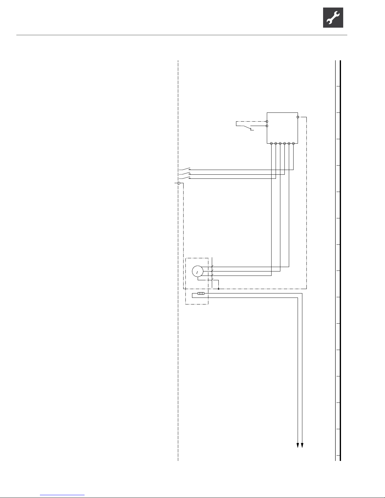
47
Subject to change without notice | 83053700gUK – Translation into English of the original German operating manual | ait-deutschland GmbH
PE
IN 0V
L1UL2VL3
W
-Q11
14 12
11
-K1
/2.4
1
2
-Q0
/2.5
3
4
5
6
PE
-X10
M
3
T1 T2 T3 PE
-M1
VD1
-E20
E20
/2.1N/2.1
2
Q0
Mains contactor, compressor
VD1
Q11
Legend:
PE
UK817379a
3~PE/400V/50Hz
E20
-M1
Operating materials
VD1
compressor
Starting current limit compressor
K1
M1
1
L1,L2,L3,PE; power supply, output, compressor; clockwise rotary field is absolutely necessary!
L3L2L1
3
Function
Sump heating for compressor 1
3~PE/400V/50Hz
auxiliary relay compressor
X10
Terminal in switch box heat pump
1 2 3 4 5 6 7 8 9 10 11 12 13 14 15
Circuit diagram 1/3 SWP 371 / SWP 451
Page 48
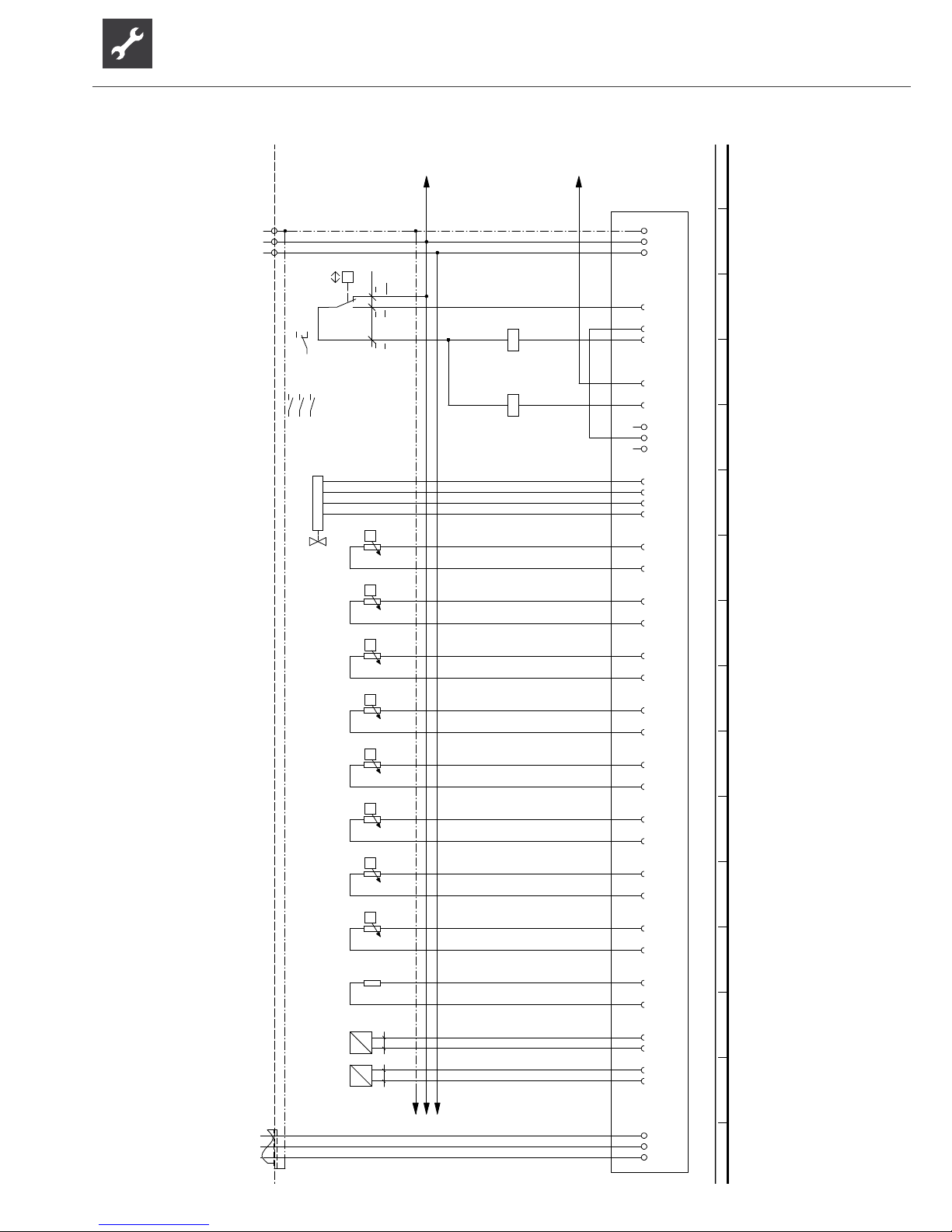
48
Subject to change without notice | 83053700gUK – Translation into English of the original German operating manual | ait-deutschland GmbH
E20
/1.15
N
/1.15,15
PE
-X1
PE
-X10
N
N
L
L
P
+-
b2 c4
a1
-F1
HDP
DI1
-X2
DI2
OUT1
A1
A2
-K1
OUT4
OUT5
A1
A2
-Q0
L..
-X4
L..
L..
B/
-X6
A
Green
Yellow
white
Brown
-K22
A/ B
ϑ
NT1
-X7
-R1
TSG1
GND
ϑ
NT2
-R2
TVD
GND
ϑ
NT3
-R3
TWE
GND
ϑ
NT4
-R4
THG
GND
ϑ
NT5
-R5
TSG2
GND
ϑ
NT6
-R6
TVL
GND
ϑ
NT7
-R7
TRL
GND
ϑ
NT8
-R8
TWA
GND
NT9
-R9
CW
GND
GND
-X8
I
P
12
-B10
HD
AIN1
GND
I
P
12
-B11
ND
AIN2
L
/3.1N1,/3.1PE/3.1
3
-X11
2
321
PE
1
12
/1.5
34
/1.5
56
/1.5
12
14
11
/1.3
UK817379a
TWE
Q0
2
TSG1
R2
High-pressure switch
TRL
TSG2
R8
B10 HD
Controller board; Attention: I-max = 6A/230VAC
VD1
3
auxiliary relay compressor
Hot gas sensor
230VAC
R1
Coder resistance; 11, 0 kOhm
-F1
K1
Sump heating sensor
GND/LIN/12V
Legend:R41~N/PE/230V/50Hz
K22
HDP
R9
K20
F1
r
t
High-pressure sensor
-K20
1~N/PE/230V/50Hz
THG
1
TVL
s
w
2
Heat source input sensor
Suction sensor, compressor
1
TVD
4123
CW
TWA
R5
Terminal in switch box heat pumpX10
Function
L,N,PE; power supply, controller
R3
Electronic expansion valve
ND
Heat source output sensor
Low pressure sensor
Suction sensor, evaporator
R7
Mains contactor, compressor
Operating materials
b
l
B11
Flow sensor
Return sensor
2
R6
1
1 2 3 4 5 6 7 8 9 10 11 12 13 14 15 16
SWP 371 / SWP 451 Circuit diagram 2/3
Page 49
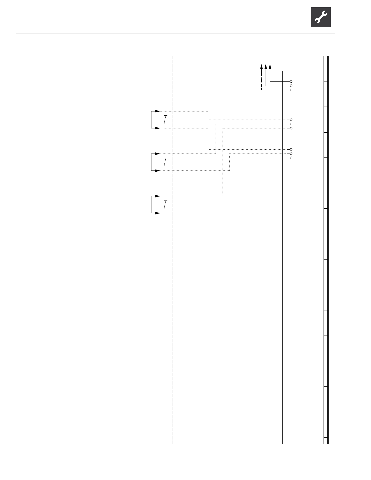
49
Subject to change without notice | 83053700gUK – Translation into English of the original German operating manual | ait-deutschland GmbH
L
/2.15N/2.15PE/2.15
L
-X0
N PE L
-X0
L L
MOT
-X2.
ASD
EVU
K10
MOT Connection of external motor protection; bridge if no external motor protection is connected.
UK817379a
Controller board; Attention: I-max = 6A/230VAC
ASD
Function
EVU
External flow rate switch; bridge if no switch is connected.
Legend:
-K10
MOT
Operating materials
ASD
Energy supplier contact; closed on release; bridge if no blocking intervalEVU
1 2 3 4 5 6 7 8 9 10 11 12 13 14 15
Circuit diagram 3/3 SWP 371 / SWP 451
Page 50
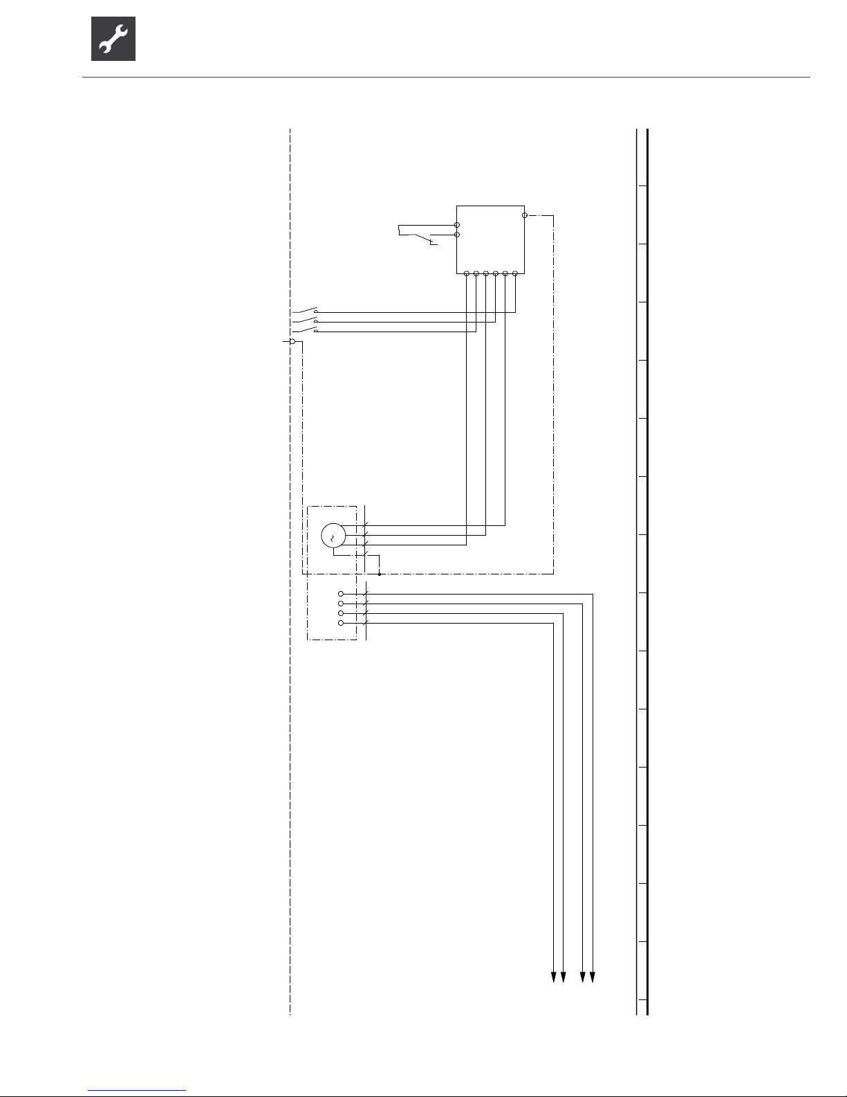
50
Subject to change without notice | 83053700gUK – Translation into English of the original German operating manual | ait-deutschland GmbH
PE
IN 0V
L1UL2VL3
W
-Q11
14 12
11
-K1
/2.4
1
2
-Q0
/2.5
3
4
5
6
PE
-X10
M
3
T1 T2 T3 PE
-M1
VD1
T1
-230V
T2 M1
-F1.1
M2
L Reg
/2.1N/2.1
HDP
/2.1
MOT
/2.1
L3L2L1
F1.1 Compressor motor protection
42
PE
Legend:
UK817380a
Q11
2
Starting current limit compressor
Q0
VD1
-M1
compressor
Mains contactor, compressor
3~PE/400V/50Hz
K1
M1
Function
Sump heating for compressor 1
13
Terminal in switch box heat pump
3
L1,L2,L3,PE; power supply, output, compressor; clockwise rotary field is absolutely necessary!
Operating materials
3~PE/400V/50Hz
1
X10
VD1
auxiliary relay compressor
E20
1 2 3 4 5 6 7 8 9 10 11 12 13 14 15
SWP 581 / SWP 691 / SWP 561H Circuit diagram 1/3
Page 51
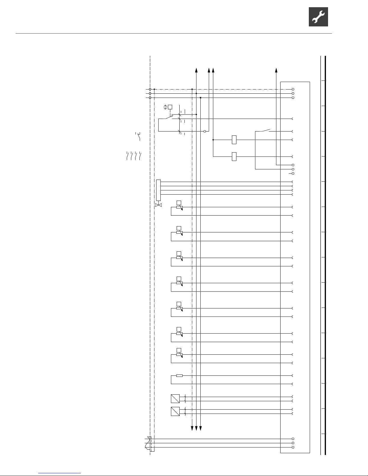
51
Subject to change without notice | 83053700gUK – Translation into English of the original German operating manual | ait-deutschland GmbH
L Reg
/1.15
MOT
/1.15
HDP
/1.15
N
/1.15,15
PE
-X1
PE
-X10
N
N
L
L
P
+-
b2 c4
a1
-F1
HDP
DI1
-X2
DI2
13
14
-Q0
5
1
-X10
OUT1
A1
A2
-K1
OUT5
A1
A2
-Q0
L..
-X4
L..
L..
B/
-X6
A
Green
Yellow
white
Brown
-K22
A/ B
ϑ
NT1
-X7
-R1
TSG1
GND
ϑ
NT3
-R3
TWE
GND
ϑ
NT4
-R4
THG
GND
ϑ
NT5
-R5
TSG2
GND
ϑ
NT6
-R6
TVL
GND
ϑ
NT7
-R7
TRL
GND
ϑ
NT8
-R8
TWA
GND
NT9
-R9
CW
GND
GND
-X8
I
P
12
-B10
HD
AIN1
GND
I
P
12
-B11
ND
AIN2
L
/3.1N1,/3.1PE/3.1
3
-X11
2
321
PE
1
12
/1.4
34
/1.4
56
/1.4
13 14
4
12
14
11
/1.2
4321
1
TWA
TVL
Terminal in switch box heat pump
-K20
2
X10
2
K20
Hot gas sensor
1
Function
THG
HD
TRL
auxiliary relay compressor
Mains contactor, compressor
GND/LIN/12V
High-pressure sensor
R6
TSG2
R4
K1
F1
1~N/PE/230V/50Hz
High-pressure switchR2Electronic expansion valve
2
1~N/PE/230V/50Hz
VD1
3
TSG1
230VAC
rt
-F1
Suction sensor, evaporator
Controller board; Attention: I-max = 6A/230VAC
Suction sensor, compressor
B10
Legend:
1
Low pressure sensor
R9 CW Coder resistance; S58-69KW 11,5kOhm / S29-56KW 12,1kOhm
TVD Sump heating sensor
TWE
Flow sensor
R5
K22
Return sensor
B11
R7
R1
HDP
Q0
Operating materials
R3
Heat source output sensorR8
s
w
UK817380a
ND
L,N,PE; power supply, controller
Heat source input sensor
b
l
1 2 3 4 5 6 7 8 9 10 11 12 13 14 15 16
Circuit diagram 2/3 SWP 581 / SWP 691 / SWP 561H
Page 52
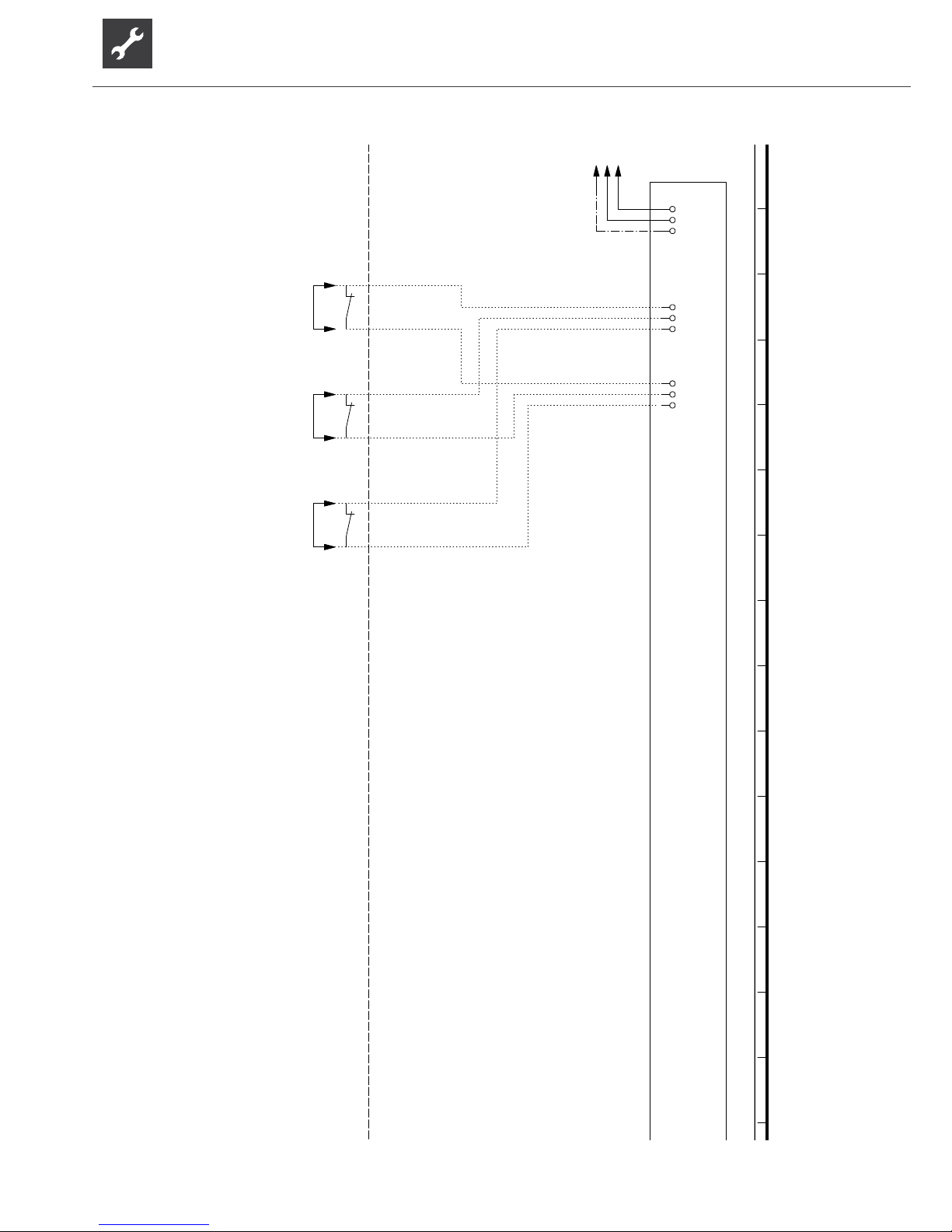
52
Subject to change without notice | 83053700gUK – Translation into English of the original German operating manual | ait-deutschland GmbH
L
/2.15N/2.15PE/2.15
L
-X0
N PE L
-X0
L L
MOT
-X2.
ASD
EVU
-K10
MOT
External flow rate switch; bridge if no switch is connected.
Legend:
Energy supplier contact; closed on release; bridge if no blocking intervalEVU
Operating materials
ASD
K10 Controller board; Attention: I-max = 6A/230VAC
MOT
UK817380a
EVU
Connection of external motor protection; bridge if no external motor protection is connected.
ASD
Function
1 2 3 4 5 6 7 8 9 10 11 12 13 14 15
SWP 581 / SWP 691 / SWP 561H Circuit diagram 3/3
Page 53
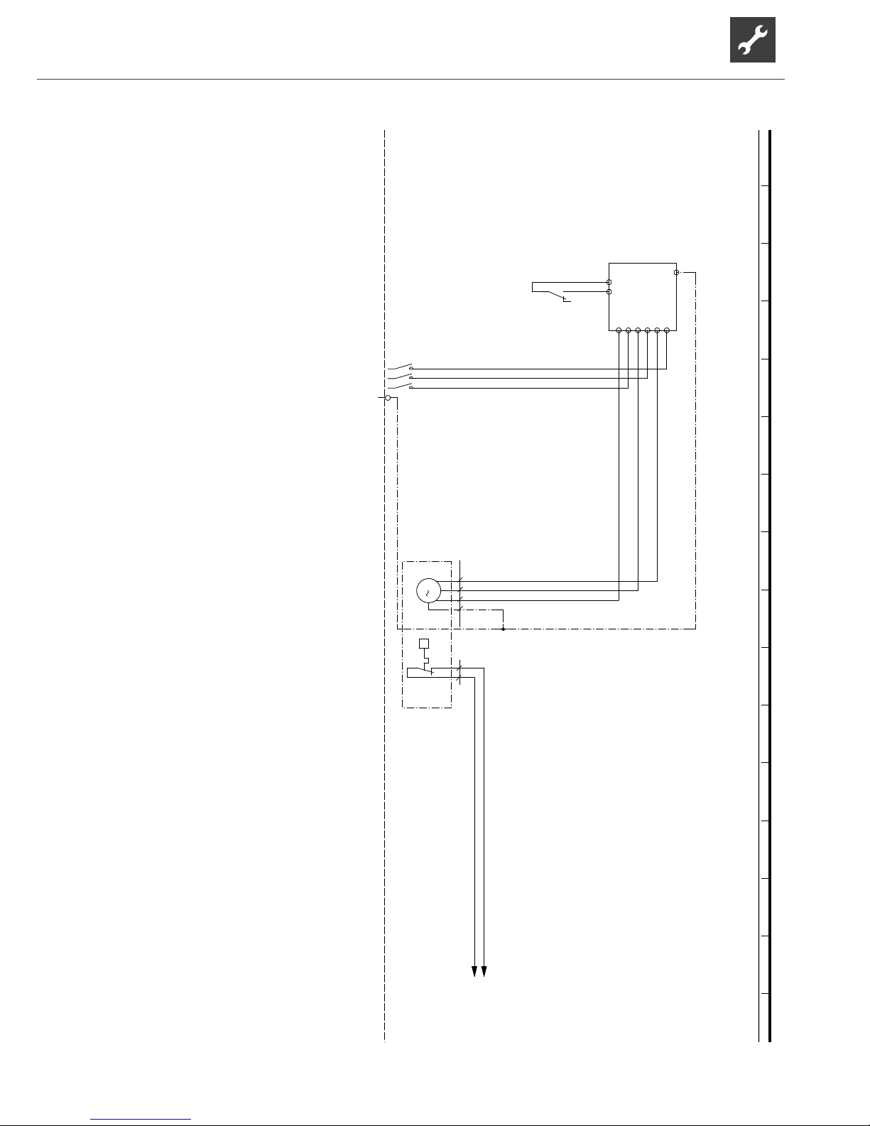
53
Subject to change without notice | 83053700gUK – Translation into English of the original German operating manual | ait-deutschland GmbH
PE
IN 0V
L1UL2VL3
W
-Q11
14 12
11
-K1
/2.4
1
2
-Q0
/2.4
3
4
5
6
PE
-X10
M
3
T1
T2
T3
PE
-M1
VD1
ϑ
-F2
MOT
/2.1
L-Steu
/2.1
1
L1,L2,L3,PE; power supply, output, compressor; clockwise rotary field is absolutely necessary!
L1
Compressor motor protection
Function
UK817385b
Starting current limit compressor
L2
X10
13
3~PE/400V/50Hz
M1
auxiliaire compresseur
L3
F2
K1
Terminal in switch box heat pump
PE
2
2
VD1
Operating materials
Mains contactor, compressor
-M1
3~PE/400V/50HzQ0Legend:
VD1
Q11
compressor
1 2 3 4 5 6 7 8 9 10 11 12 13 14 15 16
Circuit diagram 1/3 SWP 291H
Page 54
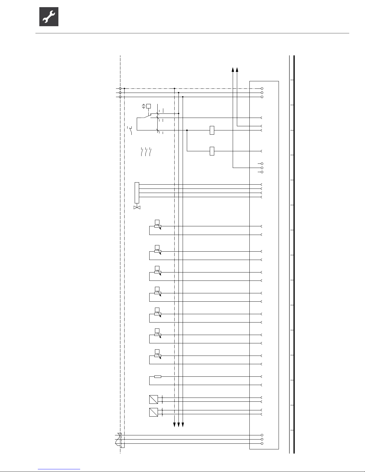
54
Subject to change without notice | 83053700gUK – Translation into English of the original German operating manual | ait-deutschland GmbH
MOT
/1.15
L-Steu
/1.15
PE
-X1
PE
-X10
N
N
L
L
P
+-
b2 c4
a1
-F1
HDP
DI1
-X2
DI2
OUT1
A1
A2
-K1
OUT5
A1
A2
-Q0
L..
-X4
L..
L..
B/
-X6
A
Green
Yellow
white
Brown
-K22
A/ B
ϑ
NT1
-X7
-R1
TSG1
GND
ϑ
NT3
-R3
TWE
GND
ϑ
NT4
-R4
THG
GND
ϑ
NT5
-R5
TSG2
GND
ϑ
NT6
-R6
TVL
GND
ϑ
NT7
-R7
TRL
GND
ϑ
NT8
-R8
TWA
GND
NT9
-R9
CW
GND
GND
-X8
I
P
12
-B10
HD
AIN1
GND
I
P
12
-B11
ND
AIN2
L
/3.1N/3.1PE/3.1
3
-X11
2
321
PE
1
12
/1.5
34
/1.5
56
/1.5
12
14
11
/1.3
UK817385b
TWE
Q0
2
TSG2
High-pressure switch
TSG1
TRL
auxiliaire compresseur
R8
B10 HD
Controller board; Attention: I-max = 6A/230VAC
230VAC
3
VD1
Hot gas sensor
R1
Coder resistance; 18, 7 kOhm
-F1
K1
GND/LIN/12V
Legend:R41~N/PE/230V/50Hz
High-pressure sensor
K22
HDP
R9
K20
1~N/PE/230V/50Hz
rt
F1
-K20
Heat source output sensor
Low pressure sensor
THG
1
TVL
s
w
Heat source input sensor
21
R5
4123
X10
TWA
CW
Terminal in switch box heat pump
Electronic expansion valve
Function
2
R3
Suction sensor, evaporator
R7
L,N,PE; power supply, controller
ND
Return sensor
B11
Mains contactor, compressor
Suction sensor, compressor
b
l
R6
1
Operating materials
Flow sensor
1 2 3 4 5 6 7 8 9 10 11 12 13 14 15 16
SWP 291H Circuit diagram 2/3
Page 55
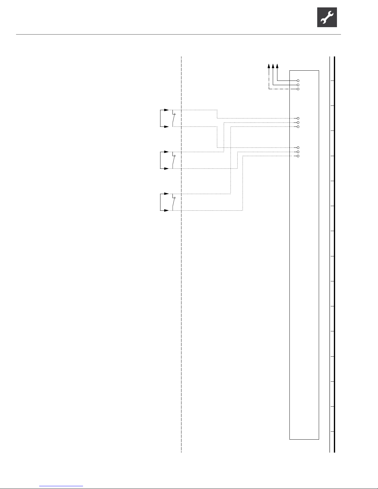
55
Subject to change without notice | 83053700gUK – Translation into English of the original German operating manual | ait-deutschland GmbH
L
/2.15N/2.15PE/2.15
L
-X0
N PE L
-X0
L L
MOT
-X2.
ASD
EVU
-K10
MOT
External flow rate switch; bridge if no switch is connected.
Legend:
Energy supplier contact; closed on release; bridge if no blocking intervalEVU
Operating materials
ASD
Connection of external motor protection; bridge if no external motor protection is connected.
UK817385b
K10
MOT
Function
EVU
Controller board; Attention: I-max = 6A/230VAC
ASD
1 2 3 4 5 6 7 8 9 10 11 12 13 14 15 16
Circuit diagram 3/3 SWP 291H
Page 56

56
Subject to change without notice | 83053700gUK – Translation into English of the original German operating manual | ait-deutschland GmbH
Page 57

57
Subject to change without notice | 83053700gUK – Translation into English of the original German operating manual | ait-deutschland GmbH
Page 58

58
Subject to change without notice | 83053700gUK – Translation into English of the original German operating manual | ait-deutschland GmbH
Page 59

59
Subject to change without notice | 83053700gUK – Translation into English of the original German operating manual | ait-deutschland GmbH
II
A1
ait-deutschland GmbH
Industrie Str. 3
95359 Kasendorf
Germany
Unit model
100 615
SWP 371 *
SWP 451 *
SWP 581 *
SWP 691 *
SWP 291H *
SWP 561H *
EC Directives
Standardized EN
EN 349
EN 60529
Designated position:
TÜV-SÜD
Industrie Service GmbH (Nr.:0036)
EN 60335-1/-2-40
EN ISO 13857
EN 61000-3-2/-3-3
Module
UK818163c
EN ISO 12100-1/2
EN 55014-1/-2
EN 378
* Pressure equipment component
Kasendorf, 14.12.2015
Company:
Place, date:
Signature:
Category
2011/65/EG
Designation of the device(s)
Number
Unit model
Number
confirms that the following designated device(s) as designed and marketed by us fulfill the
standardized EC directives, the EC safety standards and the product-specific EC standards.
In the event of modification of the device(s) without our approval, this declaration shall become
invalid.
The undersigned
Heat Pump
100 614
100 616
100 617
100 618
100 619
EC Declaration of Conformity
in accordance with
the EC Machinery Directive 2006/42/EC, Annex II A
2006/42/EG
2009/125/EG
2006/95/EG
2010/30/EU
2004/108/EG
*97/23/EG
Jesper Stannow
Head of Heating Development
Page 60

ait-deutschland GmbH
Industriestraße 3
D-95359 Kasendorf
E [email protected]
W www.alpha-innotec.de
alpha innotec – an ait-deutschland GmbH brand
UK
 Loading...