

Page 1
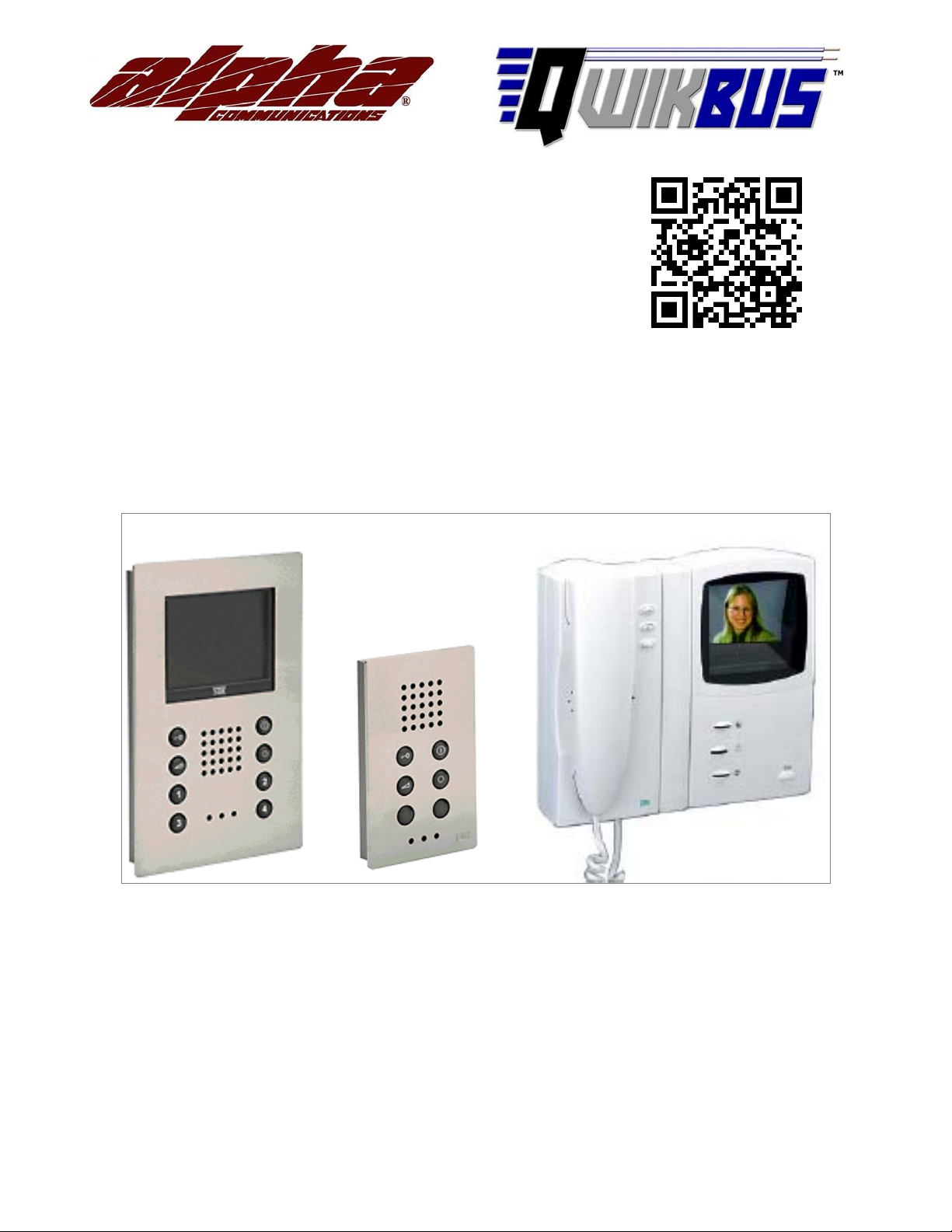
STR QwikBus™
2wireColorVideo
Intercom System
(with TT33-3, VSP333-3 and KBS3-2)
Installation, Programming, and
User’s Manual
Copyright© 2013-2015, Alpha Communications®, All Rights Reserved
Rev. 2.2 - 11/2015
AWD184
Page 2

STR QwikBus™ 2 wire Color Video Intercom System
Introduction
Compatible Inside Stations
Planning the Installation
Wiring Diagrams
Single Entry STR Modular Panel
Multiple Entry STR Modular Panels
Single Entry Custom Panel
Multiple Entry Custom Panels
Important Notes on Monitor Riser Connections
EVB33 Distribution Units
Dipswitch Settings
System Camera Options – Lobby Panels, and Observation
End of Line Resistors Jumper Locations
The Matrix – Wiring Custom Panel Buttons to the TT33-3
E32 Matrix Extenders
1
1
2
4
5
6
7
8
9
10
11
12
13
13
The IC2 database chip
Opening and Closing the VFS1500/1000 VH3033 Inside Stations
Programming the QwikBus™ System -- Open Voice (VFS1500/1000)
Programming (on site)
Programming Inside Stations for parallel operation
One Man Bench Programming
Programming VFS1500 stations for Intercommunication
Programming the QwikBus™ System --Handset (VHC3033-2)
Programming (on site)
Programming Inside Stations for parallel operation
One Man Bench Programming
USER Operation
14
14
15
15
15
16
17
18
18
18
19
VHC3033-2 Color Handset
VFS1500/ VFS1000 Monitors & FS1500/FS1000 Audio Stations
b
20
21
Page 3
The STR QwikBus™ takes advantage of the latest in digital technology to provide a high tech,
p
high quality color video intercom system operating on a 2 common wire BUS.
QwikBus™ video monitor stations all feature a crystal clear 4" LCD Color screen (measured
diagonally) and can be surface or flush mounted (with optional UMV1000 flush housing). You
can choose from the VFS1000 series (hands free VOX without internal communications) or
the VFS1500 series hands free VOX (with internal communications for up to 5 units per apt.),
as well as handset style monitors and audio only stations all on the same 2 twisted wires.
Audio only stations are available as well and can be mixed and matched to suit your
particular application.
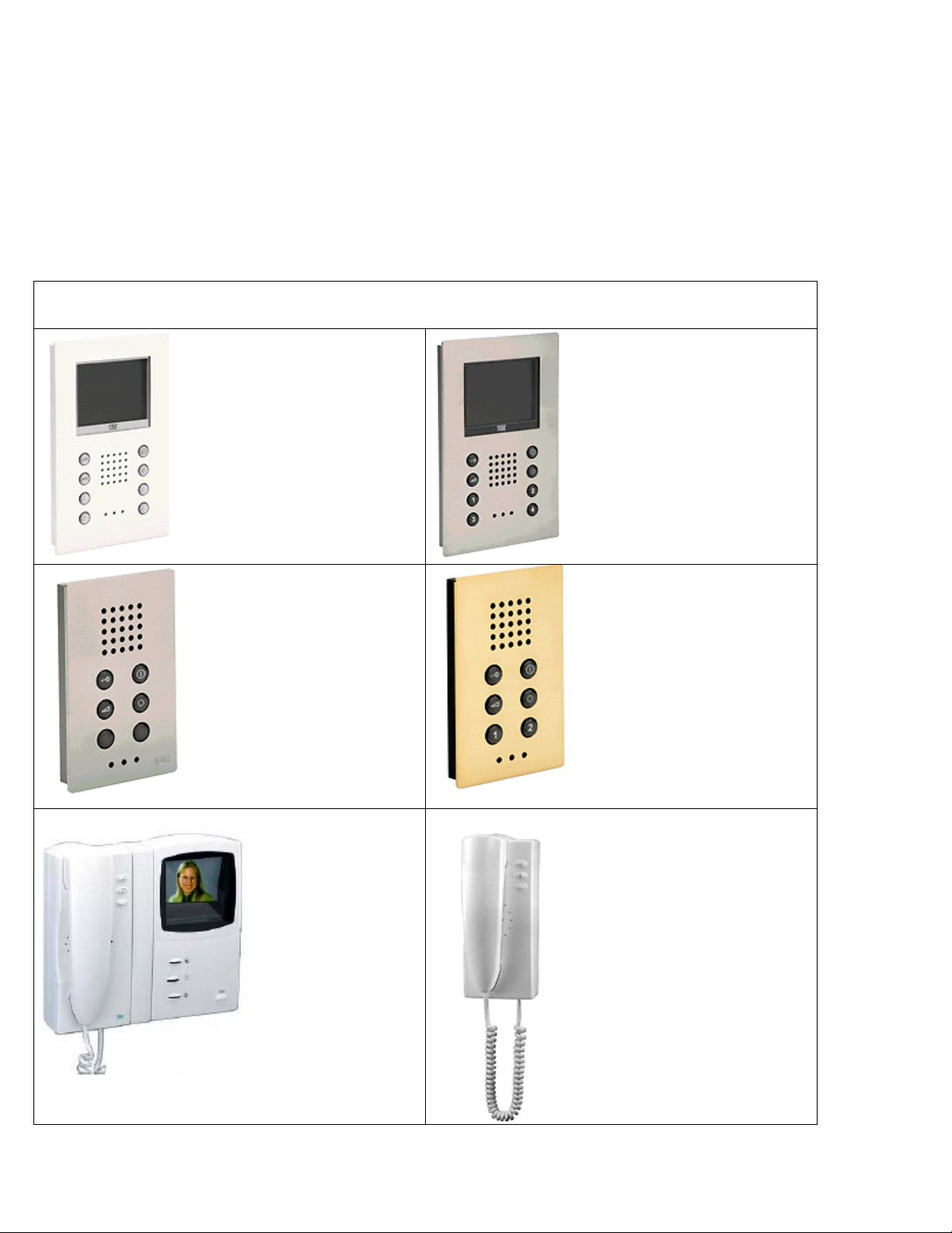
QwikBUS™ COMPATIBLE INSIDE STATIONS
VFS1000
COLOR MONITOR
Voice Operated hands free
Available in 6 Designer
Finishes
FS1000 SERIES
AUDIO STATION
Voice Operated Hands free
Available in 6 Designer
Finishes
Crystal Clear Sound
VFS1500
COLOR MONITOR
Voice Operated hands free
Available in 6 Designer
Finishes
Communicate internally
between up to 5 stations per
a
artment.
FS1500 SERIES
AUDIO STATION
Voice Operated Hands free
Available in 6 Designer
Finishes
Crystal Clear Sound
Internal Communications
Capable
VHC3033-2
COLOR
HT3033
AUDIO HANDSET
MONITOR
W/HANDSET
Available in White,
Available in White,
Titanium, and
Anthracite
1
Titanium, and Anthracite
Page 4

PLANNING THE INSTALLATION
Is this a COLOR Video installation?
This manual is written expressly for the QwikBus™ 2-wire Color systems that will be
using the Inside monitors listed on the previous page. If you are installing a Black and White
system, please refer to the QwikBus™ 4-wire Black & White Manual.
How many apartments?
QwikBus™ can run up to 120 apartments and can exceed that number if specially
designed. If you will be installing a larger system please contact Alpha Communications® for
assistance.
How many apartments will need more than 1 monitor?
An apartment can have up to 4 monitors and or audio stations that will ring when the
entry button is pressed. A fifth can be added a custom TT33-8P as opposed to the standard
TT33-3.
Will these multiple monitor apartments need intercommunication?
Intercommunication is only available using the VFS1500/ FS1500 series stations which
allow you to ring 2-4 other stations in the apartment depending on the equipment used.
How many Entrances?
Typically,QwikBus™canhaveupto8Entrance panels. If you will be installing a larger
number of entrances please contact Alpha Communications® for design assistance.
Modular Panel?
STR™ modular panels are available in White, Titanium, and Dark Brown and areusually
used in small installations from a 1 button residential application up to multi-apartment
configurations and feature beautiful contemporary looks, illuminated buttons, and outside
weather resistance.
Stainless Steel or Brass Panel?
Alpha Communications® can custom design and build flush and surface mount entry
panels in Stainless Steel or Polished Brass with all necessary apartment button numbering
and address engraving.
How many observation cameras will be in the system?
Additional Cameras can be added in addition to the Entrance Cameras for a total of 8,
enabling the apartment monitors to view the various feeds on demand.
What type of Inside stations will you use?
Although all the compatible stations connect the same way, each model does have
certain capabilities and advantages depending on the needs of the tenant and can be
exchanged for another unit at anytime if necessary by simply installing the2wiresand
reprogramming the system to recognize the unit.
2
Page 5
Are you running new wire or using existing wire from a previous system?
A
Although digital systems are fairly forgiving in wiring requirements, they are still
susceptible to RFI from unusually strong nearby transmitters, EMI from electrical lines
running nearby, or existing wiring that is not twisted, in poor condition, or not a suitable gauge.
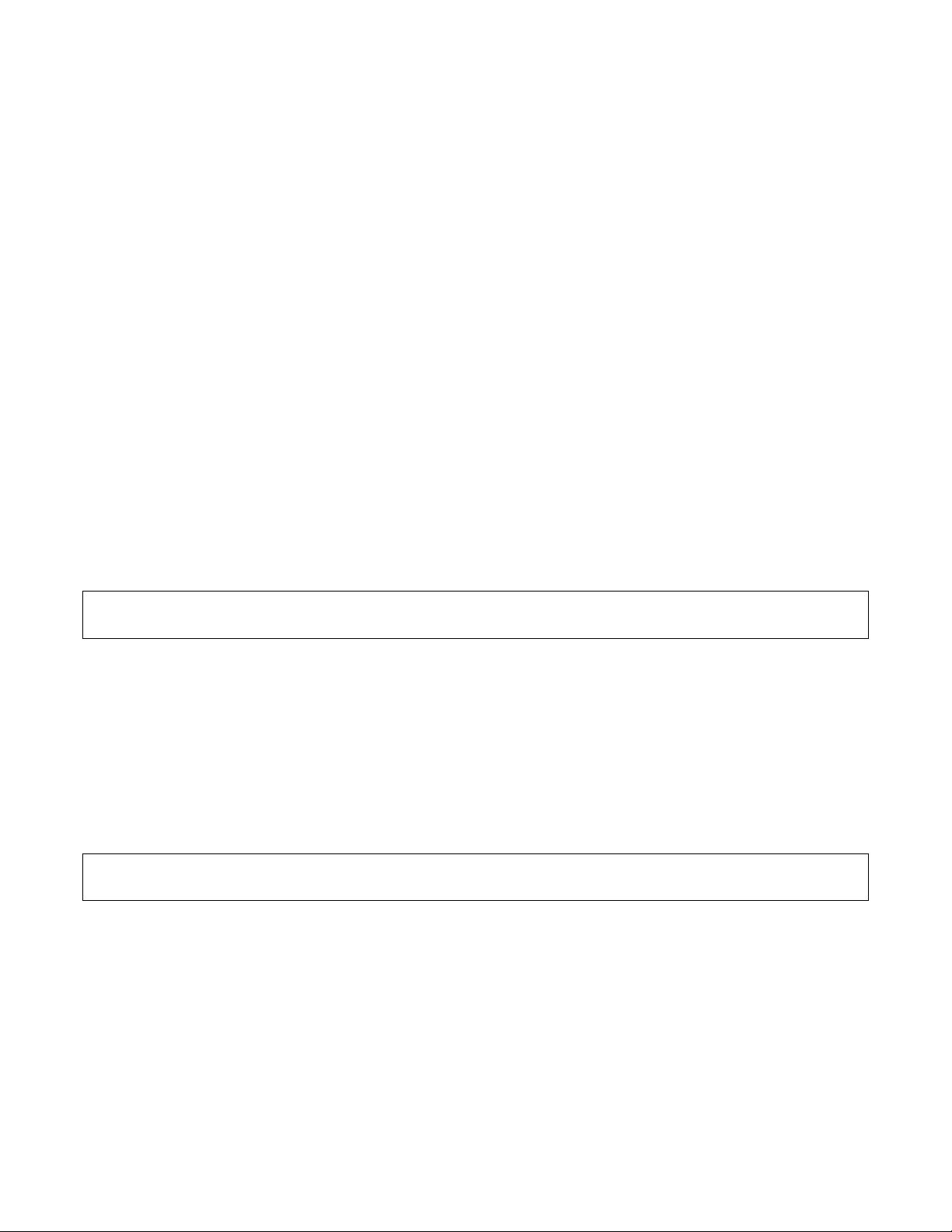
Please refer to the wiring thickness chart below to determine the minimum recommended
wire gauge needed. If the existing wiring is more than 12 years old, has deteriorating
insulation, questionable splice connections, corrosion, or is not configured as twisted pair
wiring, it is highly recommended that new wire be run.
To reduce the risk of interference problems:
lwaysuseasingle twisted pairwire forthe two wire BUS line.
Do NOT double wires to increase effective wire diameter. This will cause interference
problems.
Do NOT install anyunused additional wires with open ends.
Neverconnect the shield from a cable, orconnect the shield from one cable to another.
Use a separate cable to the door strike from the SP333.
Onlyuse a 12VAC door strike or12VAC relaywith less than 1 amp draw.
If it is absolutelynecessaryto run the door strike wiringin the same cable as the BUS
line, you must use a transient voltage suppressor at the door strike end.
Loop resistance should be less than 20 ohms.
Twisted pair is always recommended.
Cat5, Cat5E, Cat6, and the new Cat7 spec. wire is NOT recommended.
How many risers will you be using?
The recommended maximum number of monitors on a riser is 8-10 with each riser
originating from the VSP333-3 Control Unit, including from the EVB333 Amplified Splitter(s) if
your system requires them.
For technical assistance and help determining equipment needed please call:
Alpha Communications® at (800) 666-4800 Monday – Friday 8:30- 5:00 pm
3
Page 6
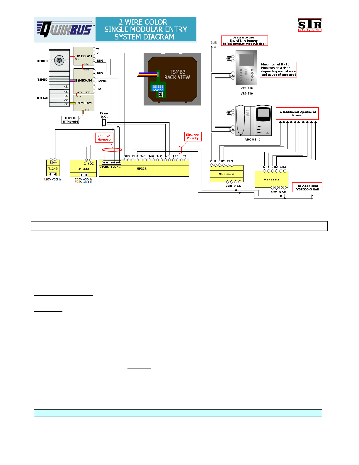
SystemNotes–2wireCOLORwithSingleModularEntry
If you require more than 3 VSP333-3 Units, please use MXV333 instead. Contact Alpha
Communications® for more information.
A Single Entry Modular system requires the following dipswitch settings on the back of the
TSMB3 unit:
Switches 4, 5, & 6
Switch 3
If the door strike is to be connected to the SP333 (Tö1) = OFF
identify the entrance number (all OFF = Entrance 1)
If the door strike is to be connected to the TSMB3 (Tö) = ON
For more information refer to Page 10 - Dipswitch Settings.
Be sure that the End of Line Jumpers are used on the camera circuit board and in the last
monitor on each riser. If the last unit on a riser is an audio only unit, the End of Line Jumper
would still be used on the last monitor
on that riser. This is important for best picture quality.
For more information refer to Page 12 - End of Line Jumper Locations.
When connecting C333-2 harness between SP333 and SNT333, ALWAYS observe 24VDC Polarity.
4
Page 7
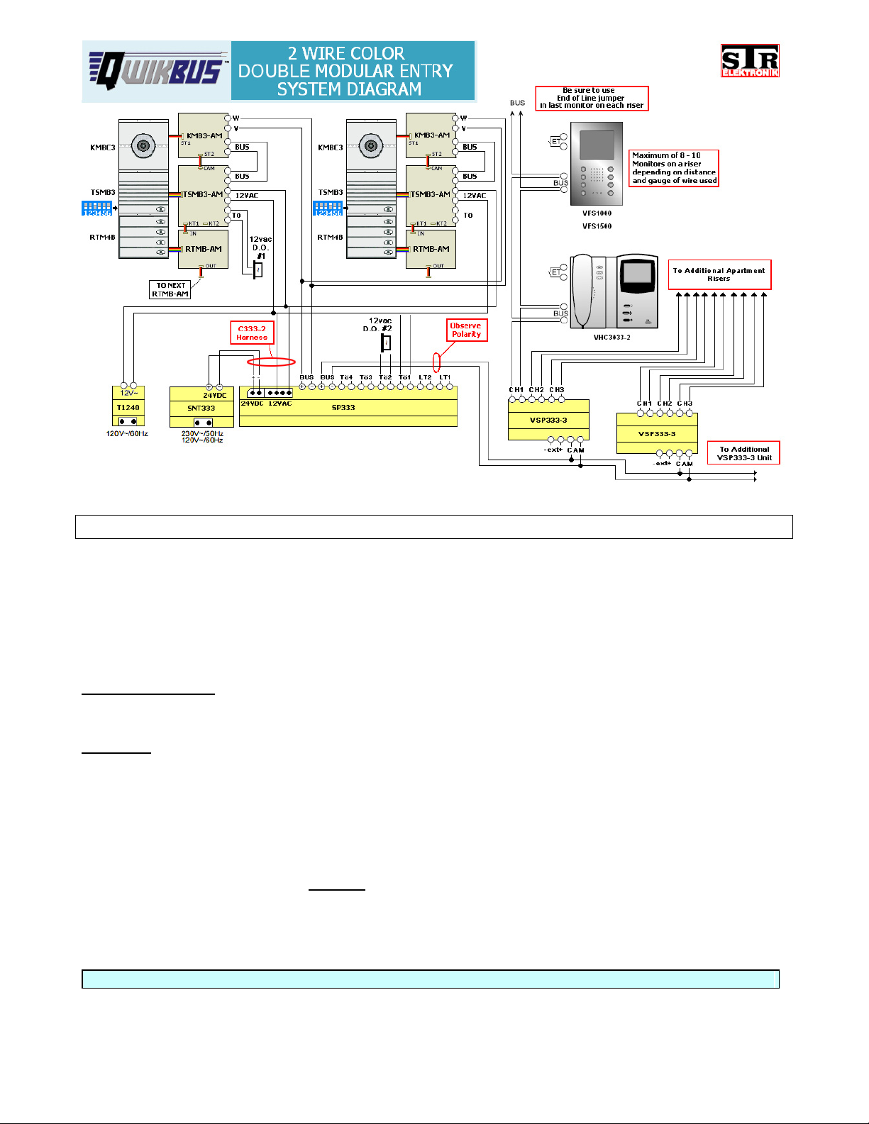
System Notes – 2 wire COLOR with Multiple Modular Entries
If you require more than 3 VSP333-3 Units, please use MXV333 instead. Contact Alpha
Communications® for more information.
Multiple Entry Modular systems require the following dipswitch settings on the back of the
TSMB3 unit:
Switches 4,5, &6 identify the entrance number. In the above example:
Entrance#1=4OFF/5OFF/6OFF Entrance#2=4ON/5OFF/6OFF
Switch 3 If the door strike is connected to the SP333 (Tö2) = OFF (as shown at Entrance 2)
If the door strike is connected to the TSMB3 (Tö) = ON (as shown at Entrance 1)
For more information refer to Page 10 - Dipswitch Settings.
Be sure that the End of Line Jumpers are used on the camera circuit board and in the last
monitor on each riser. If the last unit on a riser is an audio only unit, the End of Line Jumper
would still be used on the last monitor
on that riser. This is important for best picture quality.
For more information refer to Page 12 - End of Line Jumper Locations.
When connecting C333-2 harness between SP333 and SNT333, ALWAYS observe 24VDC Polarity.
5
Page 8
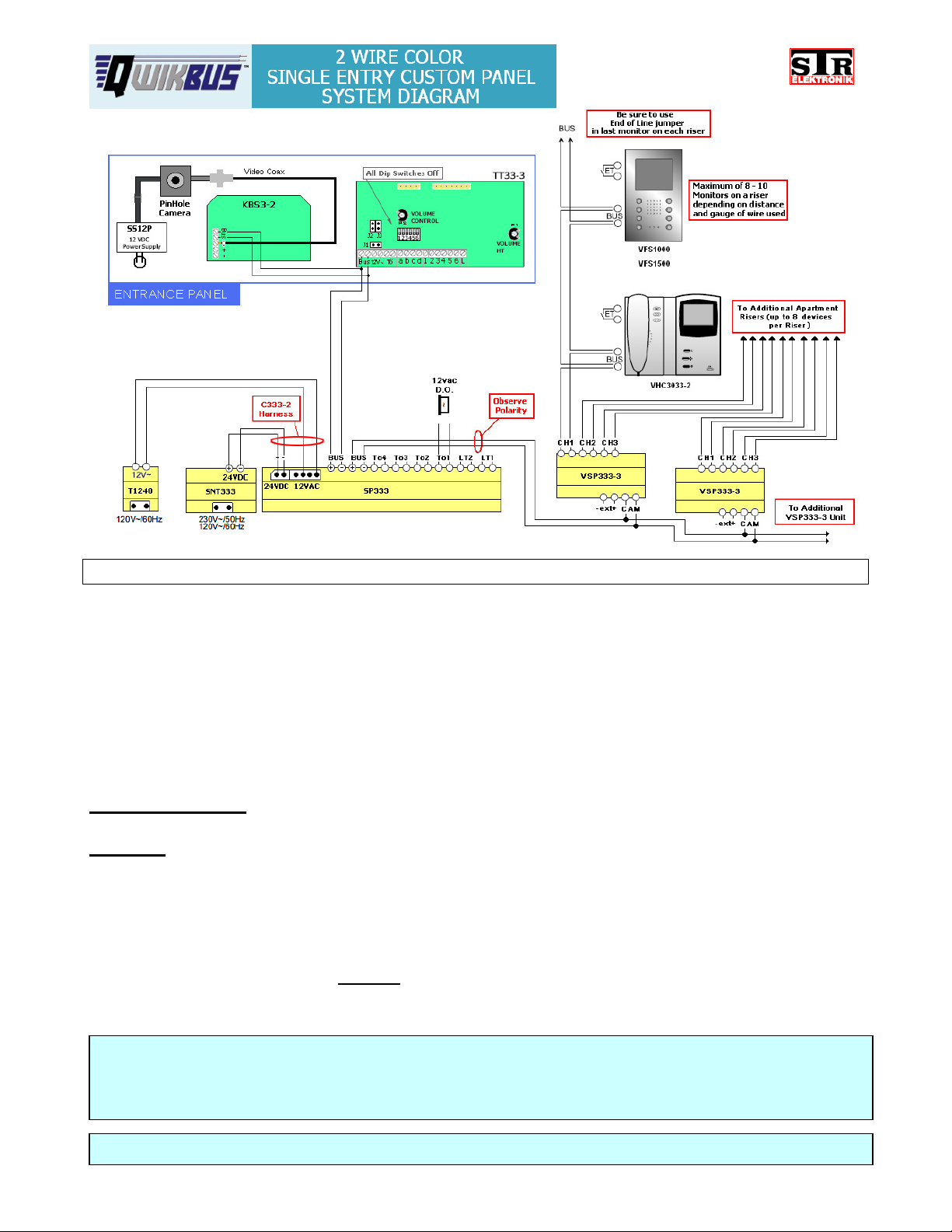
System Notes – 2 wire COLOR with Single Custom Panel Entry
If you require more than 3 VSP333-3 Units, please use MXV333 instead. Contact Alpha
Communications® for more information.
The TT33-3 SPEAKER/MICROPHONE/ CONTROLLER allows you to use QwikBus™ witha
custom panel or existing dry contact type entry panel by converting the button presses to a
digital signal through an electronic matrix. This matrix is discussed in detail on Page 13.
A Single Panel Entry system requires the following dipswitch settings on the TT33-3 unit:
Switches 4, 5, & 6 identify the entrance number (all OFF = Entrance 1)
Switch 3
If the door strike is to be connected to the SP333 (Tö1) = OFF
For more information refer to Page 10 - Dipswitch Settings.
Be sure that the End of Line Jumpers are used on the camera circuit board and in the last
monitor on each riser. If the last unit on a riser is an audio only unit, the End of Line Jumper
would still be used on the last monitor
on that riser. This is important for best picture quality.
For more information refer to Page 12 - End of Line Jumper Locations.
NOTE: When using a Coaxial cable into a KBS3-2, ALWAYS connect a 75Ω (for RG-59) or
50 Ω (for RG-6) End-of-Line resistor between the coax center lead terminal and the (-)
terminal on the KBS3-2. Failure to do this may cause degradation of the video signal.
When connectingC333-2 harness between SP333 and SNT333,ALWAYS observe 24VDC Polarity.
6
Page 9
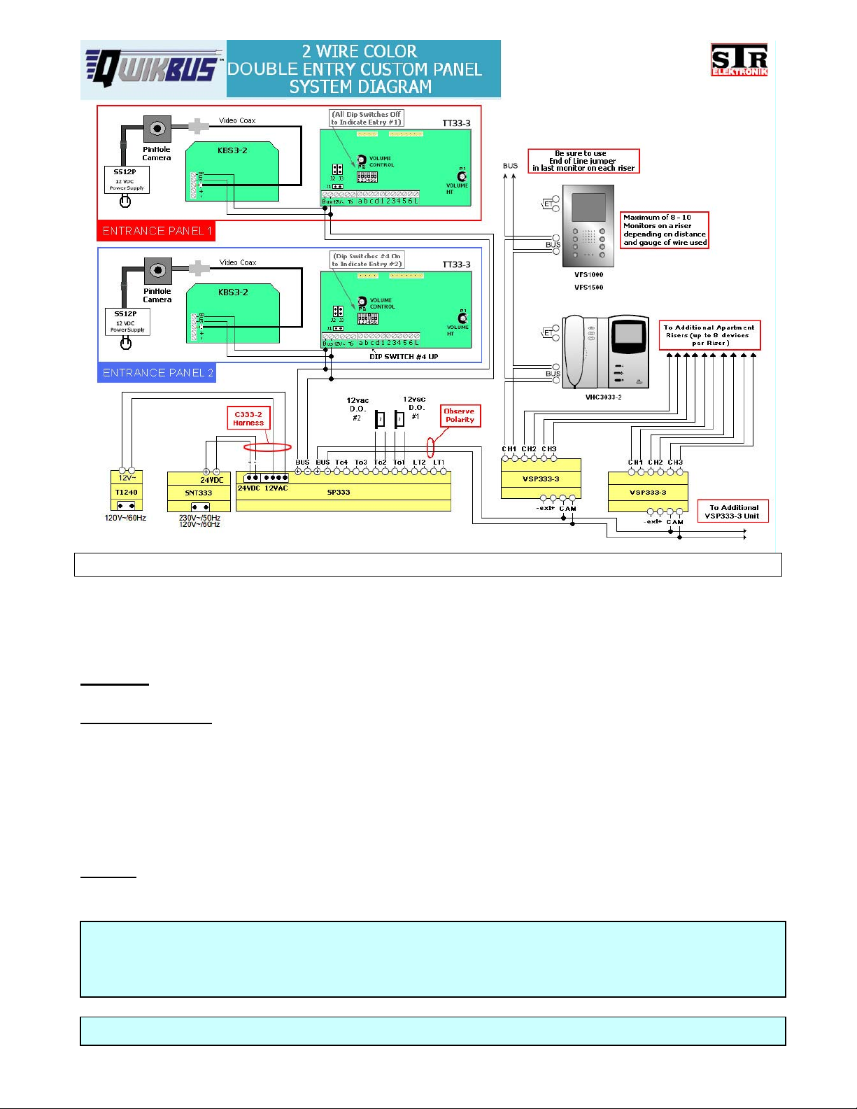
System Notes – 2 wire COLOR with Multiple Custom Panel Entries
If you require more than 3 VSP333-3 Units, please use MXV333 instead. Contact Alpha
Communications® for more information. Multiple Custom Panel Entry systems require the
following dipswitch settings on the back of the TT33-3 units:
Switch 3 If the door strike is connected to the SP333 (Tö2) = OFF (as shown at Entrance 2)
Switches 4,5, &6
Entrance#1=4OFF/5OFF/6OFF Entrance#2=4ON/5OFF/6OFF
Switches 4,5, &6 on the KMB3-2 should be set the same as the corresponding Entry.
For more information refer to Page 10 Dipswitch Settings. Be sure that the End of Line
Jumpers are used on the camera circuit board and in the last monitor on each riser. If the
last unit on a riser is an audio only unit, the End of Line Jumper would still be used on the last
monitor
Jumper Locations.
NOTE: When using a Coaxial cable into a KBS3-2, ALWAYS connect a 75Ω (for RG-59) or
50 Ω (for RG-6) End-of-Line resistor between the coax center lead terminal and the (
terminal on the KBS3-2. Failure to do this may cause degradation of the video signal.
When connectingC333-2 harness between SP333 and SNT333,ALWAYS observe 24VDC Polarity.
on that riser. This is important for best picture quality. (refer to Page 12) End of Line
identify the entrance number. In the above example:
-)
7
Page 10
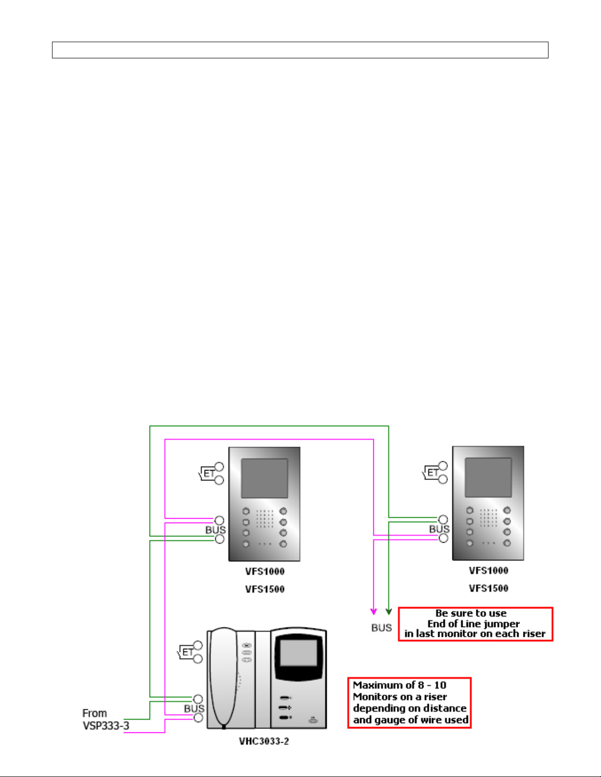
System Notes – 2 wire COLOR: Important Information on Monitor Riser Connections
This section discusses the proper procedure for connecting monitors on a riser.
Although a digital system is very forgiving, it is best to follow these rules during installation to
maximize performance and minimize potential problems.
Using existing wiring:
When using existing wiring there are many things that can cause problems. The first is
of course, wiring condition and gauge. Solid or stranded does not matter but a minimum of
18 gauge twisted shielded wire with the shield NOT connected together is strongly
recommended. Using any lighter gauge may result in loss of performance and/or
introduction of interference from outside power sources.
Many installers run the cable the easiest way and this, unfortunately, is usually by
running the wire in a conduit or small enclosure right along side AC power lines, near
fluorescent ballasts, or machinery. It is therefore suggested that you run your own wiring
for this job in the recommended way, and avoid wiring with unknown potential issues. If
this is not possible, it is best to advise the customer that the system may notworkuptoits
full potential especially with regard to video display.
Proper BUS Connections to the Monitors:
Although the polarity of the BUS connections on a monitor on a line is not important, it
is good form to reverse the connections from monitor to monitor on a BUS line to prevent
the propagation of signal distortion by putting them “out of phase” with each other. On the
picture below, note how the monitors are “reverse connected” as they go up a riser.
8
Page 11
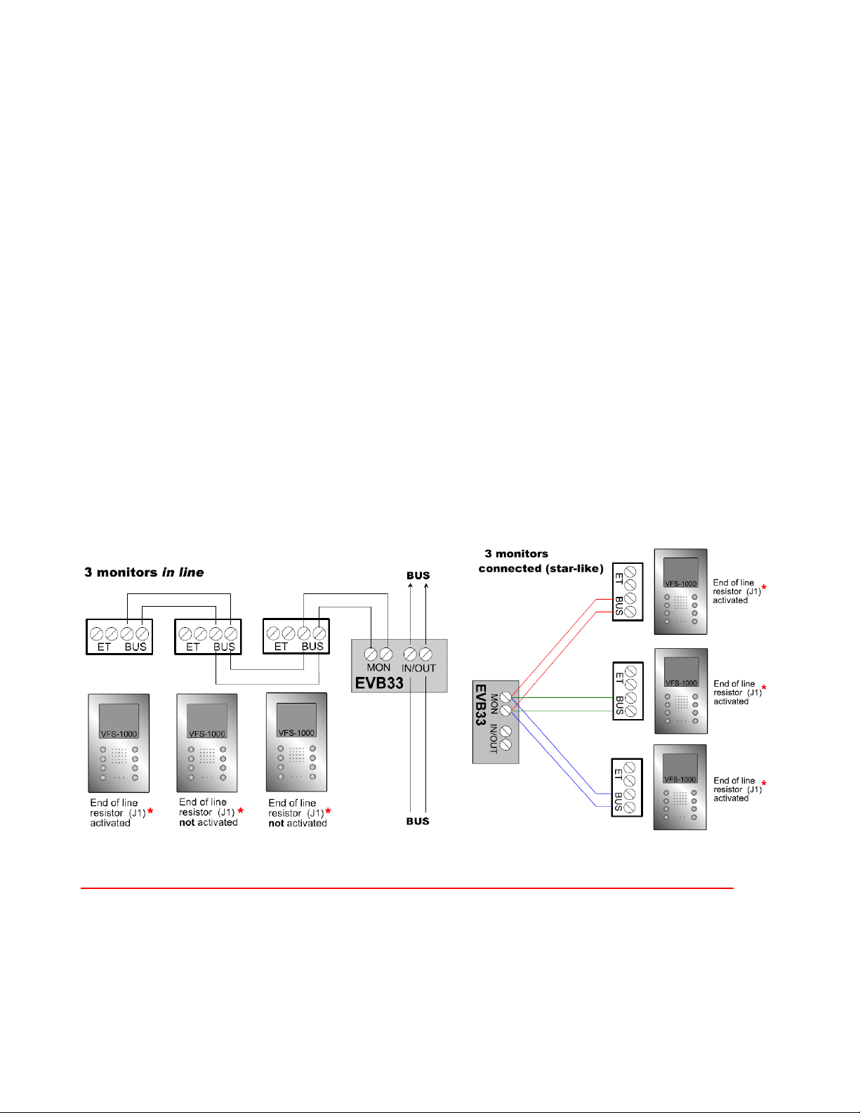
All Monitor BUS lines must be terminated with an End of Line resistor on the last
monitor in the run. This is built into each monitor and can be installed by putting a jumper
connector on J1
terminated properly, the electronic characteristics of the line will change resulting in signal
degradation and poor video quality.
Using EVB33 Distribution Units with BUS risers:
Always try to avoid branching or “T-Tapping” to connect monitors from a riser as this
will cause changes in the riser electronic characteristics which may cause signal
degradation and poor video quality. However, when it is necessary to “T-Tap” a line from
a BUS line, there are two important things to remember.
1. Use an EVB33 for each “T-Tap” to help minimize issues with signal propagation. This
can be done in an “in-line” method alternating polarity of the monitors, (maximum of 6
monitors or 8-10 monitors on the total riser) or in a “star” pattern with up to three monitors
on their own “sub” risers.
2.AlwaysusetheEndofLinejumper at the physical end of a riser line.
*. The location of this jumper is illustrated on Page 12. If a BUS is not
Both of these items are illustrated below.
* NOTE: End of line resistor (J1) may be labeled "Abschluss Widerstand" instead!
9
Page 12
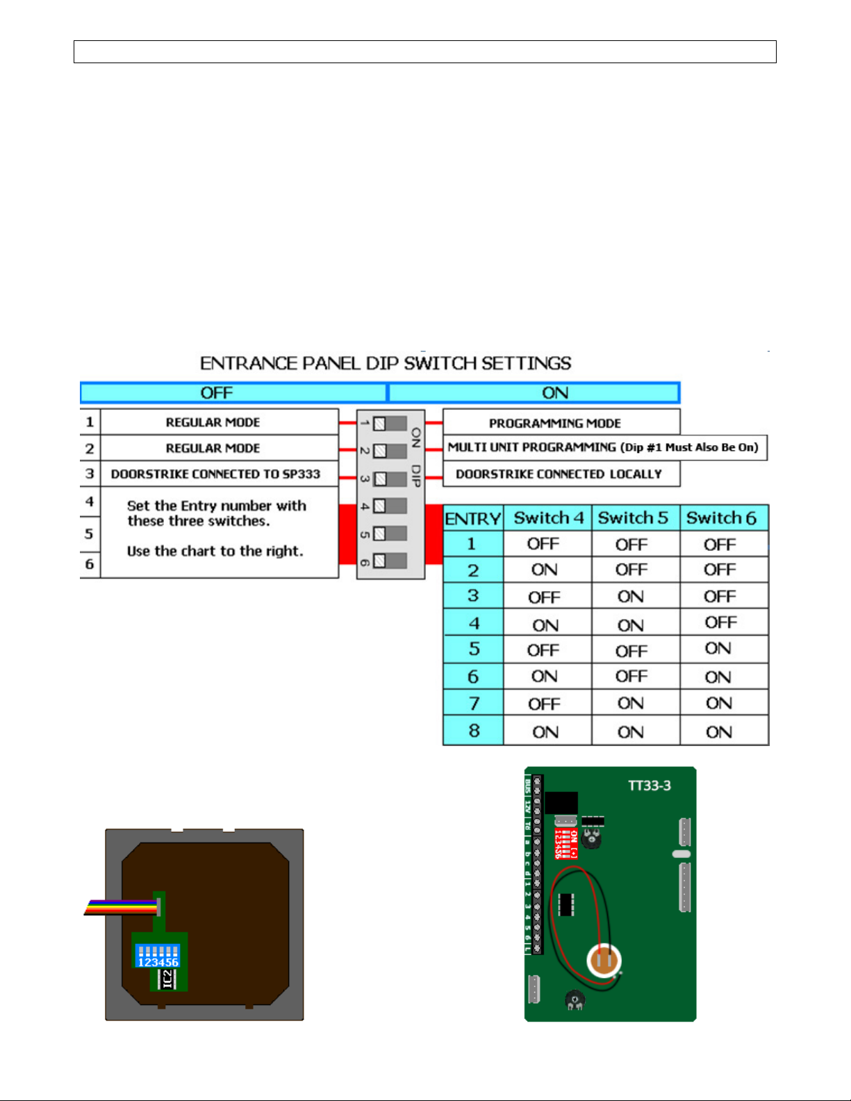
Dipswitch Settings – Entries & Door Strikes
The QwikBus™ system uses dipswitches for identification of Entry stations, additional
cameras, and to enter “Programming Mode”.
Entrance Panels must have a unique code so the system knows where the call is coming
from and which door to open. Dipswitches 4, 5, & 6 on the back of the Speaker/Microphone
Unit (TSMB3 (Modular style) or TT33-3 (Custom style)) assign this code as shown in the
chart below.
When a Door Strike is used, It can be connected locally to the TSMB3 (Modular style panels)
or TT33-3 (Custom style Panels) Tö terminals, or connected to the SP333 Controller at the
Tö1, Tö2, Tö3, or Tö4 terminals (number is related to the entry number). You must let the
system know which connection you will use by the position of the #3 dipswitch for each entry.
Dipswitch #3 = OFF (SP333)orON(TSMB3 or TT33-3). The entries DO NOT have to be set
alike.
TSMB3 Dipswitch Location TT33-3 Dipswitch Location
10
Page 13
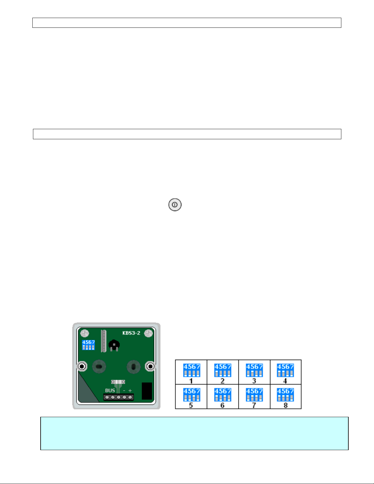
Entrance Panel Cameras
r
When using a Modular system, The Modular Camera (KMBC3*) is automatically identified by
being connected directly to the TT33-3 and takes the same Entrance number (1-8) of the
TT33-3.
When using a Custom Panel with a TT33-3 Speaker/Microphone/Controller, You can use
either a pinhole or CCTV type analog camera with it’s own power supply for system video
input. This camera will connect by coax to the KBS3-2 which is automatically identified by
being connected directly to the TT33-3 and takes the same Entrance number (1-8) of the
TT33-3 using dipswitches 4, 5 and 6.
Using analog cameras as add on observation cameras to the system.
You can add CCTV type cameras to the system that are not related to an entrance
panel to allow for observation of other areas using the KBS3-2.
As an example you could have 2 entries to the building using Camera #1 & #2, and use 3
observation cameras set as camera #3, #4, & #5. When a visitor rings from Entrance #1,
camera #1 will come on the monitor to display the visitor, but the resident can also cycle
through all five cameras by pressing the button.
When using any other camera(s) the KBS3-2 module must be used. This module has two
functions:
1. Converts the analog camera video signal to a digital signal that is used bythe
QwikBus™ system. The analog signal is fed into this module from any pinhole or
CCTV type camera by a standard RG59 or RG6 coax and sends the converted to
digital signal out through the BUS connections to the system.
2. Establishes a Camera numberforidentification. If this camera is addressed as # 2 fo
example, This KBS3-2 would be set to #2 using the dipswitches 4,5,&6 (7 is not used).
The 8 combinations are shown below.
NOTE: When using a Coaxial cable into a KBS3-2, ALWAYS connect a 75Ω (for RG-59) or
50 Ω (for RG-6) End-of-Line resistor between the coax center lead terminal and the (
terminal on the KBS3-2. Failure to do this may cause degradation of the video signal.
11
)
-
Page 14
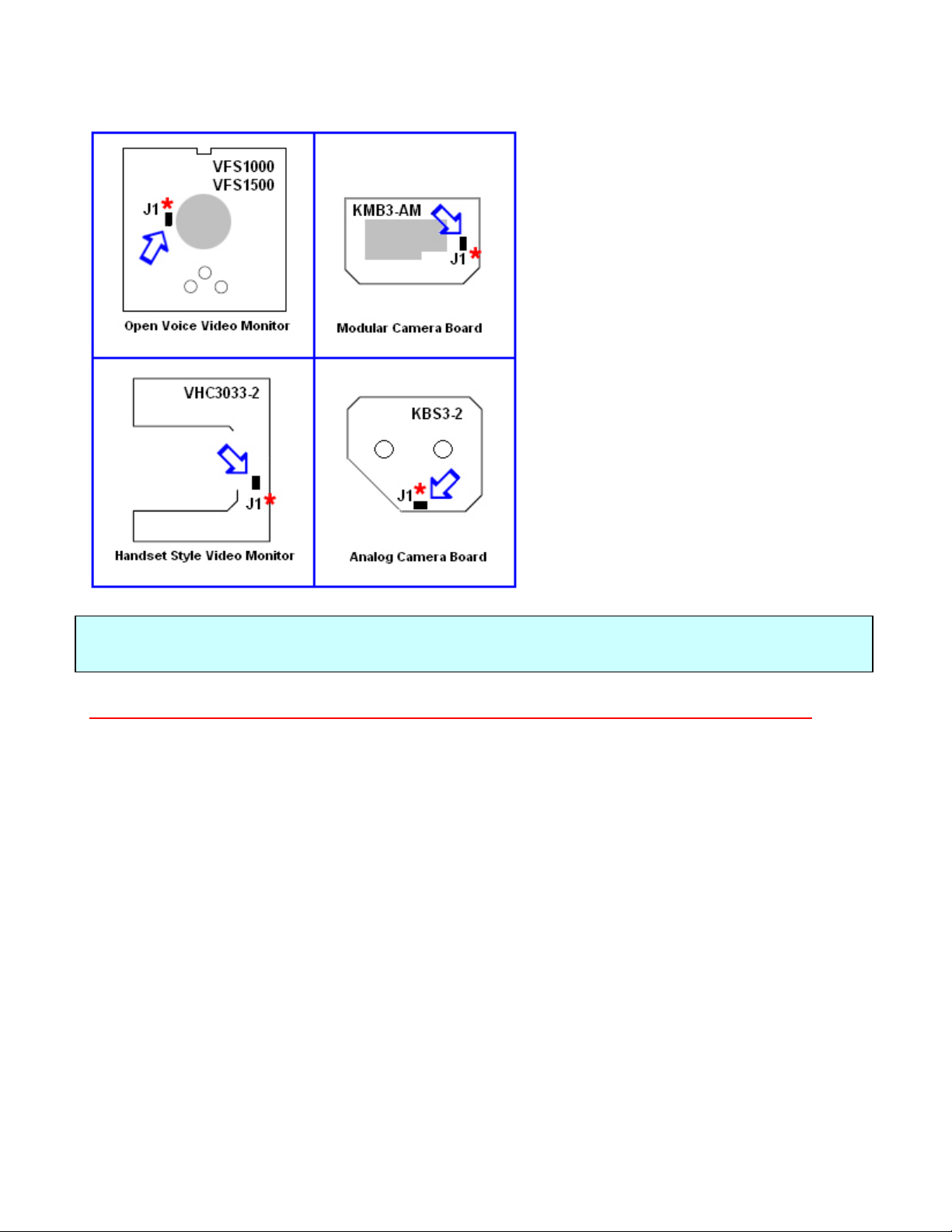
BUS End-of-Line Resistors – Jumper Locations
For proper system operation, the last video
monitor on a BUS riser as well as the last
camera on a run must have an End-of-Line
Resistors.
These resistors are built in to the printed
circuit boards and can be connected by
installing the jumper on the two pins labeled
J1*.
Usually these jumpers are supplied on all the
monitors and camera boards and must be
removed if the unit is not the last camera or
monitor connected to the BUS line.
If there is only one camera used or one
monitor used, the End-of-Line resistors must
still be used.
The Chart to the left shows the locations of
the J1*pins on the different circuit boards.
NOTE: Do not confuse this End-of-Line Resistor with the End-of Line resistor required at the
end of a coax cable entering the KBS3-2. See page 9 for more information.
* NOTE: End of line resistor (J1) may be labeled "Abschluss Widerstand" instead!
12
Page 15
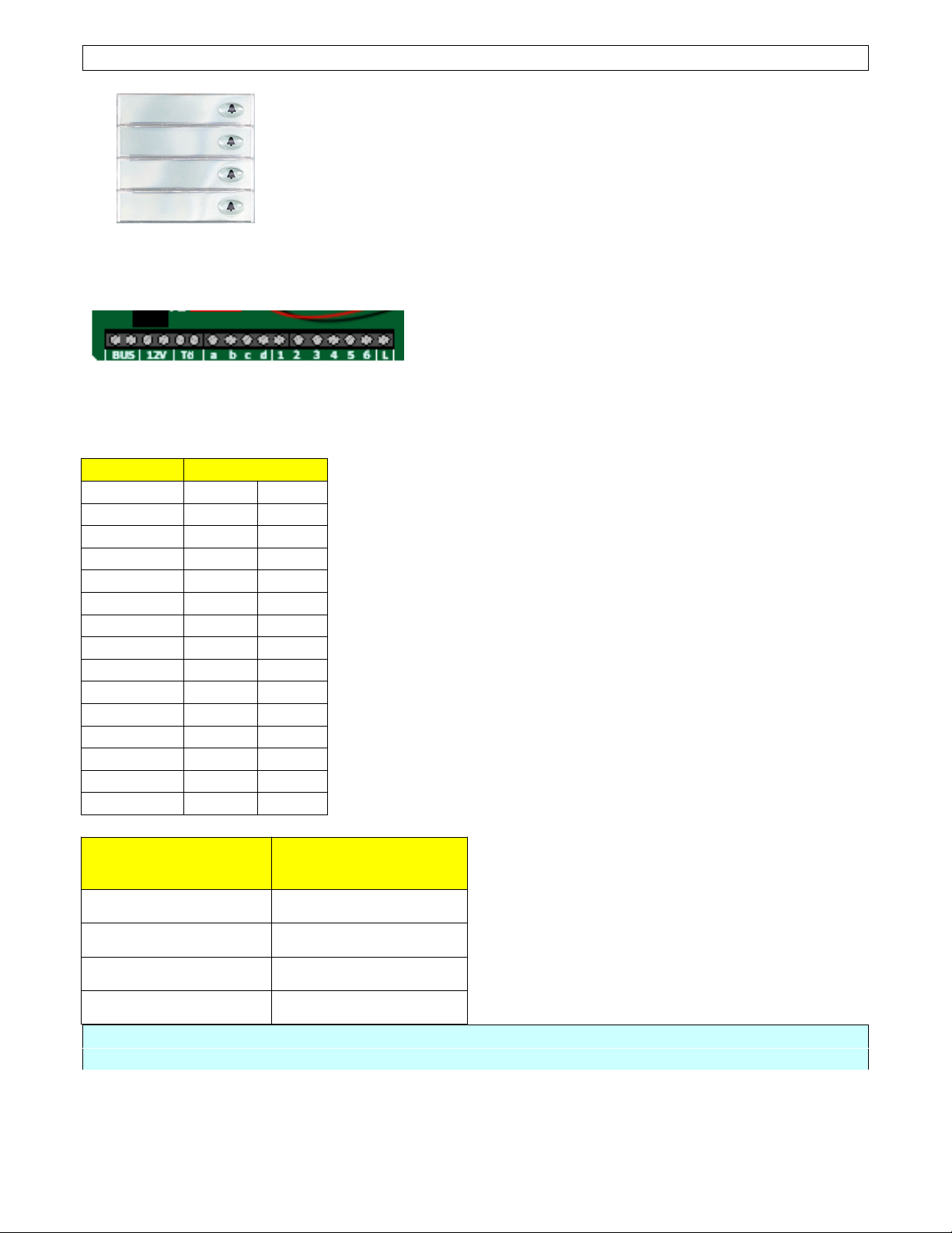
The Matrix – Wiring Pushbuttons to the TT33-3
A
A
A
A
A
When using an STR™ Modular Button assembly, the system can
read which switch is being pressed by electronics built into the
switches.
In the case of a Custom Panel, these electronics are built into the
TT33-3 and you must run wires to assign each button to a position
in a matrix.
Modular Button Assy.
Close up of TT33-3 Matrix Connections
The matrix consists of Common Connections
partment Connections
101
102 A 2
103
104
201 A 5
202
203 B 1
204 B 2
301 B 3
302 B 4
303 B 5
304 B 6
PH1 C 1
PH2 C 2
PH3 C 3
# of Apartments
1
3
4
6
Additional
Components
The chart to the left shows an example of how a 15 button
panel could be connected using combinations of letters and
numbers to give each button a unique identification in the
electronic matrix.
As long as each button is connected to a unique combination
of one letter and one number then the system will be able to
assign addresses to each button.
Using the matrix on the TT33-3 module, you can get 4x6 (24)
unique combinations. One of these combinations (DL) can be
used for special functions, so you can have up to a total of 23
or 24 apartments using the TT33-3 alone. If your system has
more apartments you may add the following parts (one for
each entry) which will extend the matrix by giving you more
numeric connections. Please refer to the chart below.
a,b,c,&d
and numbers 1 through 6.
1 – 23 or 24 ---
24 – 55 or 56 1 - E32
56 – 87 or 88 2 - E32
88 – 119 or 120 3 - E32
For systems larger than 120 apartments, contact Alpha Communications® for assistance.
13
Page 16
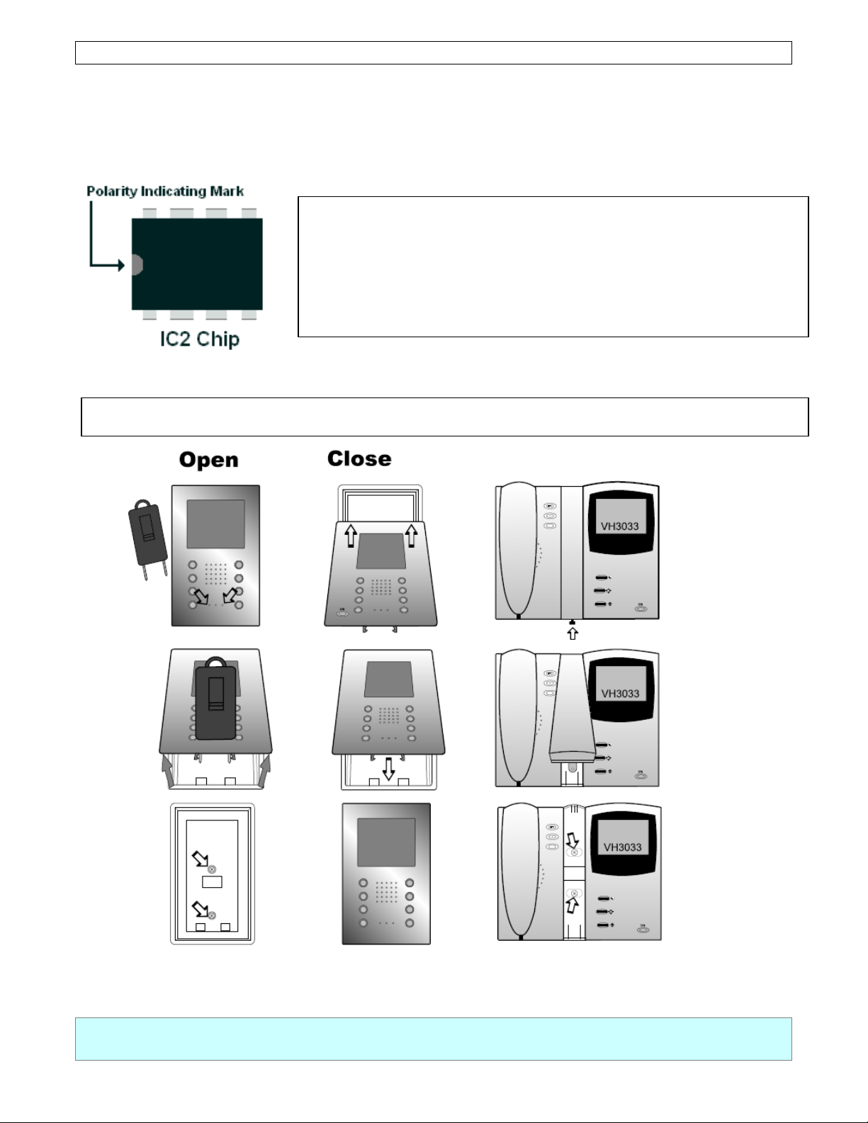
The IC2 Database Chip
The QwikBus™ system has 8 pin nonvolatile IC chips located on the back of each TSMB3
Speaker Microphone Module (in the Modular style Entry Panels) or TT33-3 Speaker
Microphone Module (in the Custom style Entry Panels). Each unit has this chip which
maintains the programming for that specific entry.
If you have to replace a TSMB3 or TT33-3 unit, you can remove
the IC2 from the old unit and install it into the new unit so you do
not have to reprogram that entrance. When doing this
replacement, be sure to install it in the correct polarity indicated
by the mark on the chip.
Opening and Closing the VFS1000/ VFS1500/VHC3033-2 Inside Stations
Arrows indicate mounting screws
NOTE: Special Tool shown above is required for opening VFS/FS panels as well as servicing
Modular Entry Panels. Part # 13510
14
Page 17

PROGRAMMING SECTION for OPEN VOICE STYLE
A
A
A
A
(
(
g
NOTE: Depending on your choice of Entry Panel, you will either be using a TT33-3 or TSMB3
Module. The TT33-3 and the TSMB3 will both be referred to in this section as the
Speaker/Microphone
Programming the QwikBus™ System -- Open Voice (VFS1500/1000 FS1500/1000)
Programming the system is easily done with two installers. One to move from apartment to
apartment working with the monitors, and one to be at the entry panel pressing the
corresponding buttons.
1. Move Dipswitch 1 at Speaker/Microphone to ON position (Enter Programming Mode).
2. Press ON/OFF Button of
the Entry Panel, Installers will be able to talk to each other).
3. Press the Entry Button to be assigned to the
Speaker/Microphone will indicate successful programming).
4. Press ON/OFF Button ofApartment Station.
5. Repeat Steps 2 through 4 forall apartments.
6. When Programming is completed move Dipswitch 1 at Speaker/Microphone to OFF
position (Normal Operating Mode).
Programming Indoor Stations for Parallel Operation
You can program up to 4 stations to ring with each pushbutton ( either for a residential
system or multiple stations in an apartment).
1. Move Dipswitch 1 at Speaker/Microphone to ON position (Enter Programming Mode).
Check that Dipswitch 2 is in the OFF position.
partment Station to be programmed. (Opens communication to
partment Station (4 beeps at the
2. Press ON/OFF Button of
communication to the Entry Panel, Installers will be able to talk to each other).
3. Press the Entry Button to be assigned to the
the Speaker/Microphone). Press ON/OFF Button of Apartment Station (turn off).
4. Move Dipswitch 2 at Speaker/Microphone to ON position.
5. Press ON/OFF Button ofApartment Station to be programmed.
communication to the Entry Panel, Installers will be able to talk to each other).
TSMB3)Hold down the “Light Button” while pressingthe EntryButton used in Step 3.
6.
OR (TT33-3) Press the same Entry Button used in Step 3.
7. Press ON/OFF Button ofApartment Station.
8. Repeat Steps 5 throu
9. Move Dipswitches 1 & 2 to OFF position.
partment Station to be programmed. (Opens
partment Station (4 beeps will sound at
Opens
h7 foreach additional parallel station.
15
Page 18
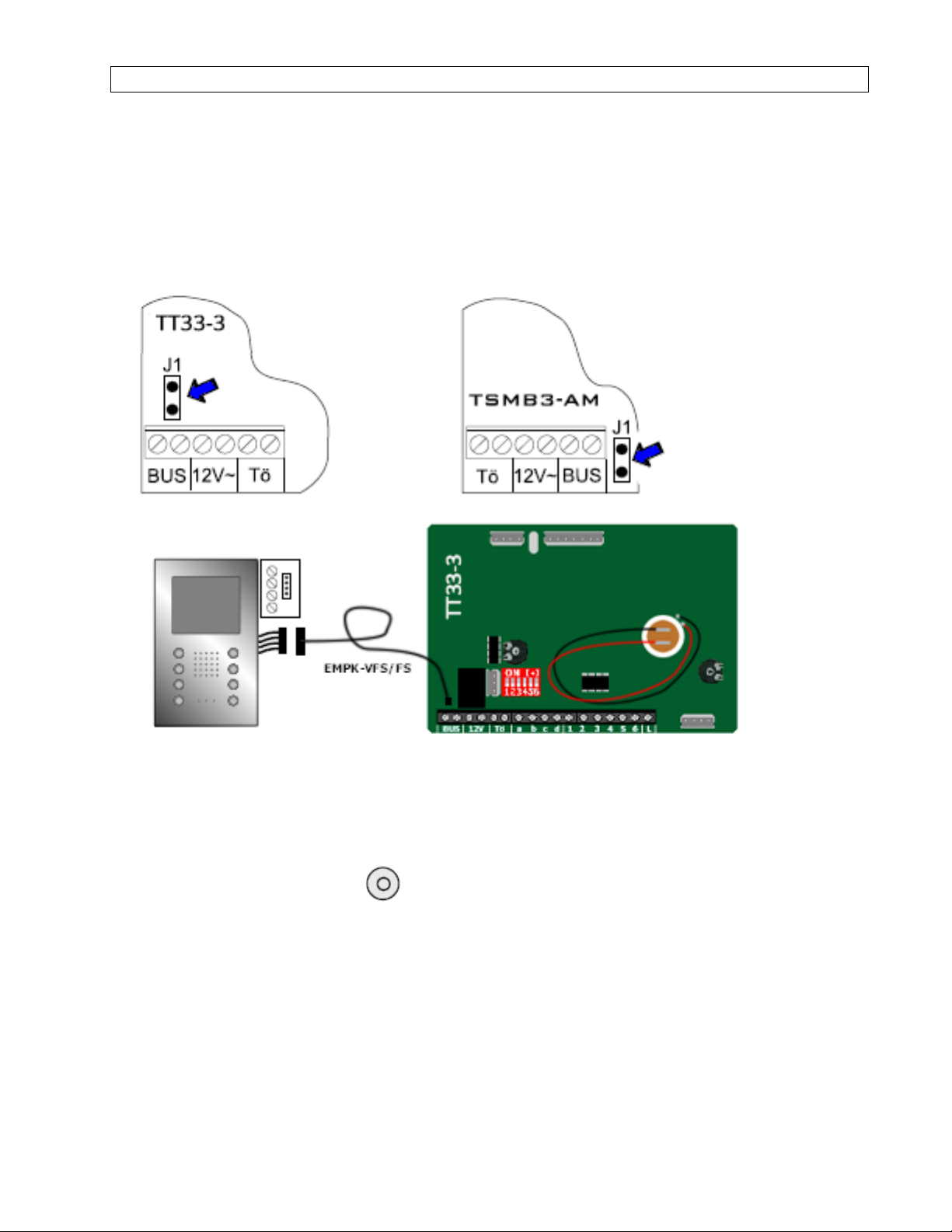
One Man Bench Programming -- Open Voice (VFS1500/1000 FS1500/1000)
If you prefer, the system can be preprogrammed on the bench to minimize your on-site
time and eliminate the necessity of a second installer. To do this the inside stations can
be connected separately one after another to the Speaker/ Microphone Module (either the
TSMB3 or the TT33-3) using the special programming cable (Part # EMPK-VFS/FS for
handset-free type stations or Part # EMPK-VH/HT for handset type stations), or just using
2 wires between the BUS terminals of both. Below is a step by step procedure for this
method.
1. Connect the TT33-3 orTSMB3 Speaker/Mic unit to BUS powerand plugin
programming cable to the J1 terminals indicated by the blue arrow.
2. Move Dipswitch 1 to ON (programming mode).
3. Plug in other end of the cable to one indoorstation as shown.
4. Hold down the light button until you hear a single tone (approx. 3 sec.)
5. Push the corresponding entry pushbutton. If the programming is successful you will
hear 4 tones at the Speaker/Mic unit.
6. Unplug the indoor station and mark it with the corresponding pushbutton to avoid a
mix-up.
7. Plug in the next indoorstation and repeat steps 4 through 6 forthe remaining units.
8. When programming is completed, Move Dipswitch #1 back to OFF (Normal mode)
16
Page 19
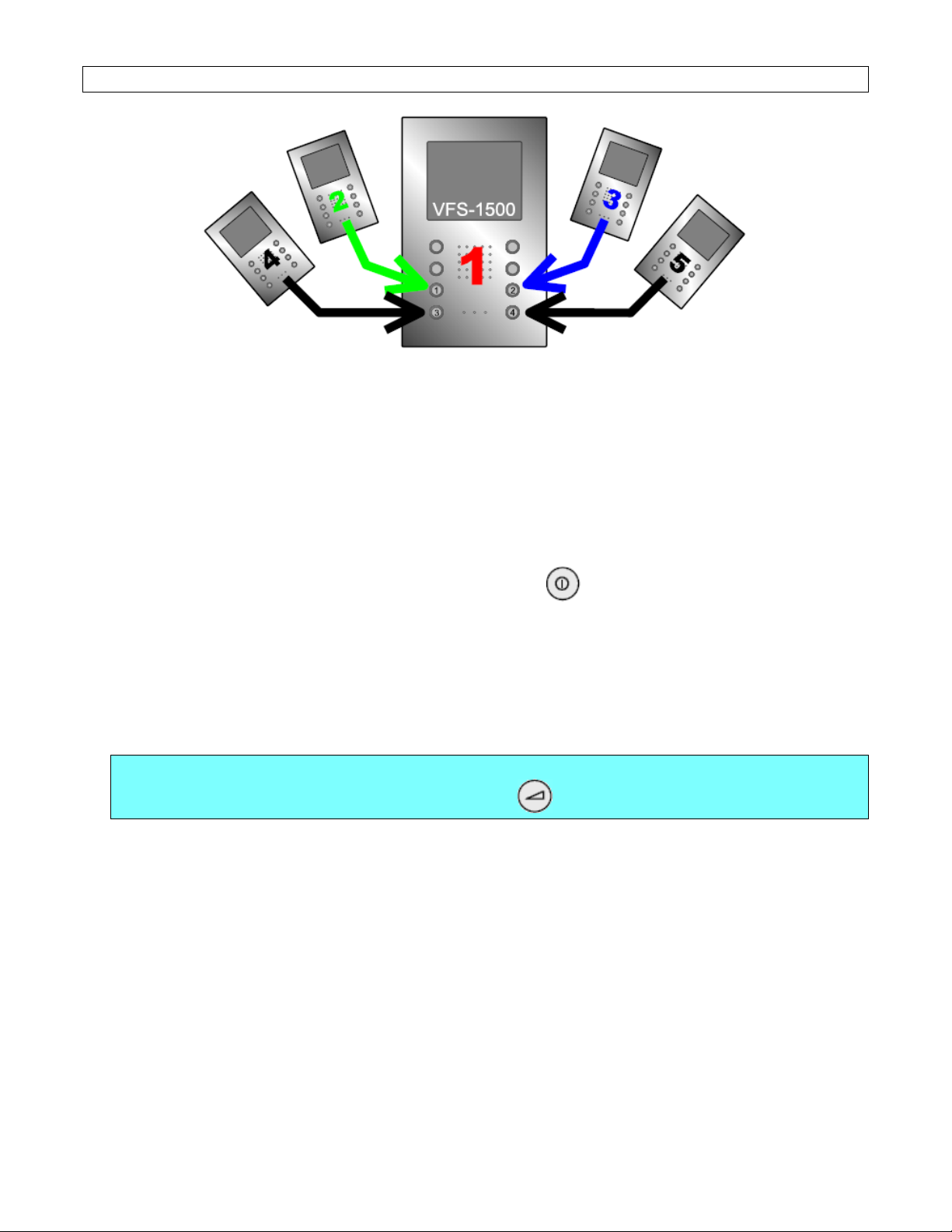
Programming Open Voice VFS1500 for Intercommunication
A
You can install up to five VFS1500 stations and program them for intercommunication in the
same residence/ apartment.
To program a VFS1500 to ring when one of the numeric buttons on another unit is pressed:
1.
t the Callingstation, press and hold the buttonyou wish to call the second station
until you hear a short tone. At this time the red LED will be blinking indicating that the
first station is in programming mode.
2. Go to the second station and press the ON/OFF button. You will hear a tone and
the system will exit programming mode. The calling station will now ring thesecond
station when that numeric button is pressed.
3. Repeat this procedure forall units beingcalled from the first station, then move to the
second station and program all it’s buttons as needed, then the third etc., until all units
are programmed.
NOTE: To leave programming mode without changing programming,
press the function button.
To delete programming from a numeric button:
1. Press and hold the button you wish to deprogram. In approx. 3 seconds you will hear a
short tone. At this time the red LED will be blinking indicating that the first station is in
programming mode.
2. Continue to depress the button until you hear the tone a second time.
The programming for that button is now deleted.
17
Page 20
PROGRAMMING SECTION for HANDSET STYLE
NOTE: Depending on your choice of Entry Panel, you will either be using a TT33-3 or
TSMB3 Module. The TT33-3 and the TSMB3 will both be referred to in this section as the
Speaker/Microphone
Programming the QwikBus™ System – Handset Style (VHC3033-2 / HT3033)
Programming the system is easily done with two installers. One to move from apartment to
apartment working with the monitors, and one to be at the entry panel pressing the
corresponding buttons.
1. Move Dipswitch 1 at Speaker/Microphone to ON position (Enter Programming Mode).
2. Lift Handset of Apartment Station to be programmed. (Opens communication to the Entry
Panel, Installers will be able to talk to each other).
3. Press the Entry Button to be assigned to the Apartment Station (4 beeps at the
Speaker/Microphone will indicate successful programming).
4. Hang up Handset of Apartment Station.
5. Repeat Steps 8 through 10 for all apartments.
6. When Programming is completed move Dipswitch 1 at Speaker/Microphone to OFF
position (Normal Operating Mode).
Programming Indoor Stations for Parallel Operation
You can program up to 4 stations to ring with each pushbutton (either for a residential
system or multiple stations in an apartment). Up to 8 stations can be programmed to ring
with the special TSMB3-8 module.
1. Move Dipswitch 1 at Speaker/Microphone to ON position (Enter Programming Mode).
Check that Dipswitch 2 is in the OFF position.
2. Lift Handset of Apartment Station to be programmed. (Opens communication to the
Entry Panel, Installers will be able to talk to each other).
3. Press the Entry Button to be assigned to the Apartment Station (4 beeps will sound at
the Speaker/Microphone). Hang up Handset of Apartment Station.
4. Move Dipswitch 2 at Speaker/Microphone to ON position.
5. Lift Handset of next Apartment Station to be programmed. (Opens communication to
the Entry Panel, Installers will be able to talk to each other).
6. (TSMB3) Hold down the “Light Button” while pressing the Entry Button used in Step 3.
OR (TT33) Press the same Entry Button used in Step 3.
7. Hang up Handset of Apartment Station.
8. Repeat Steps 10 through 17 for each additional parallel station.
9. Move Dipswitches 1 & 2 to OFF position.
18
Page 21
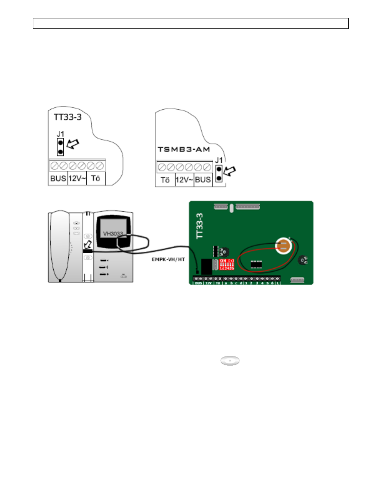
One Man Bench Programming -- Handset Style (VHC3033-2 / HT3033)
r
g
g
r
If you prefer, the system can be preprogrammed on the bench to minimize your on-site
time and eliminate the necessity of a second installer. To do this the inside stations can
be connected separately one after another to the Speaker/ Microphone Module (either the
TSMB3 or the TT33-3) using the special programming cable (Part # EMPK-VFS/FS for
handset-free type stations or Part # EMPK-VH/HT for handset type stations) or by running
2 wires between the BUS terminals of both. Below is a step by step procedure for this
method.
1. Connect the TT33-3 orTSMB3 Speaker/Mic unit to BUS powerand plugin
programming cable to the J1 terminals indicated by the blue arrow.
2. Move Dipswitch 1 to ON (programming mode).
3. Plug in other end of the cable to one indoo
4. On the inside station, hold down the light button
(approx. 3 sec.)
5. Push the correspondin
hear 4 tones at the Speaker/Mic unit.
6. Unplu
mix-up.
7. Plug in the next indoo
8. When programming is completed, Move Dipswitch #1 back to OFF (Normal mode)
the indoor station and mark it with the correspondingpushbutton to avoid a
entrypushbutton. If the programmingis successfulyou will
station and repeat steps 4 through 6 forthe remaining units.
station as shown.
until you hear a single tone
19
Page 22
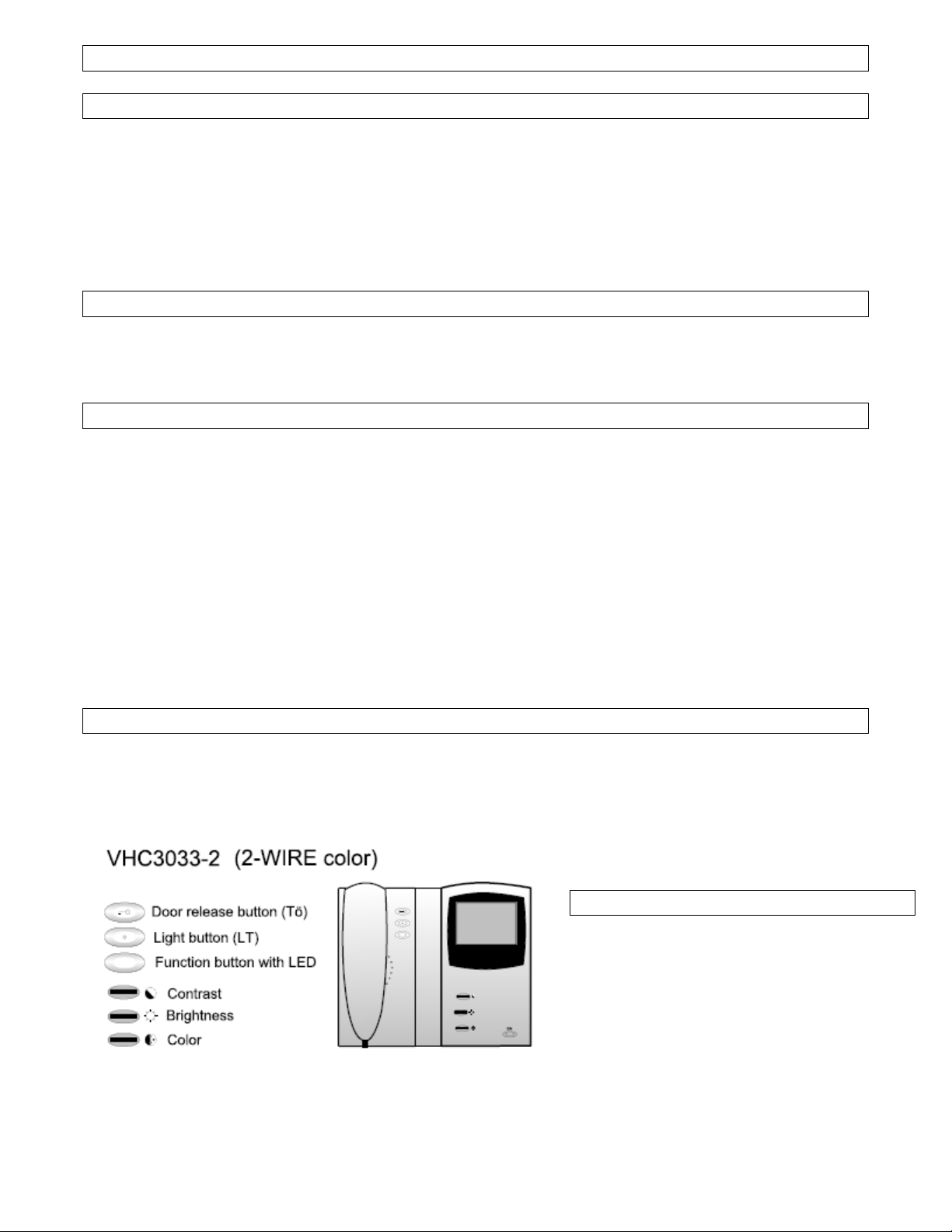
USER Operation of the VHC3033-2 Color Handset
General Operation
After a visitor has rung the bell at the entrance, the monitor will turn on automatically. You
can lift the handle and talk with the visitor. You are also able to activate the door opener.
When hanging up the handset, the communication will end and the monitor willturnoff
automatically. Up can switch on the monitor at any time by pressing the ON button located at
the bottom right of the monitor. To switch off the monitor hold the ON button for approx. 3
seconds.
Manually switching Multiple Cameras ( if equipped)
Turn on the monitor by pressing the ON button. Pushing this button again will cycle through
all available cameras on the system.
Changing the Ring sound of your inside station
You can select one of eight different doorbell signals for each indoor station by the following
method:
1. Lift the handset and wait until the red LED and busy tone stop. (make sure the handset
hasn’t been called shortly before, otherwise lift handset and hang up again to stop
communication).
2. Now you can listen to all the different ringtones one after the other by keeping the
function button depressed until the next tone starts. The last ringtone heard will be
stored automatically. When finished hang up the handset.
3. The ringtone sent by the optional doorbell button (connected at E & T) cannot be
changed.
4. In systems with more than one entrance there is a differentiation between the ringtone
automatically.
Adjusting the Volume of the Ringtone
1. Keep the Function Button depressed with the handset hung up and volume will
decrease slowly to mute and then increase to full volume.
2. Release the button at the desired volume level. (make sure the handset hasn’t been
called shortly before, otherwise lift handset and hang up again to stop communication).
20
Replacing an Indoor Station
The new station must be programmed
into the system (See programming
Instructions Page 16)
Page 23
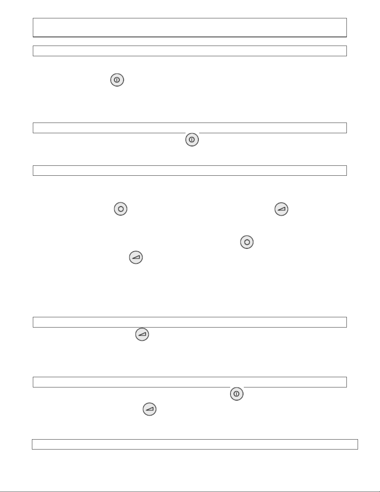
USER Operation of the VFS1000 / VFS1500 Open Voice COLOR Monitor
& FS1000/FS1500 Audio only stations
General Operation
After a visitor has rung the bell at the entrance, the monitor will turn on automatically. You
can push the ON/OFF button and talk with the visitor. You are also able to activate the
door opener. Pushing the ON/OFF button will end the communication and the monitor will
turn off automatically. You can switch on the monitor at any time by pressing the ON/OFF
button. To switch off the monitor hold the ON/OFF button for approx. 3 seconds.
Manually switching Multiple Cameras ( if equipped)
Turn on the monitor by pressing the ON/OFF button. Pushing this button again will cycle
through all available cameras on the system.
Changing the Ring sound of your inside station
You can select one of eight different doorbell signals for each indoor station by the following
method:
5. Keep the LIGHT button depressed and push the FUNCTION button. This will
play the first ringtone (make sure the station hasn’t been called shortly before,
otherwise press the ON/OFF button twice to stop communication).
6. To hearthe next ringtone, continue keeping the LIGHT button depressed and
push the FUNCTION button again. The last ringtone heard will be stored
automatically.
7. The ringtone sent bythe optional doorbell button(connected at E & T)cannot be
changed.
8. In systems with more than one entrance there is a differentiation between the ringtone
automatically.
Adjusting the Volume of the Ringtone
1. Keep the Function button depressed and volume will decrease slowly to mute
and then increase to full volume.
2. Release the button at the desired volume level. (make sure the station hasn’t
been called shortly before, otherwise press the ON/OFF button twice to stop
communication).
Adjusting the Brightness of the Monitor
1. Turn on the monitorby pressing the ON/OFF button.
2. Keep the Function button depressed and brightness will decrease slowly
and then increase to full brightness. Release the button at the desired
brightness level. Turn off monitor.
Replacing an Indoor Station
The new station must be programmed into the system (See programming Instructions Page 13)
21
 Loading...