

Page 1
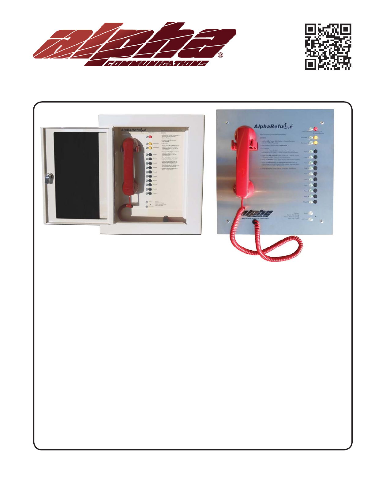
AlphaRefuge™ 2100 Series (V2) Area of Refuge and Rescue
Assistance system Installation, Use and Wiring Instructions
Pre-Installation Requirements:
• Either 24VDC or 110/120VAC Power
• Analog Telephone Line (POTS, PBX, Or Central Offi ce) with RJ11 connectors. If you are installing
on a Voice Over IP (VoIP) phone system, you must obtain from Alpha Communications® or the
phone system provider, an Analog Telephone Adaptor (ATA) programmed to provide a disconnect (CPC) signal.
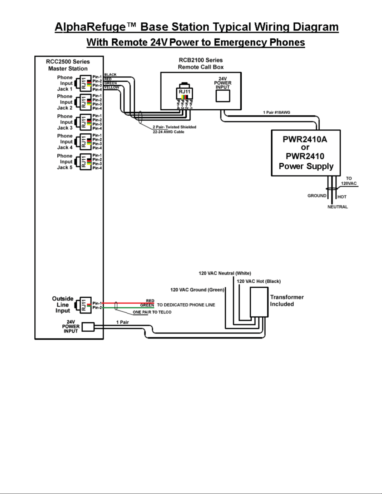
• Twisted, shielded, 22 to 24 gauge, 4 wire cabling (CAT 5 rating or greater is preferred) to connect
between each Emergency Phone and the AlphaRefuge™ Command Center Station. RJ11
connectors should be attached for connection to the Base Station. Make sure to maintain wire
color polarity from the phone connection to the RJ11 jack at the Base Station. See the Wiring
Diagrams on Pages 4 through 7.
NOTE: Terminals and markings shown in this manual may not be in the order in which they appear
on the actual equipment. When installing, observe all national and local electrical and building
codes.
Copyright© 2011-2013, Alpha Communications®, All Rights Reserved.
AWD186 Rev. 2 (08/2014)
Page 2
Installation:
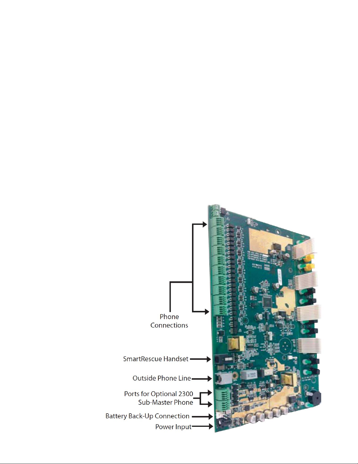
• Remove the front cover from the Base Station and punch out conduit knockouts for analog phone
line and Phone cabling runs.
• Mount Base Station to the wall using suitable mounting screws (not included).
• Connect the red backup battery cable to the battery terminal.
• Connect an analog phone line to the RJ11 receptacle located on the lower left of the circuit board
(See Diagram A below).
• Take 4 wire cabling and insert into push connectors along left side of circuit board following wiring on
pages 4 through 7. Terminate connector onto other end of wires to connect to the Emergency Phone.
• Shields from the cabling runs (if used) should be attached to one of the mounting screws on the
housing.
• Mount the front cover on the Base Station.
• Direct wire to a 120VAC power source (see instructions on Page 3) or 24VDC Power Supply.
DIAGRAM A
2
Page 3
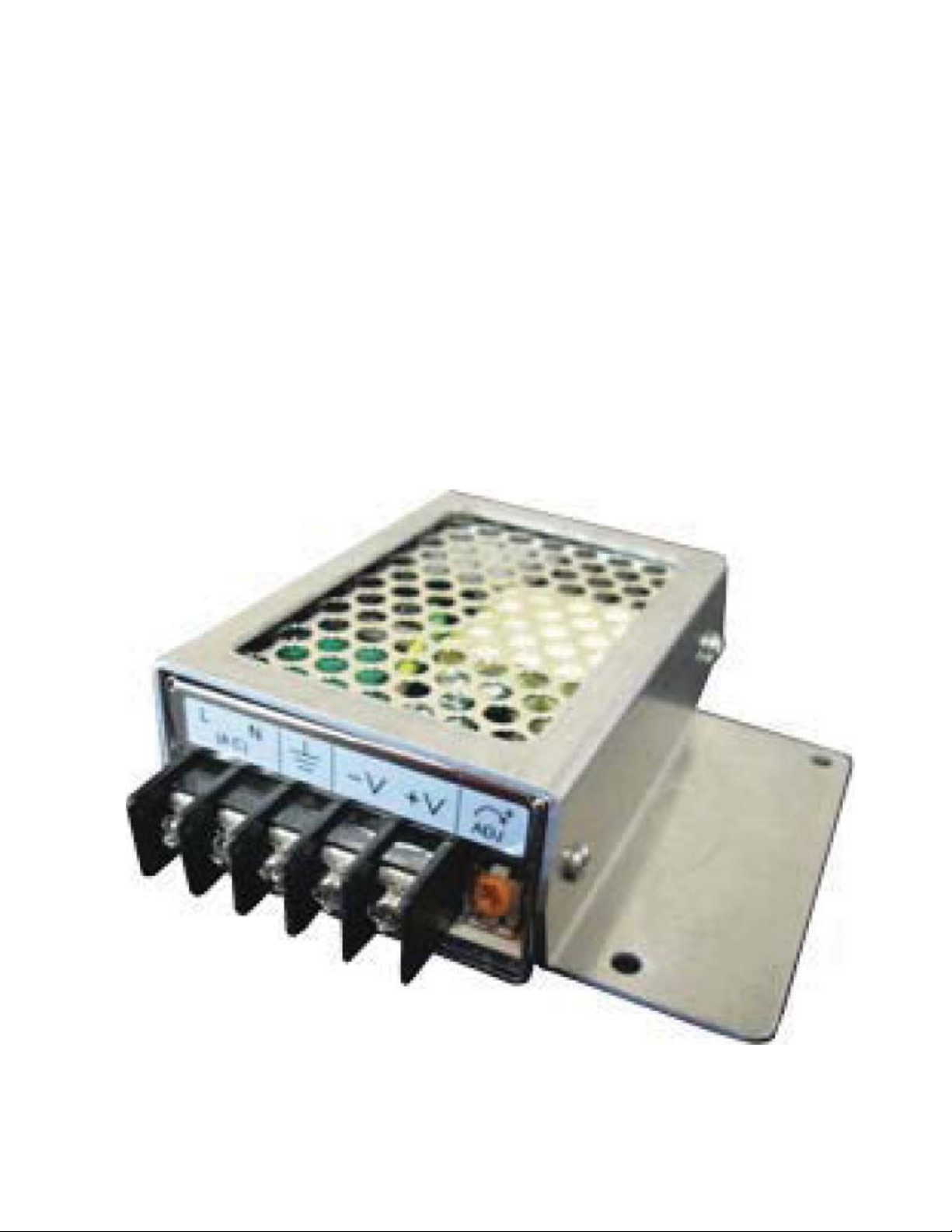
Installation:
• Connect the hot wire of the 120VAC to the L screw on the power supply
• Connect the neutral wire of the 120VAC to the N screw on the power supply
• Connect the ground wire of the 120VAC to the Ground screw on the power supply
• Connect one lead of the DC power connection to the –V screw and the other to the +V screw (polarity is not important)
• Connect the DC power connection to the AlphaRefuge™ Control Board. The power connection is
on the lower left hand side of the board
3
Page 4
45678
Page 5
Page 6
Page 7

Page 8

Programming Options for Base(s):
*Note: You must still program each Emergency Phone after programming Base Station
A. Program Base Station to allow Emergency Phones to call it then a Secondary Outside Number
1. Unplug Power Supply and Battery Back-Up from Base Station
2. Hold down Phone 1, Phone 3, and Phone 5 Buttons.
3. Re-connect power to Base Station
4. Release buttons- will hear a confi rmation tone
5. Press Phone 2 button, Red Button, and Phone 1 button
6. Press Submaster 2 Button then Submaster 1 Button
B. Program Base Station to allow Emergency Phones to call an Outside Number Only (Factory Default)
1. Unplug Power Supply and Battery Back-Up from Base Station
2. Hold down Phone 1, Phone 3, and Phone 5 buttons.
3. Re-connect power to Base Station
4. Release buttons- will hear a confi rmation tone
5. Press Phone 2 Button, then Red Button, then Submaster 2 Button and then the Phone 5 Button
6. Press Submaster 2 Button then Submaster 1 Button
NOTE: You MUST program each remote call box after
programming base station.
Programming Options for Phone(s):
A. Program Emergency Phone(s) in Consolidator mode - (Optional)
1. Press Enter to get into program mode
2. Press 7, Enter
3. For Phone(s) 1-5; Press *, 1-5
• Example: For Phone 1, Press 7, Enter, *, 1
• Example: For Phone 2, Press 7, Enter, *, 2
4. For Phone(s) 6-10; Press #, 1-5
• Example: For Phone 6, Press 7, Enter, #, 6
• Example: For Phone 7, Press 7, Enter, #, 7
5. Press and hold Stop for 2-3 seconds until warble sound to exit programming
6. Confi rm operation by calling the phone number Phone(s) are installed on; all phones will answer. To speak
with individual phone(s): (for phone(s) 1-5 press *1, *2, *3, *4 or *5) or (for phone(s) 6-10 press #1, #2, #3, #4
or #5) to speak with all phones press *0
B. To program Phone(s) to call the Base unit fi rst and then if no answer to dial secondary emergency numbers
1. Press Enter to get into program mode
2. Press 1, Enter, (Phone Number 1), Stop
3. Press 2, Enter, (Same number programmed in step 2), Stop
4. If you wish to dial additional emergency numbers, press 3-5, Enter, (Phone Number), Stop (for each
additional emergency phone number)
5. Press and hold Stop for 2-3 seconds until warble sound to exit programming
C. To program Phone(s) to dial standard emergency numbers
1. Press Enter to get into program mode
2. Press 1, Enter, (Phone Number), Stop
3. If you wish to dial additional emergency numbers, press 2-5, Enter, (Phone Number), Stop (for each
additional emergency phone numbers)
4. Press and hold Stop for 2-3 seconds until warble sound to exit programming
D. To program Location Message
1. Press Enter to get into program mode
2. To turn on message press 1, 3, Enter, 2 or for no message press 1, 3, Enter, 0
3. Press 6, Record, (Wait for Beep, Speak your message), Stop (To replay message press 6, Play )
4. To program frequency of message press 1, 3, Enter, _
• Pressing 1 plays message once;
• Pressing 2 plays message twice (this is the standard confi guration);
• Pressing 3 plays message until called party presses * on their phone
5. Press and hold Stop for 2-3 seconds until warble sound to exit programming
Page 9

Operation:
A. Once all connections are made the following LED’s should be lit:
1. Power LED, located on bottom edge of the faceplate, will be constant lit green
2. Battery LED, also located on bottom edge of the faceplate, will be constant lit.
• Red = Low level charge
• Yellow = Mid level charge
• Green = Full Charge
B. Initiate a Call to an Emergency Phone or Sub-Master from the Base Station
1. Lift handset on Base Station
2. Press the Talk button corresponding to the Emergency Phone or Sub-Master you wish
3. The green LED will light next to that button
4. You should have two way communication to that Phone
5. You can place the Phone on hold by pressing the Talk button a second time.
6. To resume communication press the Talk button a third time.
7. To disconnect hang up handset.
C. Emergency Phone places a call into the Base Station
1. You will hear an alternating audible tone at the Base Station indicating a call has been initiated by
one of the Phones.
2. The corresponding green LED, will light on the Base Station next to the phone that placed the call.
3. Lift handset and there is two-Way Communication between the and the Emergency phone. The
handset can be hung up on the Base Station at any time to end the call.
D. Emergency Phone places a call into the Base Station then an outside number
1. You will hear an alternating audible tone at the Base Station indicating a call has been initiated by
one of the Phones (if programmed to call outside line only, no tone)
2. The corresponding green LED will light on the Base Station next to the phone that placed the call.
3. If call is not answered at the Base Station the Emergency Phone will hang-up and re-dial the
second number programed into the Emergency Phone.
4. The CO Line LED, located next to Red Button, will also be lit indicating that the outside line is
active. Two-way communication can then take place between the outside line and emergency
phone once the call is answered.
5. The Base Station can join the conversation by the handset being lifted at the Base Station.
6. To talk to Rescue Services only from the Base Station, place the Phone on hold by pressing the
corresponding Talk button. To bring them back into the conversation, press the Talk button again.
7. To disconnect Rescue Services, press the red button at the top of the face plate. The Rescue
Services LED will go off and leave you communicating with the Phones only.
9
Page 10

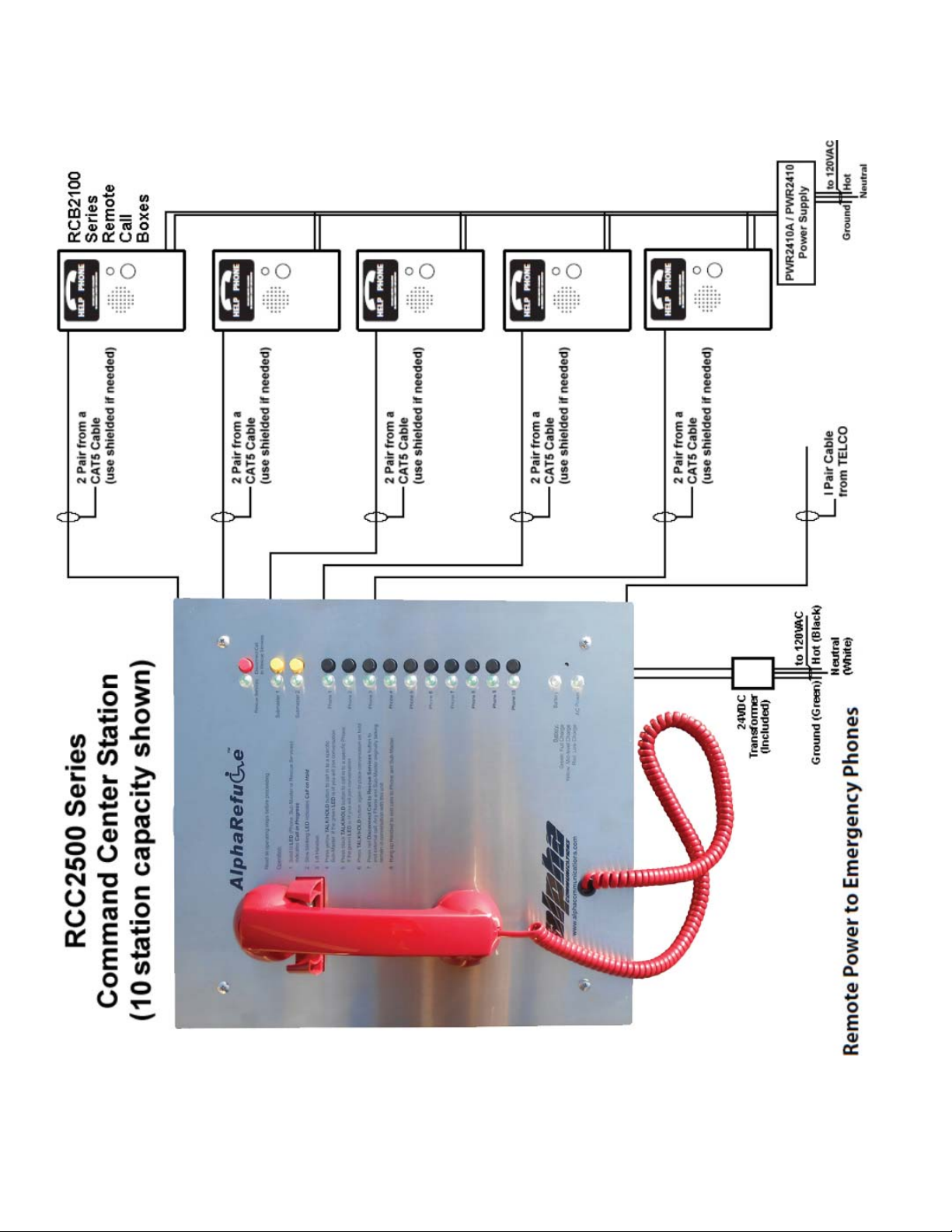
Sub-Master Installation and Operation:
A. Installation
1. Mount the Sub-Master to the wall in desired location.
2. Run twisted, 24 or 22 gauge, 4 wire cabling (CAT-5 rating or greater is preferred) to connect SubMaster to Base Station
B. Operation
1. Lift handset
2. To dial individual phones connected to Base Station:
• Press *1 (Phone #1)
• Press *2 (Phone #2)
• Press *3 (Phone #3)
• Press *4 (Phone #4)
• Press *5 (Phone #5)
• Press #1 (Phone #6)
• Press #2 (Phone #7)
• Press #3 (Phone #8)
• Press #4 (Phone #9)
• Press #5 (Phone #10)
B. Typical Wiring Diagram
10
Page 11

1112131415
Page 12

Page 13

Page 14

Page 15

RCB2100SF Flush Mount St. Steel
Remote Call Box Station
Page 16

Remote Call Box Station
RCB2100SF Flush Mount St. Steel
16
Page 17

NOTE: Terminals and markings shown in this manual may not be in the order in which they
appear on the actual equipment. When installing, observe all national and local electrical and
building codes.
ALPHA COMMUNICATIONS® • 42 Central Drive • Farmingdale NY 11735-1202
TOLL-FREE TECHNICAL LINE 1-800-666-4800 • Phone: 631-777-5500 • Fax: 631-777-5599
WEBSITE: www.AlphaCommunications.com • EMAIL: info@alphacommunications.com
17
 Loading...