

Page 1
IL882
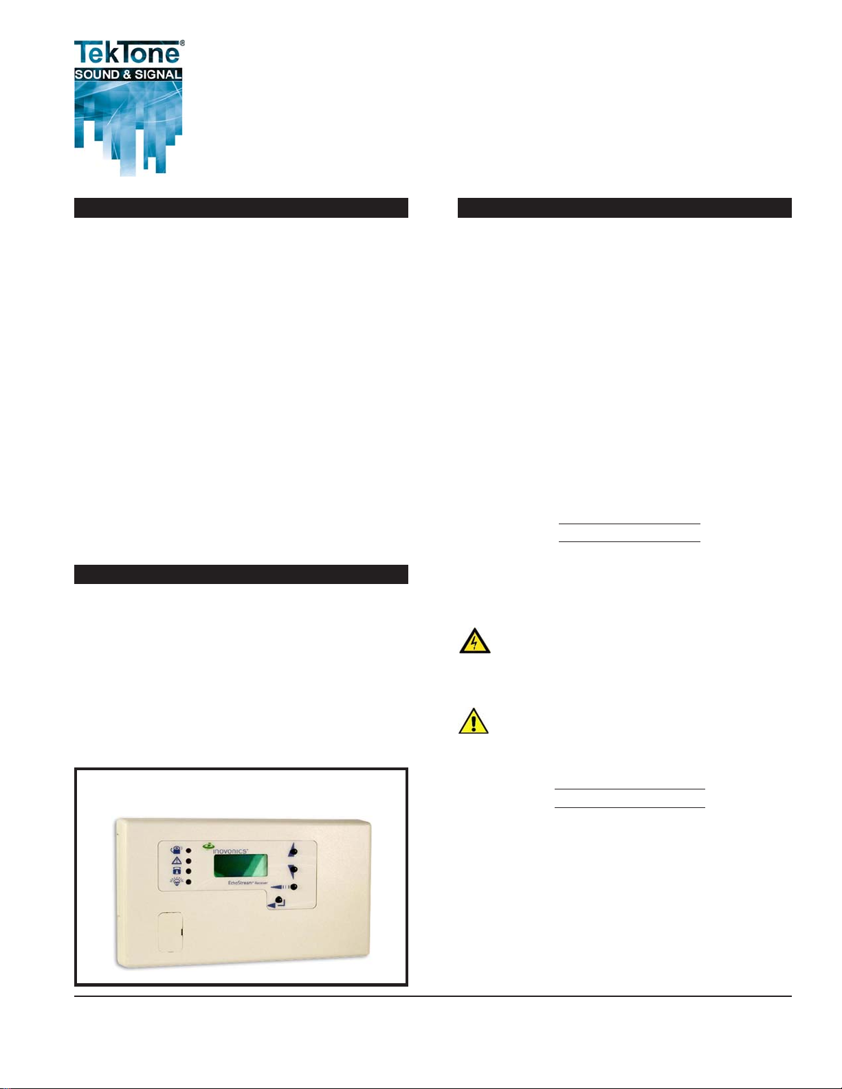
NC505ES Remote LCD Receiver
Installation & Operating Instructions
Contents
Chapter 1—Introduction..................................................... 1
About This Manual .........................................................1
Theory of Operation ........................................................1
What’s in the Box ............................................................3
Features ...........................................................................3
Chapter 2—Installation ...................................................... 3
Mounting ........................................................................3
Connections ....................................................................3
Chapter 3—Programming & Operation ............................ 4
Receiver Menus...............................................................4
Program Relay Outputs ...................................................4
Change Password ............................................................5
Monitor Signal Strength ..................................................5
Set up Transmitter Points 1–16........................................5
Point Status ..................................................................... 6
Event Log ........................................................................6
Alarms and Faults............................................................6
Appendix—Device Specifications ..................................... 6
Illustrations
Figure 1—NC505ES Remote LCD Receiver .....................1
Figure 2—Inside the NC505ES ........................................2
Figure 3—Wiring Examples .............................................2
Figure 4—NC505ES Indicators & Function Buttons .......4
Figure 5—NC505ES Programming Menu Tree.................5
Section E
Rev. 2 - 06 /2011
Chapter 1—Introduction
The NC505ES Remote LCD Receiver allows users of the
Tek-CARE®500 Wireless Emergency Call System to connect
external dome lamps and dialers to the system. This provides an
alternate annunciation path, in addition to the normal TekCARE®500 screen. The NC505ES is not dependent upon the T ekCARE®500’s master station computer . It features 6 separate, drycontact outputs that can be programmed for activation of up to 16
unit addresses (transmitters) on the T ek-CARE®500 system.
The NC505ES is programmed using its buttons and display , and
has an access code to safeguard completed programming. The
case has built-in tamper detection outputs for connection to an
external alarm system. All dry contact outputs are individually
configurable for latching, follower or momentary activation. The
NC505ES is designed for indoor use only , and cable access and
connections are hidden. The face of the unit features a clean
appearance with visual indication of the status of all 6 outputs.
About This Manual
This manual is designed to assist with installation of this
T ekTone product. Each component of the system is described
with step-by-step instructions to facilitate hardware installation
and software configuration.
1 . Although this is a low voltage unit, take care on wire
termination at transformer and mains line outlet.
2 . Remove power when installing cabling.
3 . Use ESD wrist strap when installing cables.
1. Use proper splicing techniques.
2 . Verify proper polarity of wires.
3 . Use protective eyewear when clipping leads.
Figure 1—NC505ES Remote LCD Receiver
In a facility with a T ek-CARE®500 wireless emergency call system,
the NC505ES Remote LCD Receiver may be used to activate a
local dialer or turn on a corridor dome light in response to a call.
Note: Central Monitoring is a feature of the Tek-CARE®500 system.
The NC505ES is configured locally to an area covering up to 16
transmitters and 6 relay outputs. Multiple units are used to
provide full coverage of a floor or building. The NC505ES
accepts transmissions only from transmitters, and does not
accept signals that are rebroadcast. Therefore the NC505ES
must be near the devices that it is to receive signals from.
Theory of Operation
ALPHA COMMUNICATIONS®• 42 Central Drive • Farmingdale, NY 11735-1202
Toll-Free Technical Line: 1-800-666-4800 • Phone: (631) 777-5500 • Fax: (631) 777-5599
Website: www.AlphaCommunications.com
• Email: info@alphacommunications.com
Page 2
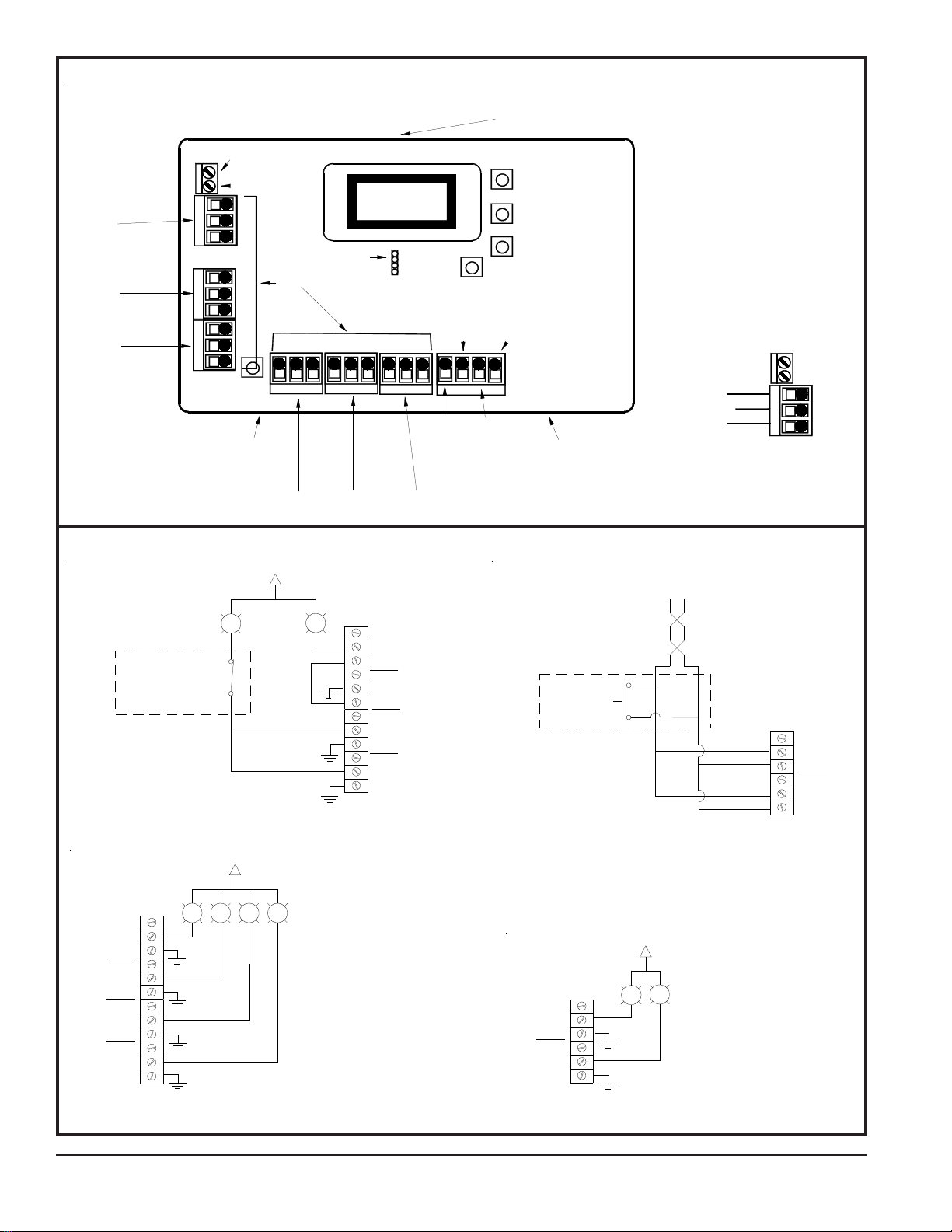
Figure 2—Inside the NC505ES
A
COM 1
COM 2
COM 3
SPECIAL PURPOSE
ALARM SYSTEM
KEY-SWITCH OR
SOME SORT OF
SECURED SWITCH
BYPASS
LOAD DRIVING
OUTPUTS CONFIGURED:
ALARM ACTIVATION
FOLLOWER MODE
ETC.
( N.C. )
Figure 3a—Normally Closed Switch
- OR -
B
C
A
H
COM 4
I
COM 5
COM 6
G
F
D
E
A
A - HOUSING RELEASE TAB
B - POWER
C - GND
D - POWER LOSS OUTPUT
E - RESET INPUT
F - TAMPER OUTPUT
G - JAM OUTPUT
H - OUTPUT TERMINALS
I - FREQUENCY SELECT
POWER
GND
IL882 NC505ES INSIDE PANEL TERM INALS REV0 072209
NC
COM
NO
Figure 3—Wiring Examples
PANIC,
5 OR 6
13
14
15
AND
16
N.C.
COM.
N.O.
N.C.
COM.
N.O.
N.C.
COM.
N.O.
N.C.
COM.
N.O.
1
4
2
3
SPECIAL PURPOSE
ALARM SYSTEM
PUSHBUTTON
( N.O. )
ETC.
PANIC
DRY CONTACT
OUTPUTS CONFIGURED:
ALARM ACTIVATION
FOLLOWER MODE
N.C.
COM.
N.O.
N.C.
COM.
N.O.
1
2
Figure 3b—Normally Open Switch
DOME LAMPS
4
BUZZERS
DOOR RELEASES
ETC.
OUTPUTS CONFIGURED:
ALARM ACTIVATION
FOLLOWER MODE
1
2
3
4
N.C.
COM.
N.O.
N.C.
COM.
N.O.
N.C.
COM.
N.O.
N.C.
COM.
N.O.
2
1
3
Figure 3c—Corridor Lights
Page 2 • IL882 NC050ES Remote LCD Receiver Manual
1
2
6
N.C.
COM.
N.O.
N.C.
COM.
N.O.
5
Figure 3d—Output to Dialer
Copyright © TekTone Sound & Signal Mfg., Inc. All Rights Reserved.
DIALER
ALARM SYSTEM
OUTPUTS CONFIGURED:
ALARM ACTIVATION
SET MODE PER DIALER
Page 3

What’s in the Box
• 2 pan head screws
• 2 plastic anchors
• 2 squares of two-sided tape
• 1 two-pin jumper
• 1 OEM installation sheet
Select the Frequency Band
The NC505ES Remote LCD Receiver can use a range of
radio frequencies, and must be configured for your
geographic area. T o configure the receiver:
1. Place a selection jumper on the appropriate frequency
band selection pins. (See Figure 2.)
Please note: The NC505ES requires a PK505 transformer,
ordered separately. Please verify that all power supplies are
available before installation.
Features
• Six onboard Type C relay outputs for N/O or N/C operation.
• Jam detection monitors all channels for interference.
• A reset terminal is provided in the receiver to allow external
receiver resets.
• A tamper terminal is provided in the receiver to allow external
tamper monitoring.
• Add up to 16 EchoStream transmitters.
• Two-line text display.
Chapter 2—Installation
Mounting
Use the provided anchors and screws to mount the receiver in
a location accessible for future maintenance. Caution: Mount
the receiver in a location removed from metal. Metal objects
(duct work, wire mesh screens, boxes) will reduce the reception
range.
• Leave the jumper off the pins to set the frequency
range to 902–928 MHz for North America. Note:
North America is also selected when the jumper is
attached to only one pin. This prevents the jumper
from being lost when selecting North America.
• Place the jumper on the top two pins, marked AUS,
to set the frequency range to 915–928 MHz for
Australia.
• Place the jumper on the bottom two pins, marked NZ,
to set the frequency range to 921–928 MHz for New
Zealand.
2 . Cycle power to reset.
Connect Output and Input Cabling
Refer to Figure 2 for connection points.
1 . Connect cabling to the power loss output. The optional
power loss output is a normally closed (N/C) output that
reports power loss to an external device.
2. Connect cabling to the tamper output. The optional
tamper output is a normally open (N/O) output that
reports receiver case tamper to an external device.
Connections
Connect Power Cabling
Before beginning startup, connect power to the receiver:
1. Use a small screwdriver to press the three housing
release tabs on the top or bottom of the receiver and
separate the housing.
2. Connect power cabling to the Power (Vs) and GND
connections. (See Figure 2.)
3. Power source must be 11–14 VDC. Power supply must be
unswitched, uninterrupted, and regulated. Use TekTone
part number PK505.
3. Connect cabling to the jam output. The optional jam
output is a normally closed (N/C) output that opens when
noise thresholds on all transmission channels remain
above a predetermined value for more than 20 seconds.
4. Connect cabling to the reset input. The optional reset
input circuit permits installation of a remote momentary
normally open (N/O) switch to clear faults, unlatch relay
outputs and reset the receiver to a normal state.
5 . Connect cabling to the output terminals. The NC505ES
provides six Form C relay outputs.
®
6 . Close the NC505ES receiver housing.
Field Wiring Examples
Figure 3 shows various uses of the relay outputs from the
NC505ES. Wire size should be no smaller than 22 gauge
and no larger than 18 gauge (due to housing space). Use 18
gauge cable to connect dome lights and the external power
supply.
Copyright © T ekT one Sound & Signal Mfg., Inc. All Rights Reserved.
IL882 NC050ES Remote LCD Receiver Manual • Page 3
Page 4

Chapter 3—Programming & Operation
Receiver Menus
There are three main menus (see Figure 5):
• Install & Service
• Event Log
• Point Stataus
Select the Install & Service menu to program relay outputs,
change the password, view the signal strength, delete points,
register transmitters or set up points for any of the programmed
transmitters. Note: A password is required to access the Install
& Service menu. The default password is 3446.
Program Relay Outputs
1 . From the Install & Service menu, press the ENTER button at
the PROGRAM OUTPUT prompt.
2 . PROGRAM OUT 01 is displayed.
3 . Using the UP and DOWN buttons to scroll, select OUTPUT 01
for programming, and press the ENTER button.
4. OUT 01 FOLLOWER is displayed. Use the UP and DOWN
buttons to select one of the following four options, and then
press the ENTER button to select the appropriate output type:
Follower—The relay output reflects the transmitter’s alarm
status. Press the ENTER button to select this option.
Toggle—The relay output changes state each time the device
sends a new activation. A minimum of five seconds must
elapse before the relay output can send a new activation.
• Press the
ENTER button to select this option. The
display shows INACTIVE. Inactive time prevents
output chatter. The default is 4.0 seconds. The valid
range is 2.0 to 99.5 seconds, in half-second increments.
• Use the UP and DOWN buttons to scroll through the
digits; press the
ENTER button to select and advance
to the next digit.
• When finished, press the ENTER button again to
complete the setting.
Momentary—The relay output turns on for a programmed
number of seconds, then turns off, regardless of the
device status.
• MOMENT displays when selected. This sets the
number of seconds that the output will remain activated. The default is 4.0 seconds. The valid range is
0.5 to 99.5 seconds, in half-second increments.
• Use the UP and DOWN buttons to scroll through the
digits; press the ENTER button to select and advance
to the next digit.
• When finished, press the ENTER button again to
complete the setting.
5 . The display shows PGM DONE. Press the ENTER button to
program another relay output, or press the BACK button to
return to the Install & Service menu.
Latching—The relay output turns on when activated and
remains on until the receiver is reset. Press the ENTER
button to select this option.
Figure 4—NC505ES Indicators & Function Buttons
A
B
C
D
F
K
Inovonics
E
READY
6 . Repeat steps 1–5 for relay outputs 02–06.
G
H
I
J
A - OUTPUT LED
B - FAULT LED
C - NOT USED
D - POWER LED
E - LCD DISPLAY
F - DECODE LED
G - UP BUTTON
H - DOWN BUTTON
I - BACK BUTTON
J - ENTER BUTTON
K - RESET BUTTON
IL882 NC505ES FRONT PANEL DISPLAY REV1 120909
Page 4 • IL882 NC050ES Remote LCD Receiver Manual
Copyright © T ekT one Sound & Signal Mfg., Inc. All Rights Reserved.
Page 5

Change Password
Passwords can be up to eight digits long. The default password
is 3446. T o change the password:
Set up Transmitter Points 1–16
Caution: When programming points, be careful not to map
faults to the same output as alarms.
1 . From the Install & Service menu, press the ENTER button at
the CHANGE PASSWORD prompt.
2. Use the
UP and DOWN buttons to scroll through the digits;
press the ENTER button to select and advance to the next
digit. To select a space, press the
ENTER button without
selecting a digit.
3. When finished, press the ENTER button again to complete
the setting.
4 . When PASSWORD CHANGED displays, press the
DOWN button to return to the menu.
UP or
Monitor Signal Strength
The Signal Strength option is used to measure signal strength
and troubleshoot installation problems.
1. At the SIGNAL STRENGTH prompt, press the
ENTER button.
POINT 01 is displayed, along with a signal quality of GOOD,
WEAK or NO SIG.
2 . Use the UP and DOWN buttons to scroll through the registered
transmitters.
3 . Press the ENTER button again to view level (LV) and margin
(MA). LV indicates the overall signal strength; MA indicates the signal strength minus the background noise.
4 . To reset signal data, use the UP and DOWN buttons to leave
and return to the transmitter you are monitoring.
5. Press the BACK button to return to the menu.
1 . From the Install & Service menu, press the ENTER button at
the SETUP POINT prompt.
2. Use the
UP and DOWN buttons to scroll through the points;
press the ENTER button to select the point to be set up. TX
REGISTRD displays if a transmitter is currently registered to
this point; TX NOT REGSTRD displays if no transmitter is
registered to this point.
3. Press the
ENTER button to set up the point. The following
eight setup options are available:
Supervision Time—Sets time limit on reporting of missing
transmitters. Caution: Turning off supervision is not
recommended. The valid range is 0 to 99 hours. The
default is 60 minutes. Selecting 0 turns off supervision.
• Use the
UP and DOWN buttons to adjust the supervi-
sion time.
• Use the
UP and DOWN buttons to toggle between Hrs
(hours) and Min (minutes); press the ENTER button to
select.
Inactive Out—Maps transmitter/repeater inactivity fault output.
• Use the UP and DOWN buttons to scroll through the output
numbers. Choose - - to disable inactivity reporting.
• Press the ENTER button to select the output to use for
this transmitter/repeater’s inactivity transmission.
Tamper Out—Maps transmitter/repeater tamper fault output.
• Use the UP and DOWN buttons to scroll through the
output numbers. Choose - - to disable tamper output.
• Press the ENTER button to select the output to use for
this transmitter/repeater’s tamper transmission.
Figure 5—NC505ES Programming Menu Tree
INSTALL & SERVICE
READY EVENT LOG
Press ENTER and
use arrow keys to
toggle thru selections
POINT STATUS
Copyright © T ekT one Sound & Signal Mfg., Inc. All Rights Reserved.
PROGRAM OUTPUT
CHANGE PASSWORD
PASSWORD
(Default is 3446)
Press Enter and
use arrow keys to
toggle thru results
Press Enter and
use arrow keys to
toggle thru results
IL882 NC505ES MENU TREE REV 1 021710
SIGNAL STRENGTH
DELETE POINT
REGISTER XMITTER
SETUP POINT
Press arrow keys to
toggle thru selections
IL882 NC050ES Remote LCD Receiver Manual • Page 5
Page 6

Low Bat Out—Maps transmitter/repeater low battery fault
output.
• Use the UP and DOWN buttons to scroll through the output
numbers. Choose - - to disable low battery output.
• Press the ENTER button to select the output to use for
this transmitter/repeater’s low battery transmission.
Alarm Out—Maps transmitter alarm output.
• Use the
UP and DOWN buttons to scroll through the
output numbers. Choose - - to disable alarm output.
• Press the ENTER button to select the output to use for
this transmitter’s alarm transmission.
AC Loss Out—Maps repeater AC loss output.
• Use the
UP and DOWN buttons to scroll through the
output numbers. Choose - - to disable AC loss output.
• Press the ENTER button to select the output to use for
this repeater’s AC loss transmission.
Text—Enter an eight-character descriptive text label for the
transmitter/repeater.
• Use the
UP and DOWN buttons to scroll through the
alphanumeric characters; press the ENTER button to
select and advance to the next character. To select a
space, press the ENTER button without selecting a digit.
• Note: If you do not use all eight characters, you must
enter spaces to the end of the line.
• When finished, press the ENTER button again to
complete the setting.
• REGISTER TXN is displayed. If you do not wish to
register the transmitter/repeater at this time, press the
ENTER button to return to the Install & Service menu.
Register Transmitter—Register transmitter/repeater.
• Use the UP and DOWN buttons to toggle between N
and Y; press the ENTER button to select.
• At the RESET XMITTER prompt, press the transmitter/repeater’s reset button.
• When TX REGD is displayed, press the ENTER button
to finish and advance to the next point.
Event Log
1 . From the READY, ALARM or FAULT prompts, press the
ENTER button.
2. When POINT STATUS displays, press the UP button to
advance to EVENT LOG, and press the ENTER button to
select.
3. Use the
4 . When viewing transmitter events, press the
UP and DOWN buttons to scroll through events.
ENTER button to
see the output that the events map to. Note: No output will
be displayed if the event is mapped to a null output.
Alarms and Faults
Points in alarm are immediately displayed as ALARM, with the
point number. If more than one point is in alarm, the display
scrolls to each point. Fault conditions are indicated by LEDs,
and by FAULT in the LCD display if there is no ALARM already
displayed; point numbers are not displayed. POINT STATUS
or EVENT LOG can be used to determine exact fault data.
Appendix—Device Specifications
• Housing: 162 mm × 92 mm × 28 mm (6.38" × 3.6" × 1.1").
• Operating environment: 0°C–60°C (32°F–140°F);
90% relative humidity, non-condensing.
• Current consumption: Approximately 400mA (with all six
relays energized).
• Output specifications:
– Form C relay 1A @ 28 VDC, 0.5A @ 30 VAC resistive load.
– N/O receiver case tamper contact closure.
– N/O receiver jam input indication.
• Input specifications: A low is less than 0.5 V; a high is greater
than 2.5V.
• Reset input: Contact closure, momentary low.
Point Status
1 . From the READY, ALARM or FAULT prompts, press the
ENTER button.
2 . When POINT STATUS is displayed, press the ENTER button
to display the point’s status details.
3. Use the UP and DOWN buttons to scroll through the points;
press the ENTER button again to view the outputs that the
displayed condition is mapped to. Note: If - - is displayed,
the displayed condition has been mapped to a null output.
4. Point status flags are defined as follows:
A = Alarm (transmitter only)
T = Tamper
B = Low Battery
L = AC loss (repeater only)
I = Inactive
Page 6 • IL882 NC050ES Remote LCD Receiver Manual
• Receiver type: Frequency-hopping spread spectrum.
• Operating frequency: 902–928 MHz (USA).
• Number of points/transmitters: 16.
• Number of outputs: six Form C relay outputs.
• Event history log capacity: 50 events (first-in, first-out
replacement).
Copyright © T ekT one Sound & Signal Mfg., Inc. All Rights Reserved.
 Loading...