

Page 1

Alpha Micro Secure UPS
Installation & Operation Manual
Part # 017-220-J0
Effective: 01/2014
member of The Group
™
Your Power Solutions Partner
Page 2

Page 3

Alpha Micro Secure UPS
Installation and Operation Manual
NOTE:
Photographs contained in this manual are for illustrative purposes only. These photo-
graphs may not match your installation.
NOTE:
Operator is cautioned to review the drawings and illustrations contained in this manual
before proceeding. If there are questions regarding the safe operation of this powering
system, contact Alpha Technologies or your nearest Alpha representative.
NOTE:
Alpha shall not be held liable for any damage or injury involving its enclosures, power
supplies, generators, batteries, or other hardware if used or operated in any manner or
subject to any condition inconsistent with its intended purpose, or if installed or operated in an unapproved manner, or improperly maintained.
For technical support, contact Alpha Technologies:
Canada and USA: 1-888-462-7487
International: +1-604-436-5547
Copyright
Copyright © 2014 Alpha Technologies Ltd. All rights reserved. Alpha is a registered trademark of Alpha Technologies.
No part of this documentation shall be reproduced, stored in a retrieval system, translated, transcribed, or transmitted in any form or by any means manual, electric, electronic, electromechanical, chemical, optical, or otherwise without prior explicit written permission from Alpha Technologies.
This document, the software it describes, and the information and know-how they contain constitute the proprietary, confidential and valuable trade secret information of Alpha Technologies, and may not be used for any
unauthorized purpose, or disclosed to others without the prior written permission of Alpha Technologies.
The material contained in this document is for information only and is subject to change without notice. While
reasonable efforts have been made in the preparation of this document to assure its accuracy, Alpha Technologies assumes no liability resulting from errors or omissions in this document, or from the use of the information
contained herein. Alpha Technologies reserves the right to make changes in the product design without reservation and without notification to its users.
Page 4

Table of Contents
1. Safety ....................................................................................................................................5
1.1 Safety Symbols .................................................................................................................... 5
1.2 General Warnings and Cautions ..........................................................................................6
1.3 Certications and Compliances ............................................................................................ 7
2. General Description ..............................................................................................................8
2.1 Overview .............................................................................................................................. 8
3. Site Planning .......................................................................................................................10
3.1 Safety Precautions ............................................................................................................. 10
3.2 Electromagnetic Compatibility (EMC) Requirements ......................................................... 10
4. Unpacking the Alpha Micro Secure .....................................................................................11
5. Installation ...........................................................................................................................12
5.1 Transporting and Lifting ...................................................................................................... 12
5.2 Mounting Options ............................................................................................................... 12
5.3 Wiring the Alpha Micro Secure ........................................................................................... 16
5.4 Installing and Wiring the Batteries ...................................................................................... 17
5.5 Powering Up the Alpha Micro Secure ................................................................................18
6. Operation ...........................................................................................................................19
6.1 Communicating with the Alpha Micro Secure.....................................................................20
6.2 Communicating with the RS-232 interface ......................................................................... 21
6.3 Using the Main Menu ......................................................................................................... 22
6.4 RS-232 Menu Tree ............................................................................................................. 23
6.5 Operation ........................................................................................................................... 35
6.6 Communicating Via The Intranet or Internet ......................................................................56
7. Maintenance .......................................................................................................................59
7.1 Updating the Micro Secure Firmware (with Communication Module) ................................ 59
7.2 Updating the Micro Secure Firmware (no Communication Module) .................................. 60
7.3 Testing and Replacing the Batteries ...................................................................................63
7.4 Preventative Maintenance .................................................................................................. 66
8. Troubleshooting ..................................................................................................................67
9. Specications ......................................................................................................................68
2
017-220-J0 Rev B
Page 5

10. Peukert Number and Battery Capacity .............................................................................71
10.1 Introduction ...................................................................................................................... 71
10.2 Determining the Peukert Number and Peukert Capacity ................................................. 71
10.3 Determining Peukert Capacity for Series Parallel Combinations ..................................... 71
10.4 Example ........................................................................................................................... 72
10.5 Using the Spreadsheet..................................................................................................... 73
11. Warranty ............................................................................................................................74
11.1 Battery Warranty ...............................................................................................................74
12. Emergency Shutdown Procedure .....................................................................................75
List of Figures
Figure 1 — Alpha Micro Secure .................................................................................................. 8
Figure 2 — Output Connectors and Monitoring LEDs................................................................. 9
Figure 3 — Wall mounting template .......................................................................................... 13
Figure 4 — Mounting to a wooden pole .................................................................................... 14
Figure 5 — Mounting to a steel or concrete pole ...................................................................... 15
Figure 6 — Wiring the Alpha Micro Secure ............................................................................... 16
Figure 7 — Battery Locations and Wiring ................................................................................. 17
Figure 8 — Alpha Micro Secure Communication Options ......................................................... 20
Figure 9 — RS-232 pin connections ......................................................................................... 21
Figure 10 — Main Menu Screen ............................................................................................... 22
Figure 11 — RS-232 Menu Tree ...............................................................................................23
Figure 12 — Alpha UPS Monitor (UPS Specication Screen shown) ....................................... 32
Figure 13 — Add or Remove Programs Window ...................................................................... 33
Figure 14 — Alpha UPS Monitor: UPS Specication screen .................................................... 35
Figure 15 — UPS Monitoring: Input & Output screen ............................................................... 36
Figure 16 — UPS Monitoring: Battery & Inverter screen .......................................................... 36
Figure 17 — UPS Monitoring: Relay & Load Shed screen ....................................................... 37
Figure 18 — UPS Monitoring: User Input Status screen........................................................... 37
Figure 19 — UPS Maintenance: Unit Conguration screen ...................................................... 38
Figure 20 — UPS Maintenance: Battery screen ....................................................................... 38
Figure 21 — UPS Maintenance: Inverter screen ...................................................................... 39
017-220-J0 Rev B
3
Page 6

Figure 22 — UPS Maintenance: Relay & Load Shed screen.................................................... 40
Figure 23 — Temperature trigger function via Alpha UPS Monitor ...........................................41
Figure 24 — Temperature trigger function via HyperTerminal ................................................... 42
Figure 25 — Programmable Timer Operation ........................................................................... 42
Figure 26 — Time Of Day Action Operation ..............................................................................43
Figure 27 — Time Of Day Conguration ................................................................................... 43
Figure 29 — UPS Maintenance: Time & Date screen ............................................................... 44
Figure 28 — Time Of Day Action Status ...................................................................................44
Figure 30 — UPS Maintenance: Password screen ................................................................... 45
Figure 31 — UPS Maintenance: User Input screen .................................................................. 45
Figure 32 — User Input Conguration: Setting the Trigger Type .............................................. 46
Figure 33 — User Input Conguration: Setting the Logic Level ................................................ 46
Figure 34 — User Input Conguration: Setting an Action ......................................................... 46
Figure 35 — User Input Current Status ..................................................................................... 47
Figure 36 — User Input Current Status ..................................................................................... 47
Figure 37 — Alpha UPS Monitor: Congure Site Information ................................................... 48
Figure 38 — Alpha UPS Monitor: UPS Communications screen .............................................. 48
Figure 39 — Restore all default commands .............................................................................. 49
Figure 41 — Alpha UPS Monitor: UPS Alarms & Faults screen ................................................51
Figure 40 — Alpha UPS Monitor: UPS Event History screen ................................................... 51
Figure 42 — Alpha UPS Monitor: Event Log Monitor screen .................................................... 52
Figure 43 — Event Log Monitor, Open Event File window........................................................ 52
Figure 45 — Alpha UPS Monitor: Upgrade Communication Module ........................................ 53
Figure 44 — Alpha UPS Monitor: Upgrade Firmware ............................................................... 53
Figure 46 — Alpha UPS Monitor: UPS Communications screen .............................................. 53
Figure 47 — Edge Trigger ......................................................................................................... 57
Figure 48 — Level Trigger ......................................................................................................... 57
Figure 49 — Level Alternative .................................................................................................. 58
Figure 50 — Upgrade Communication Module ......................................................................... 59
Figure 51 — Upgrade Firmware ................................................................................................ 60
Figure 52 — Typical Discharge Characteristics for Lead Acid Batteries ................................... 63
Figure 53 — Battery string example .......................................................................................... 72
4
017-220-J0 Rev B
Page 7

1. Safety
SAVE THESE INSTRUCTIONS: This manual contains important safety instructions that
must be followed during the installation, servicing, and maintenance of the product. Keep it in a safe place. Review the drawings and illustrations contained in this manual before proceeding. If there are any questions regarding the safe installation or operation of this product, contact Alpha Technologies or the nearest Alpha representative. Save this document for future reference.
1.1 Safety Symbols
To reduce the risk of injury or death, and to ensure the continued safe operation of this product, the following
symbols have been placed throughout this manual. Where these symbols appear, use extra care and attention.
The use of ATTENTION indicates specific regulatory/code requirements that may affect the placement of equipment and /or installation procedures.
NOTE:
A NOTE provides additional information to help complete a specic task or procedure.
Notes are designated with a checkmark, the word NOTE, and a rule beneath which the
information appears.
CAUTION!
CAUTION indicates safety information intended to PREVENT DAMAGE to material or
equipment. Cautions are designated with a yellow warning triangle, the word CAUTION,
and a rule beneath which the information appears.
WARNING!
WARNING presents safety information to PREVENT INJURY OR DEATH to personnel.
Warnings are indicated by a shock hazard icon, the word WARNING, and a rule beneath
which the information appears.
HOT!
The use of HOT presents safety information to PREVENT BURNS to the technician or
user.
017-220-J0 Rev B
5
Page 8

1.2 General Warnings and Cautions
You must read and understand the following warnings before installing the Alpha Micro Secure and its components. Failure to do so could result in personal injury or death.
• Read and follow all instructions included in this manual.
• Do not work alone under hazardous conditions.
• Only qualified personnel are allowed to install, operate and service this system and its components.
• Use proper lifting techniques whenever handling equipment, parts, or batteries.
• Always assume electrical connections or conductors are live. Switch off all circuit breakers and double-
check connections with a voltmeter before performing installation or maintenance.
• Place warning label(s) on the utility panel to tell emergency personnel a UPS is installed.
• The Alpha Micro Secure uses more than one live circuit. AC power may be present at the outputs even if the
system is disconnected from line or battery power.
• The Alpha Micro Secure’s surface can be very hot to the touch.
• Battery installation and servicing should be done or supervised by personnel knowledgeable about batteries
and their safety procedures.
• If electrolyte splashes on your skin, immediately wash the affected area with water. If electrolyte gets into
your eyes, wash them for at least 10 minutes with clean running water or a special neutralizing eye wash
solution. Seek medical attention at once.
• Neutralize spilled electrolyte with special neutralizing solutions in a “spill kit” or a solution of 1 lb. (0.45 kg) of
baking soda (bicarbonate of soda) in 1 gallon (3.8 L) of water.
• Be extra cautious when connecting or adjusting battery cabling. An improperly connected battery cable or
an unconnected battery cable can result in arcing, fire, or explosion.
• Use new batteries when installing a new unit. Verify that all batteries are the same type with identical date
codes.
• Always replace batteries with ones of identical number, type and rating. Never install old or untested batteries. One sealed lead-acid battery is rated to a maximum voltage of 12Vdc.
• A battery that shows signs of cracking, leaking or swelling must be replaced immediately by authorized personnel using a battery of identical type and rating.
• Keep the chassis area clear and dust-free during and after installation.
• Keep tools away from walk areas where you or others could fall over them.
• Wear safety glasses when working under any conditions that might be hazardous to your eyes.
• Do not work on the unit or connect or disconnect cables during periods of lightning activity.
• Do not smoke or introduce sparks in the vicinity of a battery.
• Never open or damage the batteries. Released electrolyte is harmful to the skin and eyes. It may be toxic
and hazardous to the environment.
• A battery can present a risk of electrical shock and high short-circuit current. The following precautions
should be observed when working on batteries:
a. Remove watches, rings, or other metal objects.
b. Use tools with insulated handles.
c. Wear rubber gloves and boots.
d. Do not lay tools or metal parts on top of batteries.
e. Disconnect the charging source before connecting or disconnecting battery terminals.
f. Determine if the battery is inadvertently grounded. If inadvertently grounded, remove the source from the
ground. Contact with any part of a grounded battery can result in electrical shock. The likelihood of such
shock can be reduced if the grounds are removed during installation and maintenance (applicable to
equipment and remote battery supplies not having a grounded supply circuit).
6
017-220-J0 Rev B
Page 9

• Never let live battery wires touch the Alpha Micro Secure the enclosure or any other metal objects. This can
cause a fire or explosion.
• Never dispose of batteries in a fire. The batteries may explode. Follow the manufacturer’s directions and
check with your local jurisdictions for safe battery disposal.
• Before attaching the batteries to the Alpha Micro Secure make sure that the polarity is correct.
• If the batteries have been in storage for more than 3 months, recharge them for at least 24 hours and then
test them with a load before installation.
• Each AlphaCell™ battery has a date code, found on the warning label, which must be recorded in the maintenance log. If non-Alpha batteries are used, see the manufacturer’s documentation for date code type and
placement.
1.3 Certifications and Compliances
The Alpha Micro Secure has been designed, manufactured, and tested to the requirements of the following national and international safety standards:
Safety: UL 1774 ed4; CSA C22.2 107.3-05; EN 62040-1* (*applies to 230Vac units only)
EMC: FCC Part15, Subpart B Class A; ICES-003 Class A; EN 62040-2 Class A* (*applies to 230Vac
units only)
This equipment has been tested and found to comply with the limits for a Class A digital device
pursuant to part 15 of the FCC Rules. These limits are designed to provide reasonable protection against harmful interference when the equipment is operated in a commercial environment.
This equipment generates, uses, and can radiate radio frequency energy and, if not installed
and used in accordance with the instruction manual, may cause harmful interference to radio
communications. Operation of this equipment in a residential area is likely to cause harmful
interference in which case the user will be required to correct the interference at his own expense.
017-220-J0 Rev B
7
Page 10
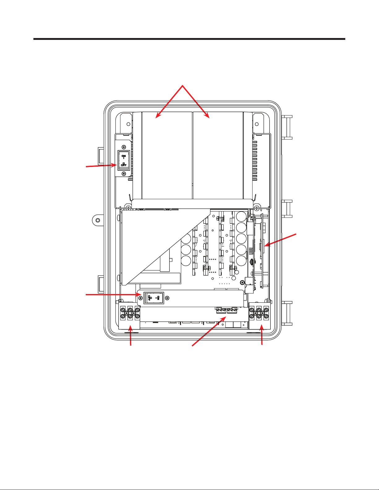
2. General Description
2.1 Overview
Battery
breaker
Batteries
Input circuit
breaker
Input
terminal
block
RS232 connector,
LEDs, and dry contacts
Figure 1 — Alpha Micro Secure
Optional factory
installed Ethernet
card
Output
terminal
block
8
017-220-J0 Rev B
Page 11
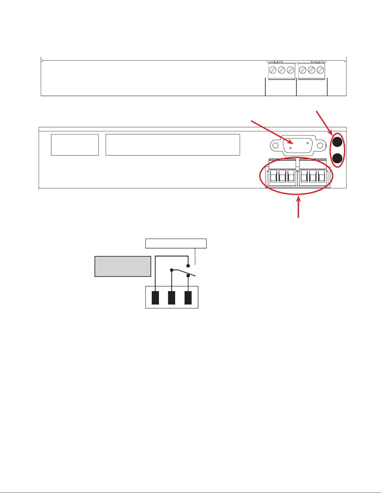
The Alpha Micro Secure has a bar with monitoring LEDs, an RS-232 connector and dry contacts for attachment
of an external monitoring panel.
Dry Contacts
The dry contacts
have a maximum
rating of 1A at 250V.
Normally
Open (NO)
Top view
Bottom View
Microprocessor
Common (C)
RS-232 Connector
UPS
Interior
Normally
Closed (NC)
465
NO NCC
C2
C1
132
NO NCC
Green and Red LEDs
• C1 is the “On Batt” contact,
triggered when the UPS is in
Battery mode and backup battery
power is provided to the load.
• C2 is the “Low Batt” contact,
triggered when the battery voltage
falls below a pre-programmed
setting to indicate the battery is
almost discharged.
• These contacts can be changed
from these factory defaults to
suit your conditions if you have
connected a computer to the unit
017-220-J0 Rev B
Figure 2 — Output Connectors and Monitoring LEDs
9
Page 12

3. Site Planning
WARNING!
The Alpha Micro Secure must be installed in a restricted area accessible only by quali-
ed service personnel.
The Alpha Micro Secure must be correctly grounded for proper operation according to
local and national electrical code.
The utility line attached to the Alpha Micro Secure input MUST be protected by a circuit
breaker certied for this use in accordance with the local electrical code.
The AC input and AC output must each have a disconnect device attached. This device
can be a listed branch circuit protection device or a disconnect switch used on AC Line
only. Neutral or ground must never be disconnected by the user except during installation or maintenance.
3.1 Safety Precautions
• Install the Alpha Micro Secure and batteries in a restricted access location, and on a structure that supports the total weight.
• The input wiring must reach a suitably grounded power outlet and the load wiring must reach the
Alpha Micro Secures output terminal blocks.
3.2 Electromagnetic Compatibility (EMC) Requirements
Observe the following EMC requirements when setting up the Alpha Micro Secure and its internal equipment:
• All AC mains and external supply conductors must be enclosed in a metal conduit or raceway when specified by local, national, and/or other applicable government codes and regulations.
• The customer facilities must provide suitable surge protection.
10
017-220-J0 Rev B
Page 13

4. Unpacking the Alpha Micro Secure
Follow these guidelines for unpacking the Alpha Micro Secure.
WARNING!
The Alpha Micro Secure is heavy, more than 45 kg (100 lb) with batteries. Use proper
lifting techniques. The lifting and moving should be done by at least two people to avoid
injury.
1. Select a suitable area for unpacking.
2. Store all the packing material and boxes for possible equipment returns.
3. Check the contents in your product package. See “Checking the Package Contents” on this page.
4. Compare the packing slip and the list of parts with the items you received. If the list of parts on your packing
slip does not match the items you received, or any items appear damaged, immediately notify your carrier
agent and the supplier who prepared your shipment.
4.2.1 Checking the Package Contents
Before starting the installation, inspect the package contents and make sure the following standard items as well
as purchased options are included.
T able A — Standard Items
Quantity Item
1
1
2
Alpha Micro Secure UPS module.
Alpha Micro Secure Installation & Operation manual.
4 Phillips-head wood screws.
2 or 4 batteries as ordered.
017-220-J0 Rev B
11
Page 14

5. Installation
Once the installation location has been planned and prepared, you are ready to install the Alpha Micro Secure.
There are three steps to setting up the Alpha Micro Secure:
1. Mounting the Alpha Micro Secure
2. Wiring the Alpha Micro Secure
3. Installing and wiring the external batteries
5.1 Transporting and Lifting
WARNING!
To avoid personal injury or damage to the equipment, always use at least two installation personnel to remove the unit from its container.
Batteries must not be installed until the Alpha Micro Secure enclosure has been securely set in place at its permanent location. Transporting the unit with batteries installed
may cause a short circuit, re, explosion, and/or damage to the battery pack, enclosure
and installed equipment. Damage caused by improper shipping or transporting a unit
with batteries installed is not covered by the warranty.
5.2 Mounting Options
Choose any of the following four mounting options:
• Mounting to a wall
• Mounting to a wooden pole
• Mounting to a steel/concrete pole
12
017-220-J0 Rev B
Page 15
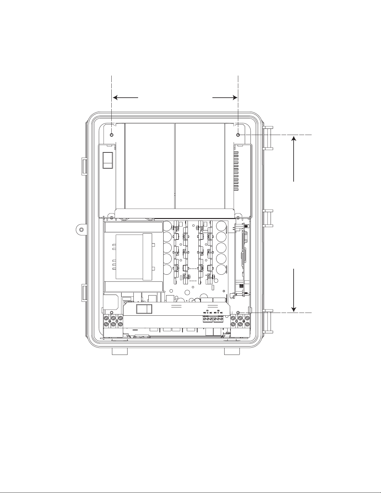
5.2.1 Mounting to a Wall
The Alpha Micro Secure can be mounted to a wall or to wall studs. The wall or studs should be able to hold a
weight of at least 45.0 lbs (20.4 kg) and they must be plumb and the case mounted so it is level.
Using the case as a template, secure the case to the wall with the 4 Phillips-head wood screws supplied with the
unit.
8.0in (20.3cm)
Figure 3 — Wall mounting template
12.0in (30.5cm)
017-220-J0 Rev B
13
Page 16
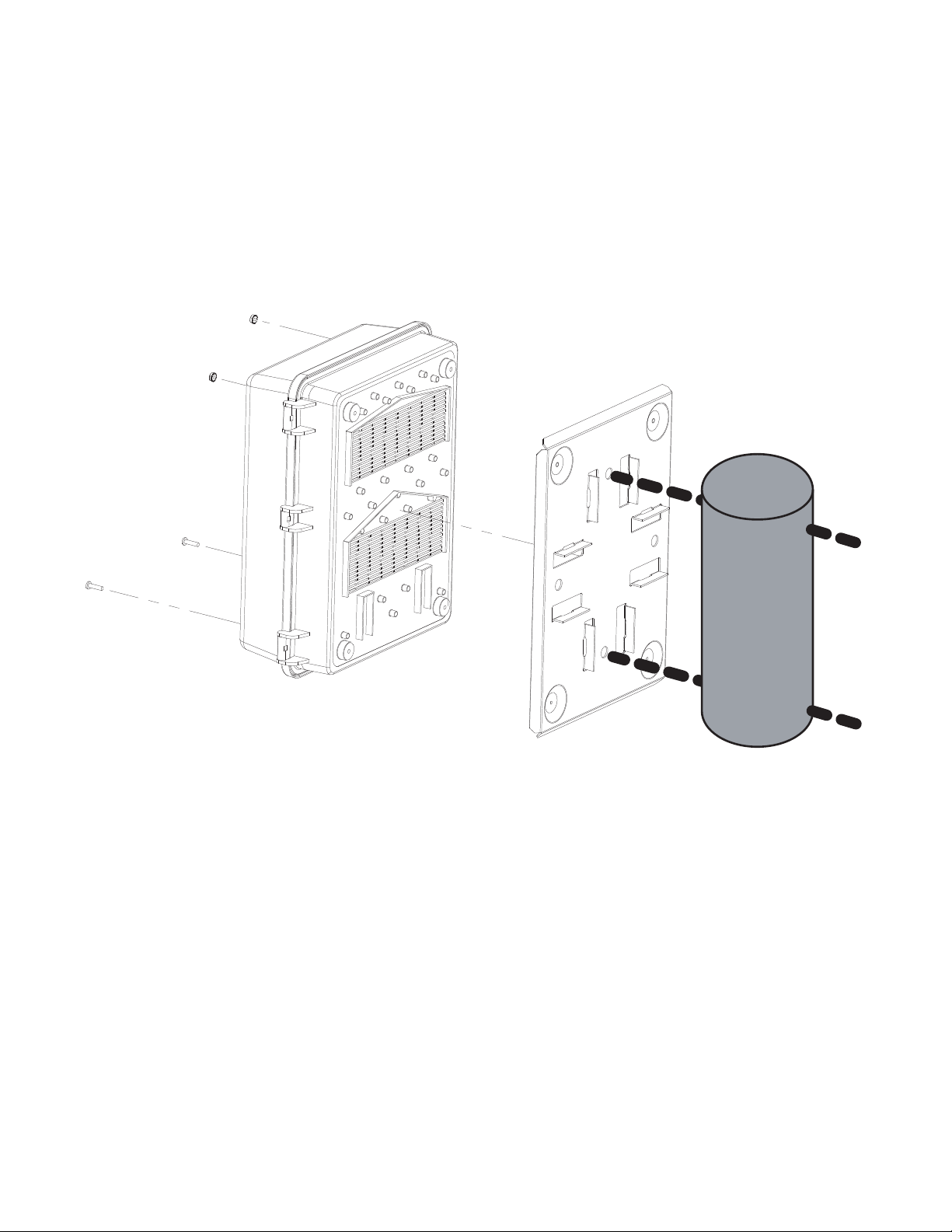
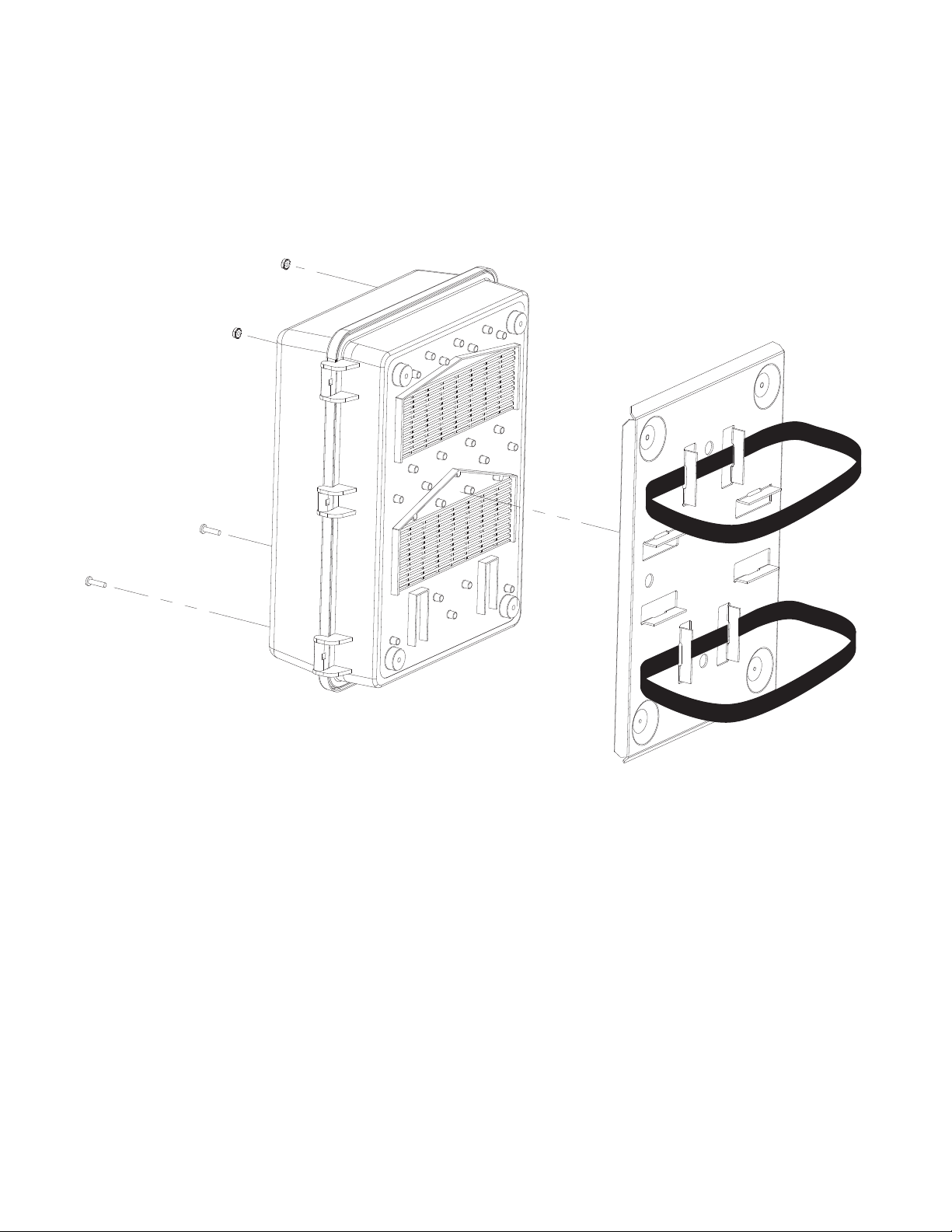
5.2.2 Mounting to a Wooden Pole
The Alpha Micro Secure can be pole mounted with the optional mounting bracket (Alpha Kit# 740-751-21). It allows you to mount to either a vertical or horizontal, steel, concrete or wooden pole.
Procedure
To bolt the UPS to the pole you need the optional mounting bracket and 2, ½" bolts (not provided) to fit the pole.
1. Drill holes into the pole to fit the bolts.
2. Attach the bracket to the pole.
3. Secure the UPS enclosure to the mounting bracket with the 2 mounting screws and 2 nuts provided with the
kit.
14
Figure 4 — Mounting to a wooden pole
017-220-J0 Rev B
Page 17
5.2.3 Mounting to a steel or concrete pole
To strap mount the Alpha Micro Secure to the pole you need the optional mounting bracket and 2, ½" straps
(Band-It #C20499 straps, #C00369 Tool and #C25499 Buckle or equivalent).
1. Attach the straps to the mounting bracket.
2. Attach the bracket to the pole.
3. Secure the UPS enclosure to the mounting bracket with the 2 mounting screws and 2 nuts provided with the
kit.
017-220-J0 Rev B
Figure 5 — Mounting to a steel or concrete pole
15
Page 18
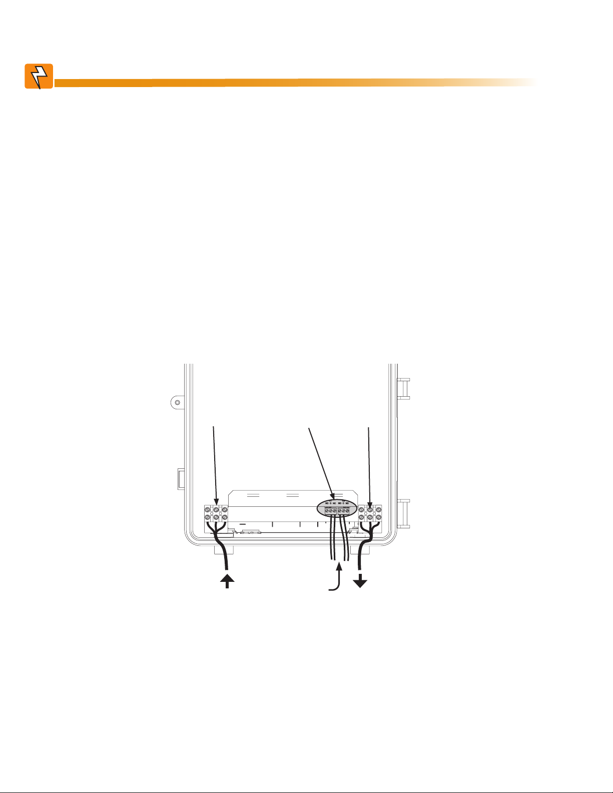
5.3 Wiring the Alpha Micro Secure
WARNING!
Before starting, make sure line power is turned off and the UPS Input breaker and
battery breakers are OFF.
5.3.1 Tools and Materials Required
• Slotted-tip screwdrivers for tightening screws on terminal blocks
• DC voltmeter
• Maximum of 12 AWG wire for wiring the input and output terminal blocks
• If used, maximum of 16 AWG wire for wiring the dry contact terminal blocks
Procedure
You may have to connect the dry contact terminal block outputs and the RS-232 connector depending on your
requirements.
1. Connect the load wiring to the output terminal block as labeled. Torque to 7.0 lb-in (0.8 Nm).
2. If used, connect the dry contact terminal blocks and the RS-232 or Ethernet connectors. If using a conduit,
drill a 1/2" hole to attach a matching conduit.
3. Wire the input terminal block according to its label. Torque to 7.0 lb-in (0.8 Nm).
Input
terminal
3
block
From Line
Power
Dry contact
terminal
block
Drill hole
to attach
incoming
conduit
Output
terminal
1
block
To Load
16
Figure 6 — Wiring the Alpha Micro Secure
017-220-J0 Rev B
Page 19
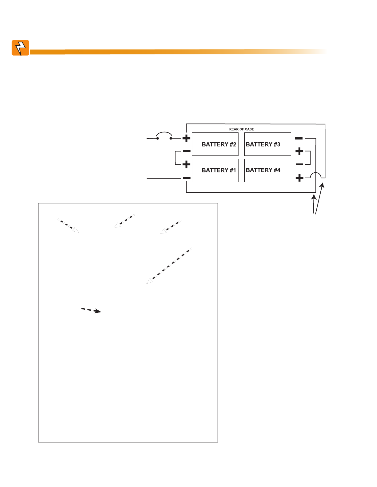
5.4 Installing and Wiring the Batteries
RED
BLACK
WARNING!
Before proceeding, verify the line wire is attached to the line terminal block, the ground
wire is attached to the ground terminal block and the neutral wire is attached to the neutral terminal block to prevent accidental shock or electrocution.
Make sure the battery breaker is OFF before wiring the batteries.
Procedure
1. Install the 4 batteries and wire
them up as shown.
2. Use a DC voltmeter to verify
the battery string’s polarity
and voltage (24Vdc).
Battery breaker
RED
BLACK
Battery #1
Battery
breaker
Battery #2
Battery #3
Battery #4
If using only 2
batteries, ignore
these connections.
017-220-J0 Rev B
Figure 7 — Battery Locations and Wiring
17
Page 20

5.5 Powering Up the Alpha Micro Secure
Make sure that the Line power is qualified but turned off and the batteries are fully charged.
Procedure
1. Turn on the Battery breaker.
2. Switch on the Line power and turn on the Input breaker.
3. Ensure the LEDs are working. See LED status table below.
4. When Line power is first applied, both LEDs illuminate and then only the green light remains on if the UPS is
in Line mode.
Table B — LED status description
LED Status Description
GREEN OFF The UPS inverter is turned off. Line power goes straight to the load.
GREEN ON The UPS is turned on. Line power is provided to the load.
GREEN FLASHING The UPS inverter is on. Backup battery power is provided to the load.
RED ON OR FLASHING The UPS has a malfunction. See the troubleshooting table below.
18
017-220-J0 Rev B
Page 21

6. Operation
The following subsections describe the operation of the Alpha Micro Secure:
• Communicating with the Alpha Micro Secure
• Communicating with the RS-232 interface
• Adjusting and controlling the Alpha Micro Secure
• Viewing the 100-event log
• Communicating with the Alpha UPS Monitor
017-220-J0 Rev B
19
Page 22
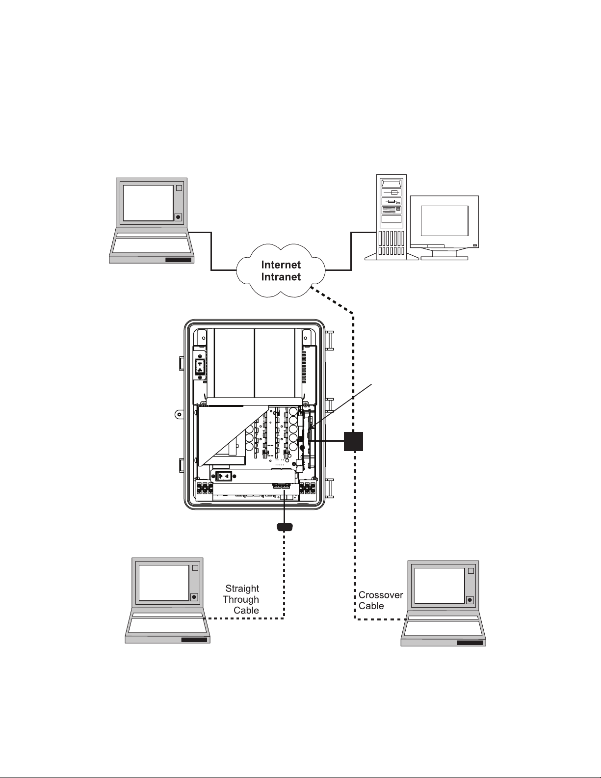
6.1 Communicating with the Alpha Micro Secure
There are several ways you can communicate with the Alpha Micro Secure UPS:
1. Using a RS-232 interface, you can access the UPS command line system with Windows HyperTerminal or
other terminal emulation program.
2. Using a RS-232 serial connection via the Alpha UPS Monitor installed on your computer. The
Alpha UPS Monitor software can be downloaded from www.alpha.ca.
3. Using the optional factory-installed communication module, you can communicate with the
Alpha Micro Secure over a company intranet or the internet using a web browser or with SNMP
communications.
Option 3
Option 3
User’s PC
(Using web browser)
RS-232 Port
SNMP Server
Alpha Micro Secure
with optional Ethernet
Communication Module
installed
Ethernet Port
On-Site Ethernet
Connection
20
Option
1 & 2
User’s PC
(Using Alpha UPS Monitor
available at www.alpha.ca)
Figure 8 — Alpha Micro Secure Communication Options
Option 3
User’s PC
(Using web browser for
ethernet connection
to on-site computer)
017-220-J0 Rev B
Page 23
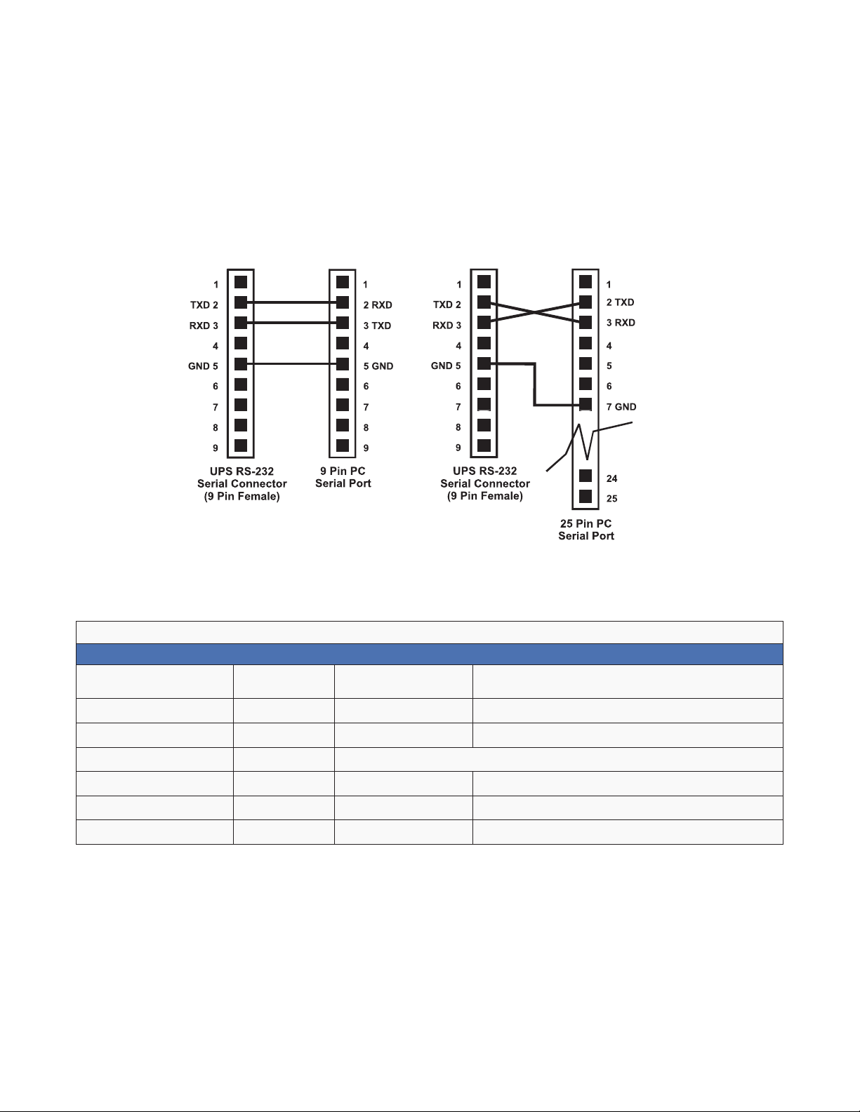
6.2 Communicating with the RS-232 interface
6.2.1 Wiring the RS-232 port
The Alpha Micro Secure’s front panel has a DE-9 female connector. When connected to a PC with Windows
HyperTerminal or other terminal emulation software, the Alpha Micro Secure can be remotely monitored and
controlled with it’s command-line system. The Alpha UPS Monitor provides a Windows or web browser type of
control.
Procedure
1. Connect a 9-pin, fully shielded, straight-through DE-9 to DE-9 connector cable between the computer’s port
and the Alpha Micro Secure’s port.
Figure 9 — RS-232 pin connections
2. Configure the communications parameters to the values shown in the terminal set up table below.
Table C — Terminal Set Up Table
Emulation Type
Duplex Mode Half Duplex Break Length N/A
Xon/Xoff Flow Control None Emulation Type N/A
RTS/CTS Flow Control Off Communication Parameters
Line Wrap On Handshaking Software Handshaking
Screen Scroll On Baud Rate 2400 bps
CR Translation CR Data Format 8-bit Data, No Parity, 1 Stop Bit, No Flow Control.
VT 100 or
Compatible
Backspace N/A
017-220-J0 Rev B
21
Page 24
6.3 Using the Main Menu
The Alpha Micro Secure main menu screen runs on a command line system. This program does not recognize
the backspace or delete keys even if it appears that way on the monitor. If you make a mistake and press Enter,
the Alpha Micro Secure echoes the command back exactly as you typed it. Press Enter and retype the com-
mand again.
If you choose not to use the command line system, you can use the Alpha UPS Monitor to control and monitor the
Alpha Micro Secure
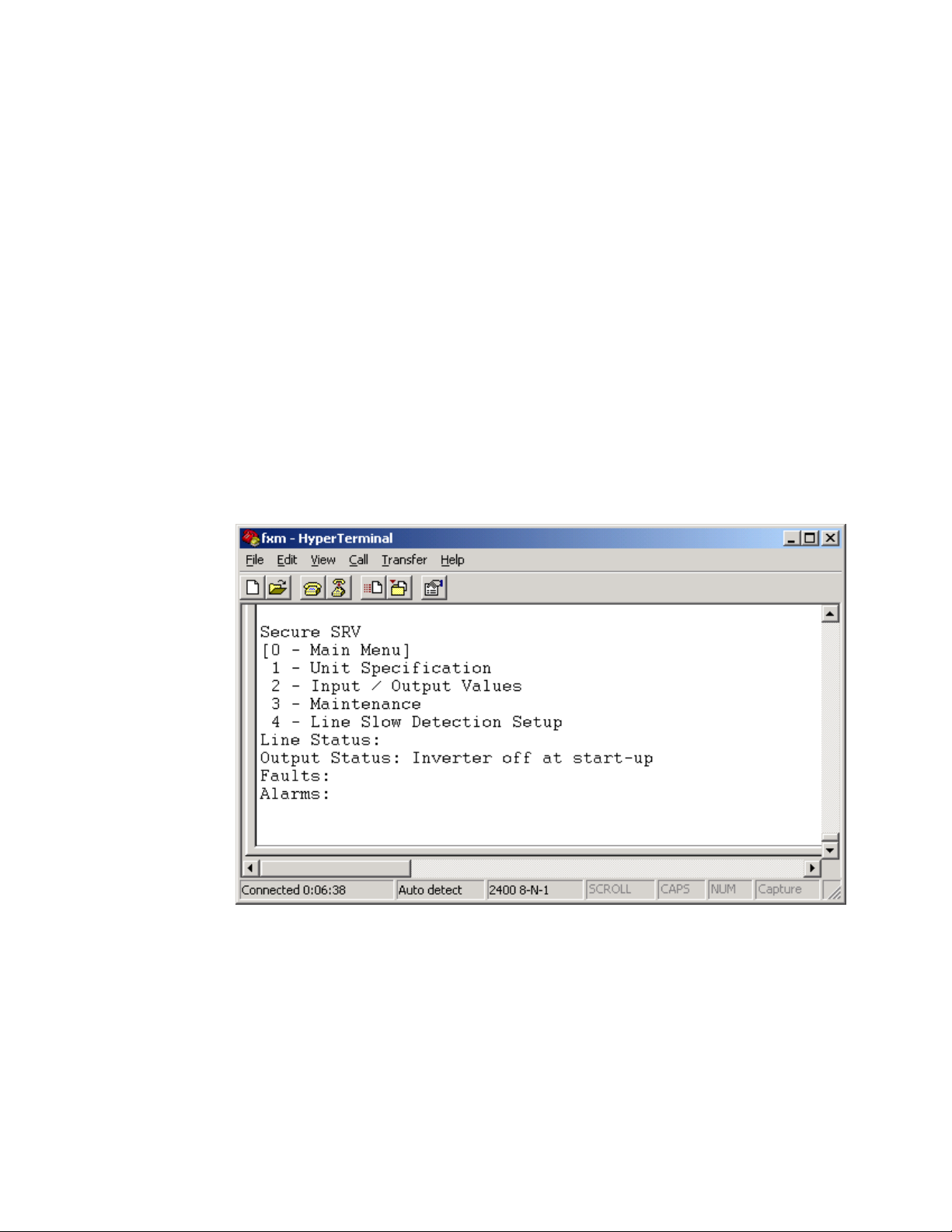
6.3.1 Main Menu Screen
The main menu screen shows the Alpha Micro Secure’s current input and output values, displays if any faults or
alarms are present and gives access to the submenus. It can be accessed from anywhere in the menu tree by
typing 0 and pressing Enter. The Alpha Micro Secure is controlled by submenu 3.
To access a particular submenu, type in the submenu number and press Enter. To update the main menu
screen, press Enter.
The complete menu tree is given in Fig u re 11. Tables describing the Line Status, Output Status, Faults and
Alarms displays are given in Tables G, H, I, and J.
a. The readings on the main menu screen do not automatically update to reflect changes in the
Alpha Micro Secure’s status. Press Enter to update the screen.
b. For many functions you need to enter a password. The factory setting is 1111.
Submenu Numbers
Status, Faults and
Alarms Displays
{
{
Figure 10 — Main Menu Screen
22
017-220-J0 Rev B
Page 25

6.4 RS-232 Menu Tree
Submenus #1, 2 and 4 are read-only screens for monitoring the Alpha Micro Secure To control the
Alpha Micro Secure use submenu #3, the Maintenance submenu.
0-Main Menu
Submenus Submenus
1-Unit Specications
Unit Model
Input
Voltage
Frequency
Output
Voltage
VA
Battery Voltage
Voltage
Software Version
These 2 read-only screens show the Alpha FXM’s
factory specifications or the present input and output
measurements. The Input/Output Values submenu
does not automatically update. For an updated value,
type 2 and press Enter.
Press Enter to go up 1 level in
the menu tree.
To reach any submenu, type
in its number and press Enter.
To reach the main menu, type
0 and press Enter.
2-Input/Output Values
Input
Voltage
Frequency
Output
Voltage
Current
VA
Battery
Voltage
Temperature
3-Maintenance
30-Battery Test Options
300-Set Battery Test Period
301-Battery Test On/Off
31-Inverter On/Off
310-Set Inverter-Off Delay
311-Inverter On/Off
32-Change Password
34-Line Qualify Time
1) Set to 3 seconds (default)
2) Set to 10 seconds
3) Set to 20 seconds
4) Set to 30 seconds
5) Set to 40 seconds
6) Set to 50 seconds
35-Low Battery Warning
Voltage
36-Load Shed Timer
On/Off
1) Timer 1 on
2) Timer 1 off
3) Timer 2 on
4) Timer 2 off
5) Timer 3 on
6) Timer 3 off
4-Line Slow
Detection Setup
This read-only screen shows
the Alpha FXM’s input voltage
parameters. These values
are factory set and cannot
be changed in the field. See
Specifications, “Boost/Buck/
Line Transfer Thresholds.”
017-220-J0 Rev B
Figure 11 — RS-232 Menu Tree
23
Page 26

6.4.1 Line Status
Line status tells you the line’s condition. For an updated value, press Enter.
Table D — Line Status
Normal
Boost
Boost2
Buck
Buck2
Blackout
Freq low
Freq high
The line is within specifications. See specifications, “Boost/Buck/ Line Transfer Thresholds”.
The Alpha Micro Secure is operating in Line mode.
Line voltage is out of tolerance. The Alpha Micro Secure is operating in Boost mode.
Line voltage is out of tolerance. The Alpha Micro Secure is operating in Boost 2 mode.
Line voltage is out of tolerance. The Alpha Micro Secure is operating in Buck mode.
Line voltage is out of tolerance. The Alpha Micro Secure is operating in Buck 2 mode.
The line is absent.
Line frequency is too low.
Line frequency is too high.
6.4.2 Output Status
Output status tells you how the Alpha Micro Secure is producing power. For an updated value, press Enter.
Table E — Output Status
Line mode
Battery mode
Battery mode, low bat. warning
Battery mode (testing battery)
Boost mode
Boost 2 mode
Buck mode
Buck 2 mode
Hot swap mode
Inverter off due to fault
Inverter off due to low battery
Inverter off at start-up
Shutdown due to user request
24
017-220-J0 Rev B
Page 27

6.4.3 Fault and Alarm Displays
Fault and alarm displays any malfunctions the Alpha Micro Secure has encountered. Also see "Troubleshooting".
Table F — Faults
Short_Circuit
Vout_Hi
Batt_Hi
Batt_Lo
Vout_Lo
Overload
Backfeed
Bad_Battery
Temp_Hi
Overload
Temp_Hi
Temp_Lo
User_Input
Line_Freq
No_Temp_Probe
Weak_Battery
Batt_Low
Batt_Brkr_Open
Self_test
Fan_Fail
Wrong_Softwre
The load has a short.
The output voltage is above specifications.
The batteries cannot be charged.
The batteries are almost discharged.
The output voltage is below specifications.
The Alpha Micro Secure is overloaded. Remove excess loads.
A relay inside the Alpha Micro Secure has failed and it cannot be replaced in the field.
Contact Alpha Technologies customer service department.
The battery voltage has dropped below a specified level. Inverter shuts down.
The Alpha Micro Secure is operating above temperature range.
Table G — Alarms
The Alpha Micro Secure is overloaded. Switch off excess loads.
The ambient battery temperature is too high.
The ambient battery temperature is too low.
The user input contact "User Input: S2" is shorted.
The line frequency is outside of the Alpha Micro Secure’s input specifications.
The battery temperature sensor has become disconnected or has failed.
The battery has failed the background scan in Line mode.
The battery voltage is low.
The battery breaker is opened.
The Alpha Micro Secure is performing self test.
The Alpha Micro Secure internal fan has failed.
The Alpha UPS Monitor is invalid (either version or part number).
017-220-J0 Rev B
25
Page 28

6.4.4 Adjusting and Controlling the Alpha Micro Secure
The Maintenance submenu lets you control the Alpha Micro Secure and change selected items to meet your
operational needs.
Procedure
From the Main menu, type 3 and press Enter.
Table H — Maintenance Submenu
30 Battery Test Options
31 Inverter On/Off
32 Change Password
34 Line Qualify Time
35 Low Battery Warning
Voltage
36 Load Shed Timer On/Off
This starts the battery test and sets how long the test will run. The default setting for the
test duration is 2 minutes, but this can be adjusted in 1 minute intervals. See "Operating
the Alpha Micro Secure, BATT TEST”.
This switches the inverter on or off to allow you to prevent a damaging deep battery
discharge or to provide backup battery power to the load. See “Operating the
Alpha Micro Secure INVERTER”.
You can set a delay before the inverter switches off to allow time for switching off critical
loads. The Set Inverter ON/OFF delay is only available when the Alpha Micro Secure is in
the Battery or Standby modes.
The delay can be adjusted in 1 second steps with a default setting of 0 seconds to a
maximum of 600 seconds (10 minutes). The delay is only available in the Standby or
Battery modes. Once the Alpha Micro Secure returns to the Line mode, the delay resets
itself to 0 seconds.
This changes the Alpha Micro Secure’s password. The factory set password is 1111,
which can only be changed when the Alpha Micro Secure is in Line mode. The password
is limited to 4 alpha-numeric characters in length.
This lets you set the delay when the Alpha Micro Secure goes from Battery mode to
Line mode after the line becomes requalified. The purpose of this delay is to make sure
the line is stable before the Alpha Micro Secure switches back to it. See “Operating the
Alpha Micro Secure, QUAL TIME”.
The default setting is 3 seconds, but you can set this to 3, 10, 20, 30, 40 or 50 seconds.
The lets you set the Alpha Micro Secure’s low battery warning voltage, adjusting the
setting to match the batteries you are using and the actual operating conditions.
The default value is 40% (47 Vdc) and can be adjusted in 1% (0.05 Vdc) increments
between 45.0 (0 %) and 50.0 Vdc (100%) by typing in the % battery voltage level where
you want the warning to be triggered.
This lets you switch the timer contacts on or off. See "Contacts C1 to C6”.
26
017-220-J0 Rev B
Page 29

6.4.5 Programming the Dry Contacts and the Clock
On the Alpha Micro Secure front panel. contacts (C1 to C6) can be programmed to meet your specifications with
RS–232 communications. You can also adjust the Alpha Micro Secure date and time.
Programming the Dry Contacts
The functions of dry contacts C1 to C5 (and if factory configured, dry contact C6) can be changed with RS-232
communications.
For example, to change contact C1:
1. To see how it is currently programmed, type c1 (all lower case) and press Enter.
2. The Alpha Micro Secure responds with *c1=1 where the * shows the unit responded to your command.
For example: a "1" shows it is programmed to be the On Battery indicator as shown in the Dry Contact
Configuration table below.
Table I — Dry Contact Conguration
1= On Battery 4= Alarm 7= Timer 2
2= Low Battery 5= Fault 8= Timer 3
3= Timer 1 6= Disabled
3. To change the contact, type c1=X where X is 1 to 8 and press Enter.
The Alpha Micro Secure responds with *c1=(1 to 8). The programming is done for that contact. Repeat as
necessary for the other contacts.
Each contact can only be programmed for one function at a time and cannot show multiple conditions.
4. To reset the contacts to the factory default, type default and press Enter. The Alpha Micro Secure responds
with *default, showing it is reset. This command also resets the timer setting to the 2 hours factory default.
See “Setting the Timer Contact”. See "9. Specifications" on page 68 for the factory default settings of dry
contacts C1 to C6.
017-220-J0 Rev B
27
Page 30

6.4.6 Setting the Timer Contact
The front panel’s timer contact can be programmed to suit your application. See "Contacts C1 to C6” and "Programming the Dry Contacts and the Clock". The table below explains how.
Table J — Setting the Timer Contact
Enter command UPS display Description
timer and press Enter *timer=02:00:00 Returns the value of timer
timer1 and press Enter *timer1=02:00:00 Returns the value of timer1
timer
Displaying the
Setting the timer
Note: In the above example, the default timer setting of 2 hours is used.
* Indicates that the Alpha Micro Secure has responded to the command you entered.
† Time can be entered in units of 0.5 second; e.g. 120 units of 0.5 seconds = 60 seconds. However, it is more intuitive to enter time in the hh:mm:ss format, such as 00:01:00 for 1 minute or 60 seconds in the above example.
timer2 and press Enter *timer2=02:00:00 Returns the value of timer2
timer=00:01:00 and press
Enter
timer=00:01:00 and press
Enter
timer1=00:01:00 and press
Enter
timer1=120
timer2=00:01:00 and press
Enter
timer2=120
default and press Enter *default
†
and press Enter *timer1=120
†
and press Enter *timer2=120
*timer=00:01:00
*timer=120
*timer1=00:01:00
*timer2=00:01:00
Sets the value of timer1 to 60
seconds.
Sets the value of timer1 to 60
seconds.
Sets the value of timer2 to 60
seconds.
Resets the timer to the factory
default of 02:00:00 (2 hours);
and resets contacts C1 to C5 to
the factory default settings.See
“Programming the Dry Contacts”.
28
017-220-J0 Rev B
Page 31

6.4.7 Setting the Date and Time
Table K — Setting the Date and Time
Enter command UPS display Description
Returns the current date and
clock and press Enter *clock=12/31/ 07 22:00:00
clock=010107 120000 and
press Enter *clock= 01/01/ 07 12:00: 0 0
Notes:
1. Time is displayed in the 24 hours clock format.
2. Changing the mm/dd/yy format with DATE SEL on the LCD Control menu does not change
the RS-232 mm/dd/yy format.
3. If the Alpha Micro Secure has been in storage or switched off for a prolonged period, the
backup Lithium coin battery could be drained and may not correctly keep a backup of the
date and time you entered. After switching on the Alpha Micro Secure check the date and
time settings. The Alpha Micro Secure should display the current date and time. If it displays
the date as "00:01:00", then the battery is spent and you need to ask a qualified service
personnel to replace the lithium coin battery. See "Troubleshooting".
* Indicates that the Alpha Micro Secure has responded to the command you entered.
† If the date or time change is invalid, the Alpha Micro Secure will return the time and date it
was set to before you tried making the change. The date and time must be entered as one complete line command. You cannot change only the time or the date alone. Both must be set at the
same time. If you make a mistake, press Enter and try again.
time.
Sets the date and time to Jan
†
01, 2007, 12:00 pm.
017-220-J0 Rev B
29
Page 32

6.4.8 Viewing the Serial Number
To display the serial number of the Alpha Micro Secure UPS, type "∗QY0" at the command line and press "Enter".
6.4.9 Setting the Peukert Number and Capacity
You can set the Peukert Number and Capacity using the RS-232 interface or the web interface. To display the
current Peukert Number, type "∗QY6" at the command line and press "Enter".
To change the Peukert Number to 1.1345, type "∗ST6:1.1345" at the command line and press "Enter".
To display the current Peukert Capacity, type "∗QY7" at the command line and press "Enter".
To change the Peukert Capacity to 109.123, type "∗ST7:109.123" at the command line and press "Enter".
To determine the Peukert number and capacity of your battery, refer to "Puekert Number and Battery Capacity".
30
017-220-J0 Rev B
Page 33

6.4.10 100-Event Log
Up to 100 events are stored in the Alpha Micro Secure’s log. If more than 100 events occur, the oldest is overwritten.
Procedure
1. To see the log, type event (all lower case) and press Enter. The events are listed starting with the most
recent and appear as: If less than 100 events occurred, the last entry will appear as:
eventX=12/25/99 01:45:59 0000000000000000, 0000000000000000, 000
Event Date Time Alarm Fault Mode
Date & Time formats depend
on selected display format
Alarm: When the following bits show a 1,
the following alarms are displayed.
Self Test
Code Mode Code Mode Code Mode
000 Standby 003 Boost 1 006 Inverter
001 Line 004 Buck 1 009 Shutdown
002 Boost 2 005 Buck 2 010 Bypass
See below for details on these
readouts.
Fault: When the following bits show a 1,
the following faults are displayed..
Table L — Event Codes
2. If less than 100 events occurred, the last entry will appear as:
eventX=00/00/00 00:00:00 0000000000000000, 0000000000000000, 000
3. To clear the log, type eventclr and press Enter. It takes the Alpha Micro Secure 30 seconds to clear the log.
Do not enter any other commands during this time.
4. To see a specific event, type eventX where X is from 1 to 100 and press Enter. To see a range of events (for
example, events 20 to 30), type eventX-X where X are events from 1 to 100 and press Enter.
017-220-J0 Rev B
31
Page 34

6.4.11 Communicating with the Alpha UPS Monitor
Introduction
The Alpha UPS Monitor graphical user interface (GUI) provides web or Windows© like computer communications with the Alpha Micro Secure The screen and its features are shown below. It is used to monitor, control and
set various parameters like the date and time, determine when to perform the weekly self test, change the relay
configurations, etc. The Fault or Alarm indicators show if the Alpha Micro Secure has experienced a malfunction
and the cause. Descriptions of all the screens and their functions are given in “Operation”.
E
B
A
F
C
D
32
Figure 12 — Alpha UPS Monitor (UPS Specification Screen shown)
A Screen selection menus.
B Current UPS operating mode. This is updated automatically.
Fault and alarm indicators – when a light in this bar is illuminated, move the mouse
C
cursor over the light to determine the malfunction. Double-clicking on the light will
send you to the Alarms & Faults screen.
D Readout screens.
E Drop-down menus.
F Online indicator.
017-220-J0 Rev B
Page 35

6.4.12 Checking Your Windows Computer for the .NET Framework
1. Click on the Start button.
2. Go to and click on Settings.
3. Click on Control Panel.
4. Double-click on the Add or Remove Programs icon.
5. When the window shown in the figure below appears, scroll through the list of applications. If you
see Microsoft .NET Framework listed, the Framework is already installed and you can install the
Alpha UPS Monitor. If you don’t see it listed, you MUST install it from the Microsoft Windows update web site
before installing the software.
Figure 13 — Add or Remove Programs Window
If you are downloading from Microsoft’s web site, an Internet web browser such as Internet Explorer or Firefox
must be installed on your computer. In addition to installing .NET, downloading from the web site will update your
computer with all the latest security updates. If your computer is part of a company network, check with your
network administrator before downloading software from the Internet.
017-220-J0 Rev B
33
Page 36

6.4.13 Installation and Set Up
The following tools and materials are required:
• Alpha UPS Monitor, available for download from www.alpha.ca.
• Windows 2000 or later with Microsoft .NET framework installed.
• DE–9 serial straight-through computer cable.
Procedure
1. Install the Alpha UPS Monitor onto your computer. Restart the computer.
If you install the Alpha UPS Monitor on a version of Windows without the .NET framework installed, an error message saying the framework is not installed will appear. Install the framework onto your computer according to
"6.4.11 Communicating with the Alpha UPS Monitor" on page 32. Restart your computer and then try to install
the Alpha UPS Monitor again.
2. Connect the computer cable from any available communications port on the computer to the RS–232 port on
the Alpha Micro Secure front panel. See "6.2.1 Wiring the RS-232 port" on page 21.
3. Set the communications parameters on your computer to:
a. COM Port: The COM port on your computer you have selected to use.
b. Baud Rate: 2400.
4. To start communications between the computer and the Alpha Micro Secure do one of the following:
a. Click on the screen’s Online Indicator, or
b. In the File drop-down menu, click on Connect to Alpha Micro Secure
If the computer cannot connect to the Alpha Micro Secure a pop up screen appears asking you to check the wiring and that you are connected to the proper com port.
34
017-220-J0 Rev B
Page 37

6.5 Operation
The various screens are described on the following pages and operate like Web or Windows-type screens. Point
and click to change the various functions or fields.
The on line indicator shows if you are connected to the Alpha Micro Secure The Alpha UPS Monitor automatically
polls the Alpha Micro Secure to obtain its status. The default setting is polling once every 3 seconds, but you can
change this in the UPS Maintenance-Unit Configuration screen in the “Status Refresh Time” menu.
If a light or lights are illuminated in the Fault or Alarm fields, the Alpha Micro Secure has a malfunction. Hover your
mouse cursor over the light to learn the type of malfunction or double-click on it to go straight to the Alarms &
Faults screen.
To control the unit or change it’s settings or parameters, either click on the On/Off buttons, or choose an item
from a drop down menu. Then click on the Update Settings button.
If you do not click on this button, the change will not happen.
6.5.1 UPS Specifications
This screen displays the various specifications of the Alpha Micro Secure
017-220-J0 Rev B
Figure 14 — Alpha UPS Monitor: UPS Specification screen
35
Page 38

6.5.2 UPS Monitoring
These read-only screens show the Alpha Micro Secure’s current input and output values and other measurements.
Input & Output
Shows the current line input and Alpha Micro Secure output values and the Alpha Micro Secure’s present operating mode.
Figure 15 — UPS Monitoring: Input & Output screen
Battery & Inverter
Shows the battery string’s status and how many times and for how long the inverter has been active.
36
Figure 16 — UPS Monitoring: Battery & Inverter screen
017-220-J0 Rev B
Page 39

Relay & Load Shed
Shows how the front panel dry contacts are configured. If any relays are used for load shedding, the time setting
is shown.
Figure 17 — UPS Monitoring: Relay & Load Shed screen
User Input Status
Shows the current status of the user programmable inputs 1 to 3.
Figure 18 — UPS Monitoring: User Input Status screen
017-220-J0 Rev B
37
Page 40

6.5.3 UPS Maintenance
The UPS Maintenance screens are used to configure and adjust the Alpha Micro Secure to meet your operating
needs. To change parameters, either click on the On/Off buttons or choose an item from a drop down menu. To
execute the changes, click on the Update Settings button. If you do not click this button, the changes will not
happen.
Unit Configuration
Is used to set the name, input, output and how often the GUI polls the Alpha Micro Secure
Figure 19 — UPS Maintenance: Unit Configuration screen
Battery
Allows adjustments of battery string voltage, charging parameters, low battery warning time, periodic self test
time, and starts the self test.
38
Figure 20 — UPS Maintenance: Battery screen
017-220-J0 Rev B
Page 41

An accurate battery runtime estimation requires the following parameter to be adjusted:
• Peukert Number: Refer to the appendix for information about how to calculate the Peukert number to be
entered here.
• Battery Capacity: This is the rated capacity (Ah) of the battery shown on the battery data sheet. Do not con-
fuse the battery capacity with the Peukert capacity.
• Battery Open Circuit Voltage: This number is obtained from the battery data sheet. The battery data sheet
shows the value for a single battery, so for a 48 V system where 4 batteries are connected in series, this number must be multiplied by four.
The "Battery Runtime Remaining" algorithm attempts to calculate the health of the battery to get a more accurate
prediction of the remaining battery runtime. An accurate estimate of the battery health requires that at least one
battery discharge greater than 20% depth of discharge has taken place since the unit was switched on. When the
unit is powered up from an off state, the algorithm assumes that a new battery is connected to the unit. Each discharge of greater than 20% will result in a new calculation for the relative battery health. This value is then used
in the "Battery Runtime Prediction algorithm to compensate for an aging battery. We recommend that the user set
up a periodic (every 6 months) battery test with a depth of discharge of at least 20%.
The "Battery Runtime Remaining" algorithm relies heavily on the battery voltage to predict the remaining runtime.
This results in a less accurate predicted runtime during periods when the battery voltage is changing rapidly. The
battery voltage typically changes rapidly during the first few minutes of discharge when the unit switches from
charging to discharging while the unit is in the Inverter mode. The battery voltage may also change rapidly during
the last 20% of the discharge time when the battery is almost drained.
Inverter
Is used to turn the inverter on or off to start or stop backup battery power to the load.
Figure 21 — UPS Maintenance: Inverter screen
017-220-J0 Rev B
39
Page 42

Relay & Load Shed
Is used to configure the front panel’s dry contact to provide a signal for turning off the load.
Figure 22 — UPS Maintenance: Relay & Load Shed screen
Controlling the external fan by temperature triggered dry contact
The Alpha Micro Secure has up to 6 dry contacts (C1 to C6) on the front panel which can be configured by the
user to open or close based on the specific trigger conditions. Dry contact functions currently available include:
Alarm, Fault, Timer, Low Battery, On Battery, etc. The Temperature trigger has been added as a new function,
with a user configurable range of +20°C to +55°C. When the battery temperature (monitored by the Battery Temperature Probe) reaches the threshold, the assigned relay closes and turns on the external fan.
Dry contact C6 is by default factory hard wired to External Vdc. To configure C6 as a programmable dry contact,
the unit must be sent back to the factory.
The Temperature trigger can be programmed via one of the following 3 interfaces:
1. LCD panel – from the Logo screen, navigate to Control Menu > RELAY TEMP. Press the SELECT button
and the current temperature display will start flashing. Use the Scroll button to change the temperature in
5°C increments. Press SELECT to accept the changes or CANCEL to abort.
RELAY TEMP
55
40
120/60/N
LINE
017-220-J0 Rev B
Page 43

Dry contact functions are not programmable through the LCD. Use the RS-232 GUI or the HyperTerminal instead.
2. RS-232 GUI – Figure 24a shows the Relay Configuration window under the UPS Maintenance > Relay &
Load Shed screen. As an example, to assign C1 as the Temperature trigger, select Temperature from the
drop down menu. Click Update Configuration and the current status will update momentarily. In the example
shown below, the fan on temperature threshold is set at 55°C. To change this value, simply type the new
value into the Fan On Temperature box (or use the up/down arrow keys) and click Update Configuration to
update the current status display.
a. Assigning the Temperature trigger function to a dry contact.
b. Setting the Temperature trigger value.
017-220-J0 Rev B
Figure 23 — Temperature trigger function via Alpha UPS Monitor
41
Page 44

3. RS-232 HyperTerminal – the Temperature trigger function can be assigned to any available dry contacts as
Inverter
mode
entered
Dry contact
activates when timer
counts down to zero
Timer
starts to
count down
Microprocessor
described in "Programming the Dry Contacts" (e.g. c1=11, where 11 is the assigned index for the Temperature
trigger function.)
After establishing an RS-232 connection with the Alpha Micro Secure at the HyperTerminal screen prompt,
type Temp and press Enter to display the current temperature setting Alpha Micro Secure returns *temp=20).
To change the value to +35°C, type temp=35 and press Enter. The Alpha Micro Secure returns *temp=35 as
confirmation.
Figure 24 — Temperature trigger function via HyperTerminal
Programmable Dry Contact Time of Day Action
You can assign a dedicated timer to a dry contact. Upon entering the Inverter operating mode, the timer is activated and begins to count down from a user defined value. When the timer reaches zero, the programmed dry
contact relay will be activated (Status = ON).
42
Figure 25 — Programmable Timer Operation
017-220-J0 Rev B
Page 45

A typical application of this timer controlled dry contact function is to control a traffic light. When the grid power
Inverter
mode
entered
Dry contact activates
when enabled timer
counts down to zero
Timer starts to
count down
if enabled
Microprocessor
Real time clock
Peak period
settings
Disable Timer (Action=ON) or
Enable Timer (Action=OFF)
fails, the Alpha Micro Secure goes into the Inverter mode and continues supplying backup power to the traffic light. Since the batteries supplying the backup power have limited capacity, a timer controlled dry contact
is usually configured to switch the traffic light into the flashing amber or flashing red mode after a user-defined
period to conserve battery power. This setup works fine during non rush hour traffic, but during rush hour, it may
be more desirable to keep the traffic light running normally for as long as backup power is available. To address
this issue, a new feature called the Time of Day Action has been added to deactivate the timer during a user
defined time period up to twice each day.
Figure 26 — Time Of Day Action Operation
You can define up to 2 peak time periods of the day:
1. Go to the UPS Maintenance > Relay & Load Shed screen.
2. In the Time of Day Action Configuration dialogue box, set up the start and end time of the first rush hour
under Time Period 1 and the second rush hour under Time Period 2. In this example, during the first time
period (7 AM to 9 AM), all 3 timers are disabled (they do not count down at all). Similarly, all timers are
disabled during the second time period (3 PM to 6 PM).
3. Select ON under each time period. Click the Update button under each time period to store the settings.
Confirm your settings in the UPS Monitoring > Relay & Load Shed > Time of Day Action Status screen.
017-220-J0 Rev B
Figure 27 — Time Of Day Configuration
43
Page 46

Figure 28 — Time Of Day Action Status
Once the Time of Day Action is configured, the Alpha Micro Secure will automatically disable the timers during
the Inverter mode at the defined peak periods.
You can switch off the Time of Day Action by setting one or both time period(s) to OFF. The dry contact will be
activated by the timer regardless of the peak period settings.
Time & Date
Is used to set the Alpha FXM’s date and time.
44
Figure 29 — UPS Maintenance: Time & Date screen
017-220-J0 Rev B
Page 47

Password
Is used to set the Alpha Micro Secure’s password. The factory set password is 1111.
Figure 30 — UPS Maintenance: Password screen
The password is limited to 4 alphanumeric characters. The software will not accept more than 4 characters.
User Input
Three programmable User Inputs exist. Their functions are similar to the Dry Contact relays. Supported functions
include: (a) Shutdown, (b) User Alarm and (c) Self Test.
Figure 31 — UPS Maintenance: User Input screen
Any user input can be configured to perform a certain action in response to different trigger types and logic levels. For example, if you want the Alpha Micro Secure to issue an intrusion alarm when the door is opened, you will
need to wire the door with a switch that triggers a user input every time the door is opened. The following procedure describes how User Input 1 can be configured as an intrusion alarm input.
017-220-J0 Rev B
45
Page 48

Procedure
1. Select UPS Maintenance > User Input to display the User Input Configuration window.
Figure 32 — User Input Configuration: Setting the Trigger Type
2. In the Input 1 column, select the Type down arrow to display the 3 types of available triggers: Edge Trigger,
Level Toggle, and Level Alternative. For more information on how triggers work, see "Types of Trigger".
3. Select Edge Trigger.
4. Select Low from the Level drop down menu. The User Input will go to logic level "low" whenever it is
triggered.
Figure 33 — User Input Configuration: Setting the Logic Level
5. Select User Alarm On from the Action #1 drop down menu.
Figure 34 — User Input Configuration: Setting an Action
6. Click the Update button and enter the password to confirm if required.
46
017-220-J0 Rev B
Page 49

7. Check the User Input Current Status at the UPS Monitoring > User Input Status page.
Figure 35 — User Input Current Status
Perform a quick test by shorting the User Input 1 dry contact pin (Pin 19 of C6) to ground (Pin 22 of C6) with a
short length of PVC insulated electronic wire. This will trigger the Alpha Micro Secure to issue a User Input Alarm
as shown below.
Figure 36 — User Input Current Status
Hovering the cursor over the amber indicator will display the corresponding context sensitive message.
017-220-J0 Rev B
47
Page 50

Operation
Many of the screens used for Ethernet communications look and function the same and contain the same information as the Alpha UPS Monitor screens. There are additional screens only available with Ethernet communications which are detailed below.
Configure Site Information
This screen is used to enter site location information into the UPS’s memory.
Figure 37 — Alpha UPS Monitor: Configure Site Information
Communications
• Configure TCP/IP is used to set the UPS’s IP or TCP address.
• Configure SNMP is used to set the UPS for use with SNMP communications.
• Configure RS-232: You cannot change RS-232 parameters with this screen.
• Email Notification tells the card to send an e-mail message whenever selected UPS events happen.
48
Figure 38 — Alpha UPS Monitor: UPS Communications screen
017-220-J0 Rev B
Page 51

Restoring All Parameters to Default Values
The purpose of this command is to reset the Alpha Micro Secure to the factory default state. See Table P for a list
of parameters that will be restored to their default values.
CAUTION!
This command resets all parameters that are user-congurable. All previously programmed operation will be lost. Implement a backup plan for mission critical operations. This command is password protected.
The default command can be issued via the RS-232 HyperTerminal or the RS-232 GUI as follows:
• RS-232 HyperTerminal – type default:all and press Enter. Enter the password and the Alpha Micro Secure
returns *default as confirmation.
• RS-232 GUI – From the UPS Maintenance > Unit Configuration screen, click the Restore Defaults button.
Enter the password to execute the command.
017-220-J0 Rev B
Figure 39 — Restore all default commands
49
Page 52

Table M — List of Parameters
Maximum battery charging current
Temperature compensation of battery charging
Maximum allowable duration of output short circuit before shutdown
Property settings of programmable user input #1
Action #1 setting of programmable user input #1
Action #2 setting of programmable user input #1
Property settings of programmable user input #2
Action #1 setting of programmable user input #2
Action #2 setting of programmable user input #2
Property settings of programmable user input #3
Action #1 setting of programmable user input #3
Action #2 setting of programmable user input #3
Start hour of rush hour of time of day action period #1
Start minute of rush hour of time of day action period #1
End hour of rush hour of time of day action period #1
End minute of rush hour of time of day action period #1
Start hour of rush hour of time of day action period #2
Start minute of rush hour of time of day action period #2
End hour of rush hour of time of day action period #2
End minute of rush hour of time of day action period #2
Scheduled events
Format setting of date display on LCD
Line qualify time
Time setting of periodical self-test (minute) (hh:mm)
Inverter off delay setting
RS-232 baud rate
Number of weeks setting of periodical self-test
Day of the week setting of periodical self-test
Time of the day setting of periodical self-test
Battery low warning threshold setting (%)
Self test duration setting (minutes)
Internal temperature setting to turn on cooling fan
Load shed timer1 duration
Load shed timer2 duration
Load shed timer3 duration
Programmable dry contact #1 setting
Programmable dry contact #2 setting
Programmable dry contact #3 setting
Programmable dry contact #4 setting
Programmable dry contact #5 setting
Programmable dry contact #6 setting
Password setting
50
017-220-J0 Rev B
Page 53

Alarms & Faults
This read-only screen shows the operating status of the Alpha Micro Secure When the fault or alarm indicators on
the horizontal bar are illuminated, place the mouse cursor over the light to display the context sensitive message.
Figure 41 — Alpha UPS Monitor: UPS Alarms & Faults screen
Event History
This screen shows the last 100 events recorded by the Alpha Micro Secure Choosing a number in the Event
Index drop-down box and then clicking on the View Selected button will display the updated information about
the selected event.
017-220-J0 Rev B
Figure 40 — Alpha UPS Monitor: UPS Event History screen
51
Page 54

To view all the events, click on the View All button to open the Event Log Monitor window. Clicking on the Clear
History button clears the log. This action cannot be undone.
Figure 42 — Alpha UPS Monitor: Event Log Monitor screen
In the Event Log Monitor window, the events are displayed by date and time. Scroll up and down the list to
select the events you want to see. To download the latest events from the Alpha Micro Secure click on the Get
Events button. This process may take a few minutes. When the process is finished the events can be saved to an
event file by selecting File > Save As.
To build a complete history of events for an Alpha Micro Secure save all the downloaded events from the unit to
the same event file. A maximum of 100 events can be stored on the Alpha Micro Secure The oldest events are
replaced by the newest ones. However, saving to the same event file gives the option of appending to an existing
event file when selecting File > Save As.
Figure 43 — Event Log Monitor, Open Event File window
To view a previously saved event log without downloading any new events from the Alpha Micro Secure and over-
writing the saved event file, select File > Open and navigate to the saved event log file.
When opening or saving event log files, only files with the extension 'evt' can be opened or closed. This is the file
type associated with event log files in the Alpha UPS Monitor.
52
017-220-J0 Rev B
Page 55

Upgrade Files
This feature is available only on Alpha Micro Secure UPS equipped with the network interface card factory option.
To upgrade the Alpha UPS Monitor firmware, browse to the .bin file and click OK to start the upload. This may
take a few minutes to complete.
Figure 44 — Alpha UPS Monitor: Upgrade Firmware
To upgrade the Communication module, browse to the .ezip file and click OK to start the upload. This may take a
few minutes to complete.
Figure 45 — Alpha UPS Monitor: Upgrade Communication Module
Communications
This screen changes the Alpha Micro Secure's communication parameters. The RS-232 Baud Rate cannot be
changed.
Figure 46 — Alpha UPS Monitor: UPS Communications screen
017-220-J0 Rev B
53
Page 56

Keep Alive
The Keep Alive feature can be used to reset power when a communication failure is detected. The purpose of
the reset is to temporarily remove power and reset the local communications equipment powered by this unit.
The goal of the Keep Alive feature is to attempt to restore communications by resetting the local communication
equipment until communications is re-established
54
017-220-J0 Rev B
Page 57

Keep Alive status/manual control:
a. The Status field allows the user to enable or disable the Keep Alive function. When disabled the alarm is
cleared.
b. The Delay to Startup field allows the user to set the time to the first ping from the enable ping or UPS
restart after a ping failure. Minimum = 5 s, Maximum = 3600 s.
Keep Alive Method to detect communication failure:
a. The Protocol field allows Ping as the only option.
b. The IP Address field is used to enter the IP address to be pinged.
c. The Delay Between Retry field is the delay between pings. Minimum = 5 s, Maximum = 65535 s.
How to detect communication failure:
a. The Timeout field is where the ping time out setting is configured. Minimum = 2 s, Maximum = 65534 s.
b. The Retries Before Failure field is the number of pings to repeat before power cycling. Minimum = 1,
Maximum = 20.
Keep Alive action to attempt to restore communication:
a. The Action field allows Reset Power as the only option.
b. The Action Duration field is how long the output will be shut off by the UPS, Minimum = 1, s
Maximum = 3600 s.
When To Fail:
a. The After X Consecutive Actions field determines the number of times the UPS will go through the ping
and power down and back up cycle before registering an Alarm for Keep Alive. Other alarms and events
will occur regardless of this value. After the final power cycle, the UPS will issue another ping after the
Delay between retry has elapsed. This ensures the destination IP is not alive. The UPS will then set the
Keep Alive alarm. Minimum = 1, Maximum = 20.
Keep Alive Failure:
a. The Send Trap field allows the email and SNMP trap notification to be switched on and off for the Keep
Alive only.
b. The Delay to Re-Startup field configures the delay after the Keep Alive alarm is set and the next ping is
sent in delay to restart. Minimum = 5 s, Maximum = 3600 s.
017-220-J0 Rev B
55
Page 58

6.6 Communicating Via The Intranet or Internet
If the Alpha Micro Secure is equipped with the optional, factory-installed communication module, then the
internet or a company intranet can be used to communicate with the Alpha Micro Secure In addition, the
Alpha Micro Secure can be monitored and controlled via a web browser or with SNMP protocols.
6.6.1 Installation and Set Up
The following tools and materials are needed:
• Computer with network card and web browser.
• Cross over cable or hub.
• The UPS Final IP Address and Subnet Mask and if needed the Default Gateway and the DNS Server ad-
dresses.
CAUTION!
To successfully complete this procedure, you should have a working knowledge of
network protocols and how to congure them. Consult your network administrator for
details.
If multiple UPS’s are installed on the same network, congure each unit’s IP address
before the installation. Each UPS on the network MUST have its own unique IP address
See "Communications, Congure TCP/IP".
6.6.2 Procedure
1. Connect the Alpha Micro Secure to the computer with either the cross over cable or a hub.
2. Switch on the computer.
3. Configure the network card to talk to the communication module. The module’s default address is
http://192.168.0.90.
4. Type the IP address into the browser and press ENTER. The input and output screen appears. See "6.5.2
UPS Monitoring" on page 36.
5. Go to the communications screen, Configure TCP/IP, and configure the TCP/IP properties according to your
network requirements. Push the Apply Settings button. The screen will prompt for the password. The factory
defa u lt pa ss w or d is 1111.
6. Connect the Alpha Micro Secure to the configured network according to your new properties.
7. Access the Alpha Micro Secure according to the new network properties.
56
017-220-J0 Rev B
Page 59

6.6.3 Types of Trigger
There are 3 types of trigger:
Edge trigger
When the user input changes from one state to the other, the Alpha Micro Secure is triggered to perform Action
#1. If the level is set to High, the action will be triggered by a Low to High edge (leading edge). If the level is set
to Low, the action will be triggered by the High to Low edge (falling edge).
Action #1 Action #1
User input
(a) Level = High
User Input = Low to High, Action #1 is triggered
User Input = High to Low, no action triggered
Low to High
edge trigger
User input
(b) Level = Low
User Input = High to Low, Action #1 is triggered
User Input = Low to High, no action triggered
High to Low
edge trigger
Action #1 Action #1
Figure 47 — Edge Trigger
Level Toggle
When the Level is set to High, the Alpha Micro Secure is triggered to perform the other action when the user
input changes from Low to High. If the input then changes from High to Low, Action #2 will be triggered. In other
words, a level change in the user input will trigger an action toggle between Action #1 and #2.
Action #1 Action #1
User input
(a) Level = High
User Input = Low to High, Action #1 is triggered
User Input = High to Low, Action #2 is triggered
Action #2 Action #2
017-220-J0 Rev B
Action #2Action #2
User input
Action #1 Action #1
(b) Level = Low
User Input = High to Low, Action #1 is triggered
User Input = Low to High, Action #2 is triggered
Figure 48 — Level T rigger
57
Page 60

Level Alternative
When the level is set to High, the Alpha Micro Secure is triggered to perform the next action when the user input
changes from Low to High. If the input then changes from High to Low, no action will be triggered because the
level is set to High. In other words, only a Low to High user input level triggers an action when Level is set to
High. Similarly, when Level is set to Low, the Alpha Micro Secure will trigger an action only with a High to Low
user input.
Action #1
User input
User Input = Low to High, Action #1 is triggered
User Input = High to Low, no action triggered
User Input = Low to High, Action #2 is triggered
User Input = High to Low, no action triggered
User input
Action #1 Action #2 Action #1
User Input = High to Low, Action #1 is triggered
User Input = Low to High, no action triggered
User Input = High to Low, Action #2 is triggered
User Input = Low to High, no action triggered
Figure 49 — Level Alternative
Action #2 Action #1
58
017-220-J0 Rev B
Page 61

7. Maintenance
7.1 Updating the Micro Secure Firmware (with Communication Module)
If your Alpha Micro Secure is provided with the factory-installed communication module, the firmware upgrade
can be done via an intranet or internet connection.
• Before you begin, download the latest version of firmware to your computer from www.alpha.ca.
CAUTION!
Upgrade Ethernet card rst, if applicable, and then FXM software.
7.1.1 Communication module
To upgrade the Communication module, browse to the .ezip file and click OK to start the upload. This may take a
few minutes to complete.
017-220-J0 Rev B
Figure 50 — Upgrade Communication Module
59
Page 62

To upgrade the FXM firmware, browse to the .fbin or .bin file and click Send File to start the upload. This may
take a few minutes to complete.
Figure 51 — Upgrade Firmware
7.2 Updating the Micro Secure Firmware (no Communication Module)
Material Required
• Laptop with a DB-9 COM Port
Before Upgrading
• Install the FXMProgrammer software onto the laptop.
• Copy the upgrade firmware file (.sx or .fbin files) to a folder on the laptop.
Procedure
1. Pull out the battery fuse on the Micro Secure 100.
2. Turn off the AC input to the Micro Secure 100.
3. Short Jumper JP1 on the RS-232 board.
60
JP1
017-220-J0 Rev B
Page 63

4. Connect the DB-9 to DB-9 cable between the Micro Secure and the laptop.
5. Install the battery fuse.
6. Start the FXMProgrammer software.
7. Select a COM port from the drop down list of available ports.
View available serial ports with
Serial Ports -> Refresh
Ports refreshes COM
ports in the drop down
box top right)
Serial Ports -> List Ports
Displays the software
version currently
installed on the FXM
Displays the software
version about to be
installed on the FXM.
8. Click on Open File to browse to the software file location (only .sx or .fbin files are supported)
017-220-J0 Rev B
61
Page 64

9. Click on Apply the update to the FXM unit.
10. Watch the progress bar and the Programming Messages window. (If there is a connection or any other kind
of error, click on Apply the update again.)
The Micro Secure will reset automatically once the upgrade is finished.
11. Close the FXMProgrammer software.
12. Remove the battery fuse.
13. Remove the Jumper on JP1.
14. Install the battery fuse.
15. Connect the AC input to the Micro Secure.
Contact Alpha Technologies’ Technical Support at 1-800-667-8743 if you have any questions on this procedure.
62
017-220-J0 Rev B
Page 65

7.3 Testing and Replacing the Batteries
7.3.1 Battery life
Batteries lose their ability to store power as they age. Regularly test the batteries to ensure that they can continue
providing reliable service. Battery life is reduced by three major factors:
• Temperature – higher ambient temperatures, especially above 25°C, will reduce battery life. For example,
an average operating temperature of 27°C will likely reduce the life of the battery by 25%. Ensure that the
Alpha Micro Secure and batteries are situated in a well ventilated area with adequate temperature control. A
cool environment is preferable.
• Number of discharge cycles – the more frequent the batteries are discharged, the shorter the battery life.
Frequent power outages imply the need for more frequent battery replacement.
• Depth of discharge – the longer the batteries are required to provide back up power, the shorter the battery
life. Frequent full discharging and the associated recharging of the batteries reduces the life. Shut down the
electrical load or return to primary power as soon as possible to extend the battery life.
7.3.2 Battery Run Time
The chart below shows typical run times (time to full discharge) for the standard batteries supplied with this unit.
These runtimes are for batteries in new and good condition. The run time performance will deteriorate over time in
a progressively decreasing curve.
Discharge Rate Characteristics
Battery Voltage (V)
100%
Load
50%
Load
Discharge Time
Figure 52 — Typical Discharge Characteristics for Lead Acid Batteries
017-220-J0 Rev B
63
Page 66

7.3.3 Battery Maintenance
The batteries supplied with this unit are sealed and maintenance free. Regularly ensure that all connectors are
tight and free of corrosion. The presence of corrosion, swelling of the battery case, or distortion in the shape of
the case suggests that the batteries need to be replaced.
7.3.4 Battery Conductance Test (Optional)
1. Place the conductance meter probes across Battery #1.
2. Record the voltage and Siemens values in a log book.
3. Repeat for batteries #2, #3 and #4.
A new AlphaCell 180GXL battery has a conductance reference value of 1100 Siemens at 25°C. When this value
drops to 550 Siemens or 50% of the new battery reference value, the battery capacity is suspect of being below
80% and should be evaluated further. When the temperature of the batteries is not between 20°C and 30°C, use
the following temperature compensation values.
Table N — Battery Temperature Compensation Values
Battery Temperature Reference Value New 180GXL Suspect Value
35°C or higher 1183 592
30°C 1140 570
25°C 1100 550
20°C 1063 532
15°C 1028 514
10°C 995 498
5°C 965 483
0°C or colder 936 468
7.3.5 Replacing the Batteries
Replace the batteries according to the results of the self test or the presence of terminal corrosion, swelling of
the battery case, or distortion in the shape of the case. New batteries will normally provide longer run times than
older ones. Larger capacity batteries may be available. Contact Alpha Technical Support (1 888 462 7487) to
order replacement batteries or to obtain assistance. On-site service may be available in your area.
Tools and Materials Required
• AC/DC voltmeter or multimeter.
• Labels or masking tape and marker.
• Torque wrench.
• Slot head screwdriver to fit the terminal blocks.
• High strength, flame-proof tape such as duct tape.
• Battery terminal corrosion inhibitor (such as NOCO Company’s NCP-2 or Sanchem Inc.’s No-Ox ID Grease
“A”).
64
017-220-J0 Rev B
Page 67

WARNING!
Read and understand the battery safety instructions in “Product Safety Information”.
CAUTION!
Make sure all the replacement batteries are of the same type and rating. Failure to do so
could result in improper charging and damage to the batteries.
The Alpha Micro Secure cannot provide backup battery power while the batteries are being replaced. If the line
becomes unqualified while the batteries are being replaced, the Alpha Micro Secure shuts down and no power is
provided to the load.
Procedure
1. The Alpha Micro Secure must be in the Line state. If it isn’t, wait until the line is qualified before proceeding.
2. Switch the Alpha Micro Secure into the Bypass State by doing one of the following:
a. From the Logo Screen, press the SELECT button once, the LCD shows CONTROL.
Press the SELECT button once, the LCD shows INVERTER.
Press the SCROLL button once until the LCD shows INV BYPASS.
Press the SELECT button once, OFF is flashing.
Press the SCROLL button once, ON is flashing.
Press the SELECT button once, ON is solid.
b. From the Alpha UPS Monitor main screen, go to the UPS Maintenance > Unit Configuration screen.
Switch on the Bypass Mode by clicking the ON button and then the Update Configuration button. The
Alpha Micro Secure responds by displaying a “Bypass State” alarm. This is normal and does not indicate
a problem. It will clear itself when the Bypass state is subsequently disabled.
3. Switch off the battery circuit breaker.
4. Replace the batteries.
5. Switch on the battery circuit breaker.
6. Switch the Alpha Micro Secure out of the Bypass state by switching the Bypass Mode OF F.
017-220-J0 Rev B
65
Page 68

7.4 Preventative Maintenance
Perform preventative maintenance on the Alpha Micro Secure module every 6 to 12 months. For mission critical
applications such as backup traffic intersections, more frequent maintenance should be done. Proper implementation of the following procedure will insure that your system continues to provide reliable backup power in the
event of a utility power failure.
7.4.1 Tools and Materials Required
• Wrench set.
• Labels and marker to number batteries.
• Conductance meter for optional conductance test.
7.4.2 Procedure
1. Inspect the Alpha Micro Secure and wiring for any physical damage. Repair or replace as required.
2. Verify that all connections are securely fastened. Tighten if necessary.
3. Inspect the batteries for cracks or swelling. Replace all four batteries if any of the batteries are cracked or
swollen. Replace only a faulty battery if an Alphaguard battery balancer is installed.
4. Inspect the battery terminals for corrosions. Clean and apply a corrosion prevention compound such as
NOCO Company NCP-2 or Sanchem Inc. NO-OX-ID if required.
5. Re-tighten the battery terminal bolts on Insert Terminal batteries. Re-torque the battery terminal bolts on Flag
Terminal batteries to the manufacturers specifications on if required.
6. Label the batteries #1, #2, #3 and #4. The battery negative cable from the Alpha Micro Secure is connected
to Battery #1, and the battery positive cable from the Alpha Micro Secure is connected to Battery #4.
7. Verify that the battery temperature probe is securely taped to the side of either battery #2 or #3.
7.4.3 Operational Test
1. Activate the Alpha Micro Secure self-test function.
2. After passing the self-test, disconnect the AC input to the Alpha Micro Secure to trigger the unit into the
backup (Inverter) mode.
3. Let the Alpha Micro Secure operate in the backup mode for approximately 10 minutes.
4. Measure the individual battery voltages while the Alpha Micro Secure is operating in the backup mode.
There should be no more than 0.6 volts difference between the highest battery voltage and the lowest battery
voltage.
CAUTION!
A battery that measures 2 V lower than the other three batteries in the string probably
has a shorted cell. Replace all four batteries.
Three batteries in the string measuring the same voltage and one battery measuring
several volts higher indicates an open cell in the battery with the higher reading. Replace all four batteries.
5. Verify that there is no Low Battery Alarm.
6. Reconnect the AC input.
66
017-220-J0 Rev B
Page 69

8. Troubleshooting
Table O — Troubleshooting Guide
Symptom Action
Is utility power connected?
No output power
No battery backup power
No power to load
If you have the RS-232 computer communication enabled, then you can perform additional
troubleshooting. See “Communicating with the RS-232 interface”, “Using the Main Menu”, and
“Communicating with the Alpha UPS Monitor".
Is the battery breaker tripped?
Are the batteries discharged?
Is the input circuit breaker open?
Is the battery breaker tripped?
Are the batteries discharged?
Is the UPS’s output properly connected to the load?
Is the battery breaker tripped and is the utility power connected to
UPS input connector?
017-220-J0 Rev B
67
Page 70

9. Specifications
Table P — Mechanical Specications
Parameter Value
Dimensions H x W x D
mm (in)
Weight without batteries kg (lb) 50 (22.7) with 4 batteries
Mounting
Humidity
Temperature, °C
Operating
Storage
Altitude, m (ft)
Operating
Storage
AC input and output connectors 3-position terminal block (maximum 10 AWG)
Std: 15 (381) x 12 (305) x 6 (153)
25 (11.3) without batteries
Wall or pole (with optional bracket Alpha Kit# 740-751-21)
Operating: non-condensing up to 95%
Storage: up to 95%
–40 to 122 (–40 to 50)
–40 to 167 (–40 to 75)
Up to 3700 (12,000)
Up to 4600 (15,000)
Dry contact ATC connectors Terminal block, mating plug JITE p/n PTB750B-03-1-03-3 or equivalent (max 16
RS-232 connector
Ethernet connector
Dry contacts Two programmable dry, single pole double-throw relays. Contacts are rated at
Displays Two LEDs (1 red and 1 green) via communication board.
AWG).
DE-9, female
Optional, factory installed RJ-45.
120Vac, 1A. The factory default settings are: C1: On battery, C2: Low battery
68
017-220-J0 Rev B
Page 71

Input
Table Q — Electrical Specications
Parameter Value
Voltage (nominal), Vac
Frequency, Hz, ±5%
Input circuit breaker 3.0A, 125Vac
Output
Voltage (nominal), Vac
Auxiliary, Vac
Frequency, Hz, ±5%
Power, W/VA
Load Crest Factor
Output Voltage Distortion
Normal Mode
Backup (Inverter) Mode
Transfer Time, ms
AVR to Backup
Backup to AVR
Line Qualication Time, s
Battery String Voltage
Battery Charger Current
(Factory default, A)
Battery Charger Temperature
Compensation
Battery size Standard: 4 x 9 AHr
Other
Battery circuit breaker 15A
120 or 230 (optional 220).
60/50 (auto-frequency).
Current, A 2.0 @ 120Vac
Current, A
Waveform
Efciency
1.0 @ 220/230Vac
1.5A, 230Vac
120 or 230 ± 10%
24, –5% to +20%
60/50 (auto-frequency).
4.20 @ 24Vac
0.83 @ 120Vac
0.43 @ 230Vac
100 total including auxiliary output
Sine wave
3:1 (load dependent)
< 3% THD (resistive load)
> 85%
> 75%
5 (Typical)
3 (Typical)
3
24
3
-5mV / °C / Cell (factory default), user adjustable to -2.5, -4, -5 and -6mV / °C / Cell
via RS-232 connection.
017-220-J0 Rev B
69
Page 72

Table R — Regulatory
Parameter Value
Electrical Safety
Emission
Marks
Packaging
UL 1778, CSA 107.1, EN 50091-1-2, EN60950.
FCC Part 15, Subpart B, Class A, CSPR22, EN55022 Level A.
CSA US, CE (230 Vac versions only).
C
Designed to meet requirements for ISTA program.
Radio Frequencies
The Alpha Micro Secure generates, uses and radiates radio frequencies if not installed and tested in
accordance with the instructions in this manual. It has been tested and found to comply with the limits
established for a Class A computing device pursuant to part 15 of FCC rules and CISPR 22 when it is
operated alone. It also complies with the radio interference regulations of DOC which are designed to
provide reasonable protection against such interference to radio to TV reception, which is determined
by switching it on and off, relocate the equipment or use an electrical circuit other than the one used by
the Alpha Micro Secure.
70
017-220-J0 Rev B
Page 73

10. Peukert Number and Battery Capacity
10.1 Introduction
The Alpha Micro Secure series UPS units run on batteries when the AC utility power fails. In this mode, the user
may want to estimate the remaining time that UPS batteries can supply power to the loads.
The battery run time remaining is calculated based on the Peukert equation. Two critical parameters are required
for the equation:
• Peukert number.
• Peukert capacity.
The Peukert number and Peukert capacity depend on the battery characteristics. This document describes the
procedures to determine the Peukert number, and Peukert capacity for the selected battery.
Once the Peukert number and capacity are determined, enter these values in the GUI or web interface. The
Alpha Micro Secure will report the remaining battery run time.
The Peukert equation and the remaining battery run time are estimates only. The actual run time may vary based
on various parameters like the age and status of the batteries etc.
10.2 Determining the Peukert Number and Peukert Capacity
1. Obtain the data sheet of the selected battery.
2. Calculate the nominal load current for the application.
Example: If the load is 150 W and the battery string is 24Vdc, the load current is calculated as 150W / 24V =
6.25A.
3. Find the current discharge ratings table in the data sheet. From the table, pick two current discharge values
(I1 and I2) that are closest to the calculated load current and look up the two discharge hours (R1 and R2).
4. Use the following formula to calculate Peukerts number and capacity:
Peukert’s number = n =
(Log (I
Peukert’s capacity = (I1)n x R
Log (R
per battery
1
)
2/R1
) - Log (I2))
1
(1)
(2)
10.3 Determining Peukert Capacity for Series Parallel Combinations
1. For batteries connected in series, the Peukert’s capacity for the battery bank is given by the equation:
Peukert’s capacity
2. For batteries connected in parallel, the Peukert’s capacity for the battery bank is given by the equation:
Battery bank
= Peukert’s capacity
(as calculated in equation (2))
per battery
Ah
017-220-J0 Rev B
Peukert’s capacity
Battery bank
= Peukert’s capacity
(where N = number of batteries in parallel)
per battery
x N Ah
71
Page 74

10.4 Example
(1)
Peukert’s number = n =
Log (R
2/R1
)
(Log (I
1
) - Log (I2))
(1)
(2)
The following example shows how to calculate Peukert number and capacity from a configured battery string.
Consider four Alpha 195GXL batteries connected and configured as shown in the figure below. Two of the four
batteries are connected in series, and the two series strings are connected in parallel to the 24Vdc output.
+
24 VDC
▬
+
+ +
▬ ▬
195 GXL
12 VDC
▬ ▬
195 GXL
12 VDC
Figure 53 — Battery string example
+
195 GXL
12 VDC
195 GXL
12 VDC
The Peukert number and capacity for the above configuration can be determined as follows:
1. Obtain the data sheet of the selected battery. See table below.
2. Find the current discharge ratings table in the data sheet. From the table, pick two current discharge values
(I1 and I2) that are closest to the calculated load current value. Look up the two discharge hours (R1 and R2).
3. From the table, I1 = 13.9A, I2 = 10.8A, R1 = 6 hrs, R2 = 8 hrs.
From Equation (1) earlier:
From Equation (2) earlier
4. The Peukert’s capacity for the series combination (Batteries #1 and #2) is 166.00 Ah.
5. The Peukert’s capacity for the parallel combination (Batteries #1, #2 and #3, #4) is 2 x 166.00 Ah = 332.00 Ah.
72
Peukert’s number = n =
n = = 1.14
Log (8/6)
Log (13.9) - Log (10.8)
Peukert’s capacity = (I1)n x R
= 15.2
1.217
x 6
= 166.00 Ah per battery
Log (R
(Log (I
1
)
2/R1
) - Log (I2))
1
per battery
017-220-J0 Rev B
Page 75

10.5 Using the Spreadsheet
Download the spreadsheet “Peukert’s Parameters Calculator.xls” from www.alpha.ca website.
Enter the Baery
voltage and
nominal load
From the data sheet of
the baeries enter the
}
2 closest currents and
discharge hours
Enter the
number of
parallel strings
017-220-J0 Rev B
73
Page 76

11. Warranty
Alpha Technologies Ltd. warrants all equipment manufactured by it to be free from defects in parts and labor, for
a period of two years from the date of shipment from the factory. The warranty provides for repairing, replacing
or issuing credit (at Alpha’s discretion) for any equipment manufactured by it and returned by the customer to
the factory or other authorized location during the warranty period. There are limitations to this warranty coverage. The warranty does not provide to the customer or other parties any remedies other than the above. It does
not provide coverage for any loss of profits, loss of use, costs for removal or installation of defective equipment,
damages or consequential damages based upon equipment failure during or after the warranty period. No other
obligations are expressed or implied. Warranty also does not cover damage or equipment failure due to cause(s)
external to the unit including, but not limited to, environmental conditions, water damage, power surges or any
other external influence.
The customer is responsible for all shipping and handling charges. Where products are covered under warranty
Alpha will pay the cost of shipping the repaired or replacement unit back to the customer.
11.1 Battery Warranty
Note that battery warranty terms and conditions vary by battery and by intended use. The most common battery
warranty provided by Alpha is a two year full replacement warranty with a pro-rated warranty for the following
three years. Pro rated warranty provides a credit applicable toward the purchase of new batteries from Alpha. The
credit is calculated as the purchase price multiplied by the percentage of the battery life that was not available (in
months). Battery warranty coverage is lost where the battery charge is not maintained for 6 months. Contact your
Alpha sales representative or the Technical Support team at the above number to understand your entitlements
under Battery Warranty.
74
017-220-J0 Rev B
Page 77

12. Emergency Shutdown Procedure
The Alpha Micro Secure UPS contains more than one live circuit. In an emergency, line power may be disconnected at the UPS’s input, but AC power can still be present at the output.
1. Switch OFF the input circuit breaker.
2. Switch OFF the battery circuit breaker.
3. Disconnect the AC input power.
4. Disconnect the internal battery string.
Complete the following for your records:
Serial #
Options
Purchase Date
This unit was purchased from:
Dealer
City
State/Province
Zip/ Postal Code
Country
Telephone #
Fax #
E Mail Address
017-220-J0 Rev B
75
Page 78

Page 79

Page 80

Alpha Technologies Ltd.
7700 Riverfront Gate
Burnaby, BC V5J 5M4
Canada
Tel: +1 604 436 5900
Fax: +1 604 436 1233
Toll Free: +1 800 667 8743
Alpha Energy,
Alpha Technologies Inc.
3767 Alpha Way
Bellingham, WA 98226
United States
Tel: +1 360 647 2360
Fax: +1 360 671 4936
Alpha Industrial Power Inc.
1075 Satellite Blvd NW,
Suite 400
Suwanee, GA 30024
United States
Tel: +1 678 475 3995
Fax: +1 678 584 9259
Outback Power
5917 195th St NE,
Arlington, WA 98223
United States
Tel: +1 360 435 6030
Fax: +1 360 435 6019
Alpha Technologies Europe Ltd.
Twyford House Thorley
Bishop’s Stortford
Hertfordshire, CM22 7PA
United Kingdom
Tel: +44 1279 501110
Fax: +44 1279 659870
Alpha Technologies
Suite 1903, 191F., Tower 1,
33 Canton Rd. Tsim Sha Tsui
China, Hong Kong City,
Kowloon, Hong Kong
Tel: +852 2736 8663
Fax: +852 2199 7988
Alpha Technologies GmbH
Hansastrasse 8
D-91126
Schwabach, Germany
Tel: +49 9122 79889 0
Fax: +49 9122 79889 21
Alphatec Ltd.
339 St. Andrews St.
Suite 101 Andrea Chambers
P.O. Box 56468
3307 Limassol, Cyprus
Tel: +357 25 375 675
Fax: +357 25 359 595
Alpha Innovations Brasil
Rua Manuel Augusto
de Alvarenga, 155
São Paulo, SP - Brasil
Tel: +55 11 2476 0150
Fax: +55 11 2476 0150
For technical support, contact Alpha Technologies:
Canada and USA: 1-888-462-7487
International: +1-604-436-5547
Alpha Technologies S.A.
131 Boulevard de l’Europe
1301 Wavre
Belgium
Tel: +32 10 438 510
Fax: +32 10 438 213
Alpha TEK ooo
Khokhlovskiy Pereulok 16
Stroenie 1, Office 403
Moscow, 109028
Russia
Tel: +7 495 916 1854
Fax: +7 495 916 1349
Alphatec Baltic
S. Konarskio Street 49-201
Vilnius, LT-03123
Lithuania
Tel: +370 5 210 5291
Fax: +370 5 210 5292
Visit us at www.alpha.ca
Due to continuing product development, Alpha Technologies reserves the right to change specifications without notice.
Copyright © 2014 Alpha Technologies. All Rights Reserved. Alpha® is a registered trademark of Alpha Technologies.
 Loading...