

Page 1
LPE Enclosure
Installation and Operation Manual
LPE Enclosure
Effective: 05/2010
member of The Group
™
Page 2

Alpha Technologies
Power
®
Page 3

LPE Enclosure
Installation and Operation Manual
031-302-B0-001, Rev. A
Effective Date: May 2010
Copyright© 2010
Alpha Technologies, Inc.
member of The Group
NOTE:
Alpha denies responsibility for any damage or injury involving its enclosures, power supplies, generators,
batteries or other hardware, manufactured by Alpha or members of the Alpha Group, when used for an
unintended purpose, installed or operated in an unapproved manner, or improperly maintained.
NOTE:
Photographs and drawings contained in this manual are only for illustrative purposes. These photographs and
drawings my not exactly match your installation.
NOTE:
Review the written and illustrative information contained in this manual before proceeding. If there are
questions regarding the safe installation or operation of this product, please contact Alpha Technologies or
your nearest Alpha representative.
™
Contacting Alpha Technologies: www.alpha.com
For general product information and customer service (7 AM to 5 PM, Pacic Time), call
031-302-B0-001 Rev A
or
1-800-863-3930
For complete technical support, call
1-800-863-3364
7 AM to 5 PM, Pacic Time or 24/7 emergency support
3
Page 4

Table of Contents
Safety Notes .......................................................................................................................... 5
1.0 Introduction ................................................................................................................. 9
1.1 LPE Enclosures ............................................................................................... 9
1.2 LPE Specications and Options..................................................................... 10
2.0 Installation..................................................................................................................11
2.1 Enclosure Installation, Wall-mount ..................................................................11
2.2 Enclosure Installation, Steel or Concrete Pole............................................... 12
2.3 Enclosure Installation, Ground-mount............................................................ 13
2.3.1 Pre-installation .................................................................................... 13
2.3.2 Enclosure Grounding: Ground-mount ................................................ 15
2.3.3 Ground-mount Installation ................................................................... 16
2.4 Dimensions .................................................................................................... 18
2.5 Connecting Utility Power ................................................................................ 19
2.5.1 Service Power ..................................................................................... 20
2.5.2 Connecting Coaxial Cable................................................................... 22
2.6 Battery Installation ......................................................................................... 25
2.6.1 Battery Terminal Connections ............................................................. 27
2.7 Power Supply Installation............................................................................... 28
3.0 LPE Enclosure Maintenance .................................................................................... 29
List of Figures
Fig. 1-1, LPE Enclosure.................................................................................................................................... 9
Fig. 2-1, Mounting Bracket ..............................................................................................................................11
Fig. 2-2, Ground-mount Positioning and Safety ............................................................................................. 14
Fig. 2-3, Suggested Grounding Method ......................................................................................................... 15
Fig. 2-4, LPE Enclosure Pedestal................................................................................................................... 17
Fig. 2-5, Location of (3) Knockouts for Enclosure-to-Pedestal Mounting ....................................................... 17
Fig. 2-6, 120Vac Service Entrance Wiring ...................................................................................................... 20
Fig. 2-7, 520-R Receptacle Wiring ................................................................................................................. 21
Fig. 2-8, SPI and SPI RF Mounting Locations ................................................................................................ 24
Fig. 2-9, Battery Identication Label ............................................................................................................... 25
Fig. 2-10, Hardware stack-up, Threaded Battery insert .................................................................................... 27
Fig. 2-11, Hardware stack-up, Threaded Battery Insert with optional in-line fuse ............................................ 27
4
031-302-B0-001 Rev A
Page 5

Safety Notes
Review the drawings and illustrations contained in this manual before proceeding. If there are any questions
regarding the safe installation or operation of the system, contact Alpha Technologies or the nearest Alpha
representative. Save this document for future reference.
To reduce the risk of injury or death, and to ensure the continued safe operation of this product, the following
symbols have been placed throughout this manual. Where these symbols appear, use extra care and
attention.
ATTENTION
The use of ATTENTION indicates specic regulatory/code requirements that may affect the placement of
equipment and /or installation procedures.
NOTE:
A NOTE provides additional information to help complete a specic task or procedure.
CAUTION!
The use of CAUTION indicates safety information intended to PREVENT DAMAGE to material or
equipment.
WARNING!
WARNING presents safety information to PREVENT INJURY OR DEATH to the technician
or user.
031-302-B0-001 Rev A
5
Page 6

Battery Maintenance Guidelines
The battery maintenance instructions listed below are for reference only. Battery manufacturer’s instructions
for transportation, installation, storage or maintenance take precedence over these instructions.
• To prevent damage, inspect batteries every 3 months for:
Signs of battery cracking, leaking or swelling. The battery should be replaced immediately by
authorized personnel using a battery of the identical type and rating.
Signs of battery cable damage. Battery cable should be replaced immediately by Authorized Personnel
using replacement parts specied by vendor.
Loose battery connection hardware. Refer to battery manufacturer’s documentation for the correct
torque and connection hardware for the application.
• Apply battery manufacturer’s specied antioxidant compound on all exposed connections.
• Verify battery terminals and/or exposed connection hardware is not within 2 inches of a conductive
surface. Reposition batteries as necessary to maintain adequate clearance.
• Clean up any electrolyte (battery emission) in accordance with all federal, state, and local regulations or
codes.
• Proper venting of the enclosure is recommended. Follow the Battery Manufacturer’s approved
transportation and storage instructions.
• Always replace batteries with those of an identical type and rating. Never install old or untested batteries.
• Do not charge batteries in a sealed container. Each individual battery should have at least 0.5
inches of space between it and all surrounding surfaces to allow for convection cooling.
• All battery compartments must have adequate ventilation to prevent an accumulation of potentially
dangerous gas.
Recycling and Disposal Instructions
Spent or damaged batteries are considered environmentally unsafe. Always recycle used batteries or dispose
of the batteries in accordance with all federal, state and local regulations.
Electrical Safety
• Lethal voltages are present within the power supply and electrical boxes. Never assume that an electrical
connection or conductor is not energized. Check the circuit with a volt meter with respect to the grounded
portion of the enclosure (both AC and DC) prior to any installation or removal procedure.
• Always use the buddy system when working under hazardous conditions.
• A licensed electrician is required to install permanently wired equipment.
• Input voltages can range up to 120 Vac. Ensure that utility power is disabled before beginning installation
or removal.
• Ensure no liquids or wet clothes contact internal components.
• Hazardous electrically live parts inside this unit are energized from batteries even when the AC input
power is disconnected.
Mechanical Safety
• Keep hands and tools clear of fans. Fans are thermostatically controlled and will turn on automatically.
• Power supplies can reach extreme temperatures under load.
• Use caution around sheet metal components and sharp edges.
6
031-302-B0-001 Rev A
Page 7

Battery Safety Notes
WARNING!
Lead-acid batteries contain dangerous voltages, currents and corrosive material. Battery
installation, maintenance, service and replacement must be performed only by authorized
personnel.
Chemical Hazards
Any gelled or liquid emissions from a valve-regulated lead-acid (VRLA) battery contain dilute sulfuric
acid, which is harmful to the skin and eyes. Emissions are electrolytic, and are electrically conductive and
corrosive.
To avoid injury:
• Servicing and connection of batteries shall be performed by, or under the direct supervision of, personnel
knowledgeable of batteries and the required safety precautions.
• Always wear eye protection, rubber gloves, and a protective vest when working near batteries. Remove
all metallic objects from hands and neck.
• Batteries produce explosive gases. Keep all open ames and sparks away from batteries.
• Use tools with insulated handles, do not rest any tools on top of batteries.
• Batteries contain or emit chemicals known to the State of California to cause cancer and birth defects
or other reproductive harm. Battery post terminals and related accessories contain lead and lead
compounds. Wash hands after handling (California Proposition 65).
• Wear protective clothing (insulated gloves, eye protection, etc.) whenever installing, maintaining,
servicing, or replacing batteries.
• If any battery emission contacts the skin, wash immediately and thoroughly with water. Follow your
company’s approved chemical exposure procedures.
• Neutralize any spilled battery emission with the special solution contained in an approved spill kit or with
a solution of one pound Bicarbonate of soda to one gallon of water. Report chemical spill using your
company’s spill reporting structure and seek medical attention if necessary.
• All battery compartments must have adequate ventilation to prevent an accumulation of potentially
dangerous gas.
• Prior to handling the batteries, touch a grounded metal object to dissipate any static charge that may have
developed on your body.
• Never use uninsulated tools or other conductive materials when installing, maintaining, servicing or
replacing batteries.
• Use special caution when connecting or adjusting battery cabling. An improperly connected battery cable
or an unconnected battery cable can make contact with an unintended surface that can result in arcing,
re, or possible explosion.
031-302-B0-001 Rev A
7
Page 8

Grounding Connection Notes
In order to provide a ready, reliable source of backup power, it is necessary to connect the power supply to an
effective grounding and Earthing system that not only provides for the safety of the service personnel responsible
for its operation and maintenance, but also facilitates the proper operation and protection of the equipment within
the network. Such a grounding system provides protection with respect to operator safety, system communication,
and equipment protection.
Safety Ground
The safety ground is a two-part system, comprised of the utility service and the Alpha system.
1. First, utility service;
As a minimum requirement for the protection of Alpha equipment, the local utility service must provide a lowimpedance path for fault current return to earth. This must meet or exceed the requirements of the US National
Electrical Code. The connection between the Alpha Power Supply and the utility must also meet or exceed the
requirements of the US National Electrical Code.
2. Second, the Alpha grounding system;
The Alpha grounding system consists of a low-impedance connection between the enclosure and an Earth Ground
(located at least 6' away from the Utility Earth connection).
This impedance between the enclosure and Earth must be 25 Ohms or less at 60 Hertz.
Local soil conditions will determine the complexity of the grounding system required to meet the 25 Ohm
(maximum) resistance specied above.
For example, a single 8' ground rod may be sufcient to meet the requirement. In some cases, a more elaborate
system may be required such as multiple ground rods connected by a #6AWG solid copper cable buried 8-12"
below the surface. Where this is not possible, contact a local grounding system expert for alternate methods that
will meet the 25 Ohm (maximum) specication.
NOTE:
All ground rod connections must be made by means of a listed grounding clamp suitable for direct burial or
exothermically welded.
Strike (Lightning) Ground
Lightning strikes, grid switching, or other aberrations on the power line and/or communications cables have the
potential to cause high-energy transients which can damage the powering or communications systems. Without
a low-impedance path to the ground, the current, when traveling through wires of varying impedance, produce
damaging high voltage. The most viable method available to protect the system from damage is to divert these
unwanted high-energy transients along a low-impedance path to ground. A low-impedance path to ground
prevents these currents from reaching high voltage levels and posing a threat to equipment. The single-point
grounding system provides a low-impedance path to ground, and the key to its success is the proper bonding of the
grounding rods, so the components of the grounding system appear as a single point of uniform impedance. Alpha
recommends the use of a surge arresting device electrically bonded to the Alpha Ground System.
WARNING!
Low-impedance grounding is mandatory for personnel safety and critical for the proper
operation of the cable system.
8
031-302-B0-001 Rev A
Page 9
1.0 Introduction
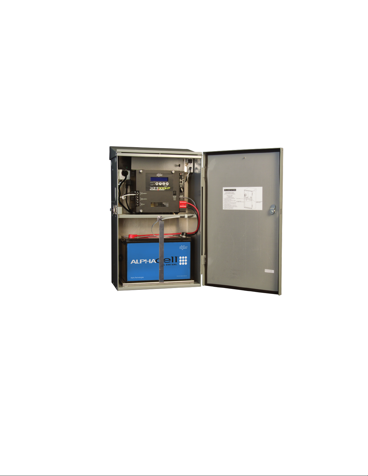
1.1 LPE Enclosures
The LPE Enclosures may be equipped with an optional AC service entrance, AC distribution
and are supported with a wide range of accessories, including the AlphaCellTM GXL batteries
and HPL-FT front terminal batteries providing extended standby runtime and life.
The LPE is specically designed for indoor or outdoor installations requiring lower power, a
smaller footprint and embedded DOCSIS® status monitoring capability. The LPE is available
in pole, wall or ground mount congurations. The LPE is an ideal solution for back-up power
where traditional equipment is too large and bulky.
031-302-B0-001 Rev A
Fig. 1-1, LPE Enclosure
9
Page 10

1.0 Introduction, continued
1.2 LPESpecicationsandOptions
Specications
Mechanical Option Part Number Description
Dimensions Batter y Harness: 875- 838 -20
746-152-20
H x W x D (in): 26 X 16.25 X 12 Batter y Heater Mat 746-130-20 Used in cold-climate applications
(mm) 660 X 413 X 305 Battery Retaining Bar (BRB) 605-948-A1 Secures batteries within enclosure
Weight (lb/ kg): 25 / 11.3 Coax Connection: 020- 019-3 5 SPI, 20A (1-2)
021-080-21 SPI RF, 20A (1)
12V Batter y Cable Kit (BCK)
12V Batter y Cable Kit - 2 Batteries
(BCK-2)
SPI, 20A (1-2)
Material: Exter ior powdercoated
aluminum
Battery: 220 GXL or two 70 HPL-FT Lightning Arrester 020- 098-24
Door and Lid Seal: Poron gasketing Service Entrance: 74 4- 656 -20 70A available
Color: Gray, white, and seafoam
green
Lid: Removable Surge Protection: 162-027-10
Door: Hinged, removable
Door Loc ks: 744-229-20 Provisions optional GEM
162-046 -10
745 -9 46-20
Status Indicators: 740-139-25 Local/Remote Indicator (LRI)
162-028-10
162-029 -10
LA- P+ 120V
LA -P-120 T
Surge Arrester Kit
75 Ω Coax, MF
75 Ω Coax, FF, w/Gnd
75 Ω Coax, FF
10
031-302-B0-001 Rev A
Page 11

2.0 Installation
CAUTION!
Never transport the unit with installed batteries. Doing so can cause injury to the installer or damage
the enclosure and equipment. Install the batteries after you transport the unit to the site and secure
it to the pad.
2.1 Enclosure Installation, Wall-mount
CAUTION!
The populated cabinet weighs approximately 150 lbs [68kg]. Installer needs to ensure the wall
is capable of supporting the loaded enclosure. Direct mounting to wall studs and 3/4" plywood
backing is required.
ATTENTION:
Before installing an enclosure, the location and method of mounting must be approved by the utility.
Recommended Tools and Materials:
• Ratchet with 1/2" and 9/16" socket (or metric equivalent)
• Level
• Two user supplied 3/8" x 4 1/2" (or larger) lag bolts (or metric equivalent)
• Two 3/8" stainless steel at washers, 1.00" max diameter x .08" min thickness
• Stud nder (optional)
• Drill with 1/4" drill bit or metric equivalent
• Tape measure
Tab
Installation Procedure:
1. Position the bracket on a wall capable of supporting 150 lbs
(68.0kg). Use a 3/4" plywood backing plate.
2. Maintain a minimum distance of 6" (153mm) from the bottom of the
bracket to the ground for proper enclosure ventilation.
3. Level the bracket vertically with the tab facing up. Center the
bracket on a wall stud.
4. Secure the bracket to the wall using two user-supplied 3/8" x 4 1/2"
(or larger) lag bolts and at washers specied above. The hardware
must sit ush inside the bracket dimples for proper installation.
Verify there is at least a 6" spacing between the bracket and the
ground.
5. Hang the enclosure on the bracket.
6. Securely fasten the enclosure to the bracket using the six 5/16"
bolts, lock washers and fender washers (supplied).
Fig. 2-1, Mounting Bracket
Lag Bolt
Lag Bolt
6" min from ground
031-302-B0-001 Rev A
11
Page 12

2.0 Installation, continued
2.2 Enclosure Installation, Steel or Concrete Pole
To mount the LPE on concrete or steel poles, two user-supplied mounting straps are required
(straps must be stainless, galvanized or equivalent). Most codes require the base of the
enclosure to be located a minimum height from the ground. Always verify height restrictions
before proceeding.
ATTENTION:
The majority of poles are the property of the local utility. Before installing an enclosure, the location and
method of mounting must be approved by the utility.
Required Tools and Materials:
• Two user-supplied pole straps to t pole (straps must be
stainless, galvanized, or equivalent)
• Ratchet with 1/2" socket
Installation Procedure:
1. Position the bracket so that the bottom of the bracket is
at least 6" off of the ground. Also make sure that the tab
is facing up. Secure it to the pole using the pole straps.
2. Hang the enclosure on the bracket.
Tab
12
3. Securely fasten the enclosure to the bracket using the six
5/16" bolts, lock washers and fender washers (supplied).
031-302-B0-001 Rev A
Page 13

2.0 Installation, continued
2.3
Enclosure Installation, Ground-mount
CAUTION!
Never transport the unit with installed batteries. Doing so can cause injury to the installer or damage
the enclosure and equipment. Install the batteries after you transport the unit to the site and secure
it to the pad.
ATTENTION:
It is the responsibility of the installer to meet the requirements of all applicable national and local codes. Alpha
Technologies assumes no responsibility or liability for failure of the installer to comply with the requirements of
all applicable local and national codes.
2.3.1 Pre-Installation
Before choosing a location and beginning installation, consider the following:
Provide adequate room for service personnel to remove the doors for battery •
installation and removal.
Wherever possible, select a site that is above the 100-year ood plain and away •
from residences.
Locate in the shade to minimize the effects of solar loading.•
Locate in an area with good airow.•
Locate at least 4" from the backside of the LPE to any wall.•
Locate away from sprinkler systems or other sources of forced water.•
Locate out of the prevailing wind to minimize the buildup of snow or accumulation •
of wind-borne dust.
Avoid locating the enclosure where it will be an obstruction or will inhibit visibility.•
Evaluate the soil conditions for suitability for the installation of the grounding •
system applicable to your particular installation.
Is utility power cabling run to and terminated at the site? •
NOTE:
The appropriate grounding method for a particular location depends on soil type, available space, local codes,
NEC (National Electric Code), and other site-specic characteristics.
031-302-B0-001 Rev A
13
Page 14

2.0 Installation, continued
PAD
POSTS
SPRINKLER HEAD
SIDEWALK
10’ (3m)
2.3 Enclosure Installation, Ground-mount
2.3.1 Pre-Installation, continued
Alpha Technologies, Inc. cannot anticipate all the ways a vehicle could threaten an
installed system or the specic type of protection that is appropriate for a particular
location. The following installation drawing for Alpha’s Standby Power systems are
general recommendations and not intended to be a specic guideline for protecting
the equipment. The numbers of bollard posts (or other protection devices) depend
upon equipment locations.
, continued
PAD
14
Fig. 2-2, Ground-mount Positioning and Safety
031-302-B0-001 Rev A
Page 15

2.0 Installation, continued
4
1
2
2' min.
2
2
2
2.3 Enclosure Installation, Ground-mount
, continued
2.3.2 Enclosure Grounding: Ground-mount
NOTE:
• Alpha generally recommends using the grounding method illustrated below. However, the grounding
method appropriate for a particular site depends on local codes, the NEC (National Electric Code), and
other site-specic characteristics.
• Alpha Technologies recommends 5 ohms maximum ground resistance between enclosure and ground
rods, in accordance with IEEE 1100-1999 Powering and Grounding Electronic Equipment.
• Alpha Technologies assumes no responsibility or liability for failure of the installer to comply with the
requirements of all applicable local and national codes. Where allowed, exothermic welding may be used
as an alternative to Burndy clamps and connectors.
CAUTION!
Corrosion-proof, twenty-ve-year connections suitable for direct burial must be used.
Burndy YGHP58C2W-2TN or Equivalent
Burndy YGHP58C2W-3 or Equivalent
Terminate at Service Entrance Ground Bar
8' (2.4m) Ground Rods
6’ (1.8m) Apart (min.)
031-302-B0-001 Rev A
Terminate at Enclosure Ground Bar
2' (0.6m)
min.
#2 AWG
3
Fig. 2-3, Suggested Grounding Method
Service Grounding (required)
#6 bare copper wire from service entrance ground bar, with two 1/2" X 8' (12.7mm x 2.4m) copper
1
ground rods, driven at least six feet (1.8 meters) apart.
Lightning Protection (optional)
2
Four 1/2" X 8' (12.7mm x 2.4m) copper ground rods, driven at least two feet from pad.
3
#6 bare copper wire loop, at least 30" (762mm) below grade, and terminated at each ground rod.
4
#6 bare copper wire from loop to enclosure ground bar in service entrance.
15
Page 16

2.0 Installation, continued
2.3 Enclosure Installation, Ground-mount
, continued
2.3.3 Ground-mount Installation
NOTE:
LPE enclosures require a pedestal mount kit for ground installation. Pedestal kit part number: 746-146-20
(gray); 746-146-21 (white); 746-146-22 (seafoam green)
Tools and Materials Required (customer supplied):
• Four 3/8-16” (10mm) anchor bolts (Hilti-style recommended)
• Four 3/8” (10mm) size stainless steel washers
• 2' x 2' (.6m x .6m) continuous vapor barrier (e.g. 30 lb. felt, neoprene pond liner,
or a heavy grade tar paper)
• Hammer drill
• 3/8” (10mm) drill bit
• 9/16” (14mm) wrench
• Metal punch
• Mallet or hammer
• Torque wrench
• Tape measure
• 3/8" socket
CAUTION!
A 25+ year continuous vapor barrier must be placed between the pedestal and the pad to prevent
moisture ingress and corrosion caused by metal-to-concrete contact.
Procedure:
1. Place the vapor barrier material on concrete pad.
2. Using the pedestal as a template, mark the vapor barrier material in the locations
of the four anchor bolts holes.
3. Drill 3/8" (10mm) holes through the vapor barrier and into the pad at the four
marked anchor points.
4. Position the pedestal over holes and insert anchor bolts. Torque the anchor bolts
to bolt manufacturer specications. If Hilti-style bolts are used, torque until head
pops.
5. On the enclosure, remove the three 3/4" (19mm) diameter knock-outs located on
the bottom of the enclosure shelf.
6. Lift the enclosure onto the pedestal. Align the three enclosure mounting holes
with the mounting holes on the top of the pedestal. Secure the enclosure to the
pedestal using the provided 1/4" (11mm) hardware. Torque to 75 in-lbs (8.5 Nm).
7. Trim away excess vapor barrier material.
16
8. The enclosure is now ready for the utility connection, power module, and
batteries.
031-302-B0-001 Rev A
Page 17

2.0 Installation, continued
2.3 Enclosure Installation, Ground-mount
2.3.3 Ground-mount Installation, continued
OUTSIDE OF PEDESTAL
INNER FLANGE
PAD
349.25
PEDESTAL ANCHOR HOLES
, continued
13.75
ENCLOSURE MOUNTING HOLES
PEDESTAL ANCHOR HOLES
203.20
8.00
Fig. 2-4, LPE Enclosure Pedestal
1115.14mm
43.90in
457.20mm
18.00in
509.93mm
20.08in
286.08mm
11.26in
031-302-B0-001 Rev A
Fig. 2-5, Enclosure-to-Pedestal Mounting
17
Page 18

2.0 Installation, continued
2.4 Dimensions
1
[304.80]
12.00
4
[111.13]
4.38
3
2
[391.41]
15.41
[657.94]
25.90
[153]
6 (to ground)
1
Optional SPI or SPI RF
2
Pole/wall mount bracket
3
Enclosure ground point
4
Removable lid
[250.57]
9.87
6
5
7
Knockouts for optional ACI, LRI indicator Lamps
6
Lockable door latch
7
Optional GEM lock
8
Hinged, removable door
9
8
9
18
5
Optional service entrance
031-302-B0-001 Rev A
Page 19

2.0 Installation, continued
2.5 Connecting the Utility Power
WARNING!
ONLY qualied personnel should connect the utility power. Power must be connected in
compliance with local electrical codes, and common safety practices must be observed.
ATTENTION
• Connection to utility power must be approved by the local utility before installing the power supply.
• Electrical codes require that a service disconnect switch be connected between the utility power source and
the Alpha power supply.
• Connection to the power supply must include an appropriate service entrance weather head.
Utility power enters the enclosure through an .875" knockout on the side or rear of the LPE. The
enclosure accepts a standard electrical tting.
A “high-magnetic” trip circuit breaker must be used in order to accommodate the high-inrush currents
associated with the start-up of transformers (400A, no-trip, rst-half cycle). Do not replace this circuit
breaker with a conventional service entrance circuit breaker. Alpha Technologies offers a high-
magnetic Square D circuit breaker and a BBX option (a UL Listed service entrance). Contact your
local sales representative for more information.
Description Alpha Part Number Square D Part Number
120V Installation — High-Magnetic (20A) 470-017-10 QO120HM
120V Installation — High-Magnetic (15A) 470-013-10 QO115HM
US BBX — External Service Disconnect 744-656-20 QO2-4L70RB
CAN BBX — External Service Disconnect 744-656-21 QO2-L70RB
031-302-B0-001 Rev A
19
Page 20

2.0 Installation, continued
2.5 Connecting the Utility Power, continued
2.5.1 Service Power
ATTENTION
Connecting to utility power must be performed by qualied service personnel in compliance with local
electrical codes and common safety practices. Connection to utility power must be approved by the local
utility before installing the power supply.
Electrical codes require that a listed service disconnect switch be installed between the power source and the
power supply. Connection to the power supply must include an appropriate service entrance weather head.
NOTE:
Utility power enters the enclosure through a 70A rainproof SUSE-rated breaker box.
The service entrance is wired as shown in the diagram below.
L1 (Black)
Copper Ground Wire
#8AWG minimum
Breaker
Grounding Point
(made to enclosure wall)
Fig. 2-6, 120Vac Service Entrance Wiring
From Utility
Neutral (White)
Neutral Bus
to Enclosure receptacle
20
031-302-B0-001 Rev A
Page 21

2.0 Installation, continued
2.5 Connecting the Utility Power, continued
2.5.1 Service Power, continued
The breaker option is wired as shown in the diagram below.
Neutral (White)
L1 (Black)
Ground (Green)
Fig. 2-7, 520-R Receptacle Wiring
031-302-B0-001 Rev A
21
Page 22

2.0 Installation, continued
2
3
1
2.5 Connecting the Utility Power, continued
2.5.2 Connecting Coaxial Cable
WARNING!
To prevent injury, DO NOT remove SPI cover until all sources of power have been
removed.
1. Verify SPI IS NOT connected to power supply.
2. Remove the two screws holding cover onto SPI chassis.
3. Remove SPI cover, exposing circuit board and seizure screw assembly.
Seizure Screw
Assembly
4. Insert Coaxial Termination into Output Port on bottom of SPI.
Circuit Board
Seizure Screw
Assembly
Stinger
Side View
of
SPI Case
Output Port
22
Coaxial Termination
031-302-B0-001 Rev A
Page 23

2.0 Installation, continued
ALT ON
2.5 Connecting the Utility Power, continued
2.5.2 Connecting Coaxial Cable, continued
5. Insert coaxial termination fully inside Seizure Screw assembly and tighten
Seizure Screws to 35 Inch-Pounds to prevent arcing and failure of unit.
6. Replace SPI cover and reinstall the screws.
7. Verify switch on top of SPI is in the ON position.
7
6
6
6
031-302-B0-001 Rev A
Fig. 2-18, Cover Replaced,
SPI Switched On
23
Page 24

2.0 Installation, continued
2.5 Connecting the Utility Power, continued
2.5.2 Connecting Coaxial Cable, continued
SPI OR SPI RF SIDE MOUNTING LOCATION
SPI OR SPI RF PRIMARY MOUNTING LOCATION
SECONDARY SPI MOUNTING LOCATION
24
Fig. 2-8, SPI and SPI-RF Mounting Locations
031-302-B0-001 Rev A
Page 25

2.0 Installation, continued
Battery Date Code located in this box
(1210 = DEC. 2010)
1 2 1 0
2.6 Battery Installation
WARNING!
Battery systems represent a risk of electrical shock and high short circuit currents.
The following precautions must be observed when maintaining batteries:
• Remove all personal metal objects (watches, rings, etc.).
• Use insulated tools.
• Wear eye protection and rubber gloves.
• Observe circuit polarities.
• Do not make or break live circuits.
• Do not lay metal tools and hardware on top of the batteries.
The batteries are enclosed in cabinets with limited access. Again, extreme caution must be exercised
when maintaining and collecting data on the battery system.
BatteryIdentication
Each battery contains a DATE CODE usually located on a sticker between the battery posts. This
date code must be recorded in the battery’s maintenance log. If batteries other than those installed by
Alpha are used, consult the battery’s documentation for date code type and placement.
031-302-B0-001 Rev A
Fig. 2-9, Battery Identication Label
25
Page 26

2.0 Installation, continued
2.6 Battery Installation, continued
WARNING!
To prevent arcing, never allow live battery cables to make contact with the enclosure.
Disconnect battery leads, or wrap the cable lugs with electrical tape.
CAUTION!
Threaded insert terminals require the use of 3/4" bolts. The use of 1" bolts will seriously damage the
battery. The only exception is the terminal with the large spacer for the in-line fuse link.
NOTE:
In battery congurations made up of multiple battery strings, Alpha strongly recommends the use of in-line
fuses.
Procedure:
1. Place the batteries on the enclosure’s battery shelf. Position the batteries to allow
maximum ventilation space between the batteries.
2. To make identication and record keeping easier, number and label the batteries. Record
each battery’s number and date code in the power supply maintenance log.
3. Using the battery arrangement diagram as a reference, achieve 12Vdc. Torque terminal
connections according to battery recommendations (see battery label for AlphaCell
batteries).
4. Check the polarity and voltage of the battery cable connector with a voltmeter to verify
correct connections. Do Not connect the battery string or strings to the power supply at this
time.
5. The power supply battery charger collects battery temperature compensation information
with a Remote Temperature Sensor (RTS) attached to one of the batteries. Refer to the
diagrams to determine which battery to attach the RTS to. Co-term the RTS onto the
negative battery terminal. Route the RTS connector onto the power supply shelf and
attach to provided cable clip. Do Not connect the RTS to the power supply at this time.
CAUTION!
Recheck the polarity and voltage of the battery cable connector before proceeding.
6. Route the battery cable connector into the power supply compartment. Do Not connect to
the batteries to the power supply at this time.
26
031-302-B0-001 Rev A
Page 27

2.0 Installation, continued
2.6 Battery Installation, continued
2.6.1 Battery Terminal Connections
NOTE:
Various types of batteries with different mounting styles and hardware may be shipped with the system.
ALWAYS refer to the battery manufacturer’s specifi cations for correct mounting hardware and torque
requirements. Use only the hardware and torque recommended by the battery manufacturer.
CAUTION!
Threaded insert terminals require the use of 3/4" bolts. The use of 1" bolts will seriously damage the
battery. The only exception is the terminal with the large spacer for the in-line fuse link.
3/4" x 1/4-20 Bolt
Split Washer
Flat Washer
Nut
Split Washer
Flat Washer
Battery Cable
In-Line Fuse Link
Flat Washer
1" or 3/4" x 1/4-20 Bolt
Battery Cable
Battery Terminal
Fig. 2-10, Hardware stack-up, Threaded Battery Insert
1" x 1/4-20 Bolt
Split Washer
Flat Washer
Fuse
Spacer
Battery Terminal
031-302-B0-001 Rev A
Fig. 2-11, Hardware stack-up, Threaded Battery Insert with optional in-line fuse
27
Page 28

2.0 Installation, continued
2.7 Power Supply Installation
For XM2-300 HP initial setup, please refer to the XM2-300 HP Quick Start Guide (p/n
017-877-B0-001), or the XM2-300 HP Technical Manual (p/n 017-877-B1-001).
For ELPM 300-48D initial setup, please refer to the ELPM 300-48D Installation
Manual (p/n 010-322-C0-003).
28
031-302-B0-001 Rev A
Page 29

3.0 LPE Enclosure Maintenance
Preventive Maintenance must be performed every three to six months. By establishing a routine
maintenance program and following the guidelines contained in this manual, the LPE Enclosure will
continue to provide years of trouble free operation.
Inspect the LPE Enclosure
Perform a complete inspection of the LPE Enclosure. Look for signs of rust and corrosion, paying
particular attention to the battery tray. Clean any rust or corrosion immediately.
Inspect the Mounting Brackets and Hardware
Carefully inspect the LPE Enclosure’s Mounting Bracket and mounting hardware. Look for signs of
unusual wear and loose hardware. Correct all mounting hardware failures immediately.
Check Battery Terminals and Connecting Wires
Care of the batteries is a critical step in any maintenance program. In addition to voltage checks,
visually inspect the batteries for signs of cracking, leaking, or swelling. To aid in quick identication
and tracking of voltages in the maintenance log, number the batteries inside the enclosure using
labels or masking tape, etc. Batteries are temperature sensitive and susceptible to overcharging
and under-charging. Since batteries behave differently in the winter than in the summer, Alpha’s
battery chargers automatically compensate for changes in temperature by adjusting oat and accept
charge voltages. See the power supply Operator’s and Technical Manual for complete Power Supply
Preventive Maintenance instructions.
Check each battery terminal and connection. Verify the posts are clean and the crimped connectors
are tight. Terminal connectors must be torqued to manufacturer specications at installation. If there
is an “in-line” or battery-mounted fuse in the battery cable, check the fuse holder and fuse. Verify the
terminals are properly greased with an approved battery terminal corrosion inhibitor such as NCP-2.
Record date of maintenance in the maintenance log.
Check Battery Open Circuit Voltage
Switch the power supply’s BATTERY BREAKER to the OFF position. Disconnect the battery
connector from the Inverter Module and measure the individual voltage across each battery. The
difference between any battery in the string must not be greater than 0.3 Vdc. Defective or marginal
batteries must be replaced with an identical type of battery. Record the unloaded battery voltages in
the maintenance log.
NOTE:
Whenever the power supply’s BATTERY BREAKER is turned OFF or the batteries are not connected, the
power supply will not operate in Inverter Mode in the event of a utility power failure.
031-302-B0-001 Rev A
29
Page 30

Page 31

Alpha Technologies Inc.
3767 Alpha Way
Bellingham, WA 98226
United States
Tel: +1 360 647 2360
Fax: +1 360 671 4936
Alpha Technologies Ltd.
7700 Riverfront Gate
Burnaby, BC V5J 5M4
Canada
Tel: +1 604 436 5900
Fax: +1 604 436 1233
Toll Free: +1 800 667 8743
Alpha Industrial Power Inc.
1075 Satellite Blvd NW,
Suite 400
Suwanee, GA 30024
United States
Tel: +1 678 475 3995
Fax: +1 678 584 9259
Alpha Energy
1628 W Williams Drive
Phoenix, AZ 85027
United States
Tel: +1 602 997 1007
Fax: +1 623 249 7833
Alpha Technologies Europe Ltd.
Twyford House Thorley
Bishop’s Stortford
Hertfordshire, CM22 7PA
United Kingdom
Tel: +44 1279 501110
Fax: +44 1279 659870
Alpha Technologies
Unit 504, 5/F,
Fourseas Building
No 208-212 Nathan Road
Kowloon, Hong Kong
Tel: +852 2736 8663
Fax: +852 2199 7988
Alpha Technologies GmbH
Hansastrasse 8
D-91126
Schwabach, Germany
Tel: +49 9122 79889 0
Fax: +49 9122 79889 21
Alphatec Ltd.
339 St. Andrews St.
Suite 101 Andrea Chambers
P.O. Box 56468
3307 Limassol, Cyprus
Tel: +357 25 375 675
Fax: +357 25 359 595
Alpha Innovations Brasil
Avenida Ibirapuera,
2120 – Cj 76
Moema - 04028-001
Santos SP, Brazil
Tel: +55 11 2476 0150
Fax: +55 11 2476 0150
Technologies Argus
First de Mexico
Anatole France Num. 17
Colonia Polanco
11560, México D.F.
Tel: +52 55 5280 6990
Alpha TEK ooo
Khokhlovskiy Pereulok 16
Stroenie 1, Ofce 403
Moscow, 109028
Russia
Tel: +7 495 916 1854
Fax: +7 495 916 1349
Alphatec Baltic
S. Konarskio Street 49-201
Vilnius, LT-03123
Lithuania
Tel: +370 5 210 5291
Fax: +370 5 210 5292
Visit us at www.alpha.com
Due to continuing product development, Alpha Technologies reserves the right to change specications without notice.
Copyright © 2010 Alpha Technologies. All Rights Reserved. Alpha® is a registered trademark of Alpha Technologies. 031-302-B0-001 Rev. A (05/2010)
 Loading...