

Page 1
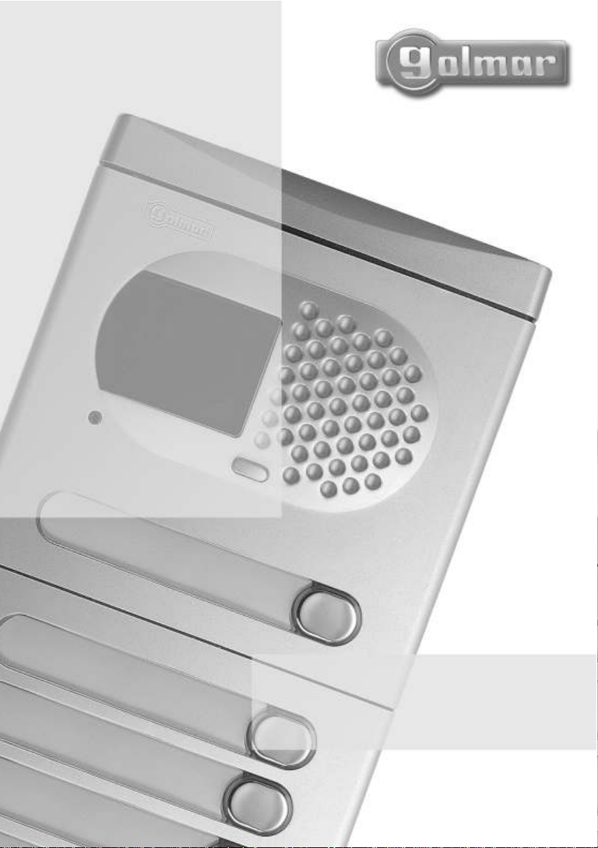
V
ideo door
entry system
with unpolarised
2 wire installation
V2PLUS
Instructions manual
TV2PLUS ML rev.0210
Page 2

INTRODUCTION
73
First of all we would like to thank and congratulate you for the purchase of this product manufactured by
Golmar .
The commitment to reach the satisfaction of our customers is stated through the ISO-9001 certification
and for the manufacturing of products like this one.
Its advanced technology and exacting quality control will do that customers and users enjoy with the
legion of features this system offers T o obtain the maximum profit of these features and a properly wired
installation, we kindly recommend you to expend a few minutes of your time to read this manual.
.
INDEX
Introduction...........................................73
Index.....................................................73
Starting recommendations
System characteristics
System operation
Door panel installation................................
Description..........................................75
Embedding box positioning
Embedding box installation
Electronic modules assembly
Door panel fixing
Placing the nameplate labels
Push buttons wiring
Push buttons coding
EL500/V2 Plus configuration
Autodiagnostic LEDs
Lamps wiring
Final adjustments
Closing the door panel
Power supply installation
Lock release installation
Platea V2Plus monitor
Description..........................................86
Function push buttons
End of line / amplifying video signal ........87
................................... 74
....................................... 84
....................... 73
............................. 74
................... 76
....................77
................. 78
................................. 79
..................80
..........................80-81
..............................82
................. 83
.............................83
................................. 84
......................... 85
......................... 85
.......................... 85
..................................
...........................87
Identification label................................87
Monitor connection block description
Monitor installation
Programming
T-7822VD .................................
Description..........................................91
Function push button
Connection terminals, JP3 configuration
T elephone installation
Programming
Optional connections
External lock release activation
Call from the apartment door
Additional monitor , telephone or
call repeater
Auxiliary devices activation
Installation diagrams
Without a distributor
With a 1 line distributor
With a 4 line distributor
With a.c lock release...................105-106
T roubleshooting hints
Notes...........................................108-110
Compliance.........................................
T elephone
...............................89
.......................................90
.............................91
...........................92
.......................................93
..................................
........................................95
.................... 96
...................................
........................97-98
...................99-100
.................101-104
..........................107
......88
...............94
.................94
.91
111
STARTING RECOMMENDATIONS
O Do not use excessive force when tightening the power supply connection block screws.
O Install the equipment without the power connected
O Before connecting the system, check the connections between door panel, monitors, telephones and
the transformer connection Do always follow the enclosed information
O When starting the equipment for the first time, or after a modification, the system will remain inactive
for a some seconds while it initiates
O Use Golmar RAP-2150 cable
. .
.
.
.
Page 3

74
SYSTEM CHARACTERISTICS
O Video door entry system with simplified installation (2 wire bus without polarity
O 1 access door panel, (up to 3 access door panel with MC -V2Plus multiplexer)
O Up to 32 monitors or telephones per installation without using converters or multiplexers
O Up to 32 apartments with push button door panels and 32 apartments with coded panel
(being necessary the use of digital converter CD-V2Plus).
Up to 120 apartments and 120 monitors or telephones per installation or backbone (being
O
necessary the use of multiplexer MC-V2Plus).
O
Up to 16 monitors or telephones and apartments in daisy chain installations (without distributor)
per installation or backbone without using converters or multiplexers.
O Up to 3 elements (monitors, telephones or call repeaters) per apartment
O Acoustic call acknowledgement signals
O Maximum distance between the door panel and the last monitor (telephone)
O Maximum distance between the distributor and monitor (telephone)
O Maximum length of all the bus wiring in the installation
O Door opening timed at 3 seconds
O a.c or d.c lock release operated by relay
O With Platea-V2Plus monitor
wPrivacy on audio and video communications
“” .
w Video-spy function with the communication channel remaining free
“” .
w Autoswitch-on function
wContact free auxiliary push button for activating auxiliary devices
eVoltage free contact (Max. current: 40mA
B/W & Color Monitor.
w
w : .
Three-position control for call volume maximum, medium and minimum
wBrightness and contrast control
wDifferent call tones which identify the call procedure (door panel or apartment door
wInput for external door bell push button
With T7822VD :
O telephone
Total .
w private conversation
w :
Contact free auxiliary push button for activating auxiliary devices
e ).
Voltage free contact (Max. current: 40mA
w : .
Three-position control for call volume maximum, medium and off
w ).
Different call tones which identify the call procedure (door panel or apartment door
wInput for external door bell push button.
:
.
: 15m.
: 400m.
.
.
.
:
).
(color control in case of color screen).
.
).
.
.
.
: 100m.
).
SYSTEM OPERATION
To make a call the visitor should press the push button corresponding to the apartment he / she
O
wants to contact acoustic tones will be heard confirming the call is in progress once the push
button has been pressed At this moment the call will be received at the monitor (telephone) in the
dwelling During the call the visitor can correct his / her call by pressing the push button
corresponding to the desired apartment, cancelling the original call
The call tone lasts for 45 seconds. Unknown to the visitor, his/her image is displayed on the master
O
monitor just a few seconds after the call is received To see the image on a slave monitor press the
push button. This will cause the image on the other monitor to disappear If the call is not
answered in 45 seconds, the system will be freed
To establish communication pick up the monitor (telephone) handset
O .
The communication will last for 90 seconds or until the handset is replaced Once the communication
O .
has finished the system will be freed
To open the door, press the door release push button during call or communication progresses with
O :
one press, the lock release is activated for 3 seconds pressing once the push button
The description of the function push buttons is shown on pages
O .
: Some
.
.
.
.
.
.
.
.
87 and 91
Page 4
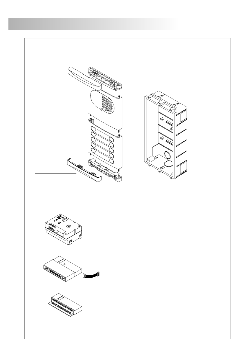
DOOR PANEL DESCRIPTION
75
Closing heads
600
Grille module
Push buttons module
1xxx
2xxx
3xxx
Sound module
, .
on video systems with b/w camera
EL530
, on video systems with color camera.
EL531
, on audio systems.
EL540
oor panel description
D
CE embedding boxes-6xx
.
Microprocessor circuit
EL500/V2PLUS
Push buttons encoder
EL516
, .on systems with more than eight push buttons
, .on audio and video systems
Page 5
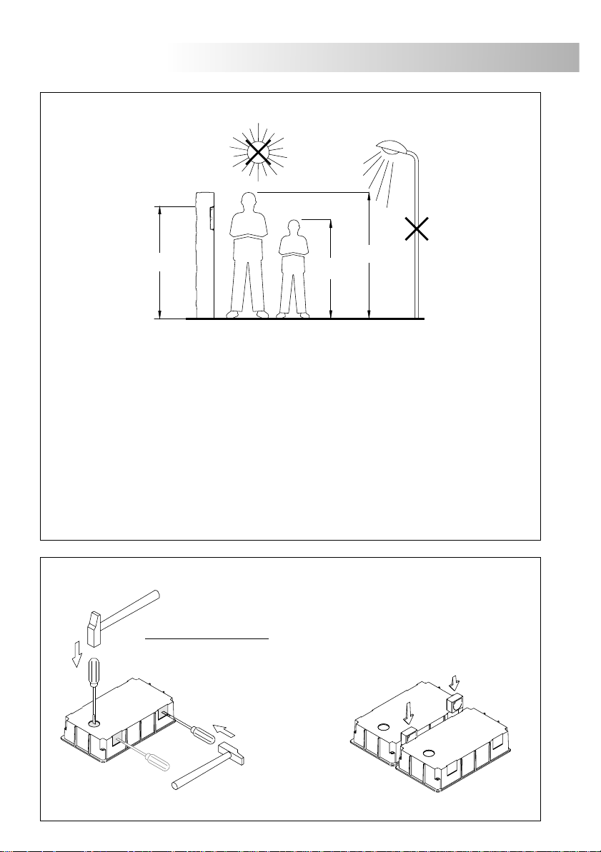
76
DOOR PANEL INSTALLATION
mbedding box positioning
.
E
1650
The upper part of the door panel should be placed at 1,65m. height roughly The hole dimensions
.
will depend on the number of door panel modules
Modules
Model
W
H
D
The door panel has been designed to be placed under most of the environmental conditions
However, so as to extend its service life, it is recommended to take additional precautions
...).
(visors, covered areas To obtain a quality image on video door entry systems,
...).
avoid direct incidence from light sources (sun, street lights,
1
CE610
125
140
56
Compact
CE615
125
220
56
1450
1850
2
CE620
125
257
56
.
3
CE630
125 mm.
374 mm.
56 mm.
.
P
Break the botton flange to pass the cables through it
panels
attach the embedding boxes using UC junctions
with more than one embedding box, break the side flanges and
.
reparing the cables entry
. In case of door
.
Page 6
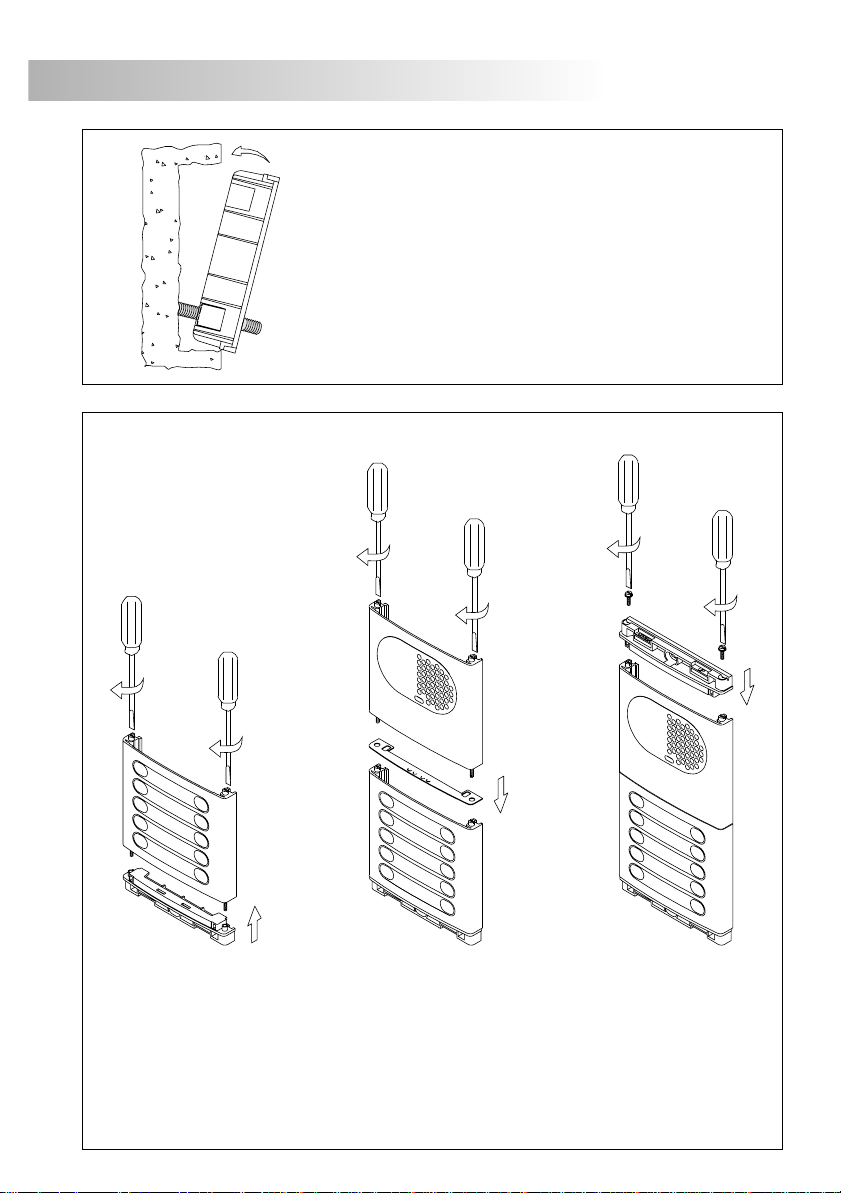
DOOR PANEL INSTALLATION
77
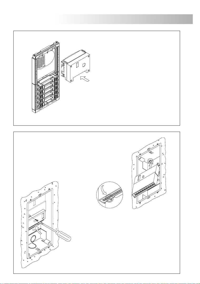
ssembly the door panel modules
A
lace the embedding box
P
Pass the wiring through the hole made in the bottom
.
part of the embedding box Level and flush the
.
embedding box Once the embedding box is
placed, remove the protective labels from the
.
attaching door panel holes
.
.
Insert the header DOWN marked in the lower module and fix it by screwing the
.
module shafts
Place the module spacer between lower and next modules, assuring that the spacer
. .
adjustment notches are inside the panel Fix the module by screwing the shafts
R
epeat this procedure in case of door panels with one more
).
module (the maximum number of modules placed vertically is three
Insert the header UP marked in the last module and fix it by screwing the supplied
.
screws
Page 7
78
DOOR PANEL INSTALLATION
ssembling the EL500/V2PLUS microprocessor circuit
A
and the EL516 push buttons encoders
The EL500/V2PLUS circuit is to be assembled on the
.
top of the embedding box Insert the circuit in the
.
top flanges of the embedding box (1) Push-in the
circuit in the bottom flanges (2) by pressing the
.
pcb board
.
ssembly the sound module
.
A
I.
nsert the sound module in the grille module
For a proper assembly, align the light
push button and the microphone rubber
of the sound module with its corresponding
holes in the grille module
.
1
2
2
1
To assemble the EL516 encoder, screw the top tab of
the case to the corresponding plastic lug of the
.
embedding box
Place the circuit on the inferior flanges and screw
.
it into the embedding box
In case of more than one encoder, place them
.
underneath or in the next embedding box
The use of EL516 encoders is only necessary for
.
panels with more than 8 push buttons
Each encoder allows the connection of 15
.
push buttons
Page 8
DOOR PANEL INSTALLATION
79
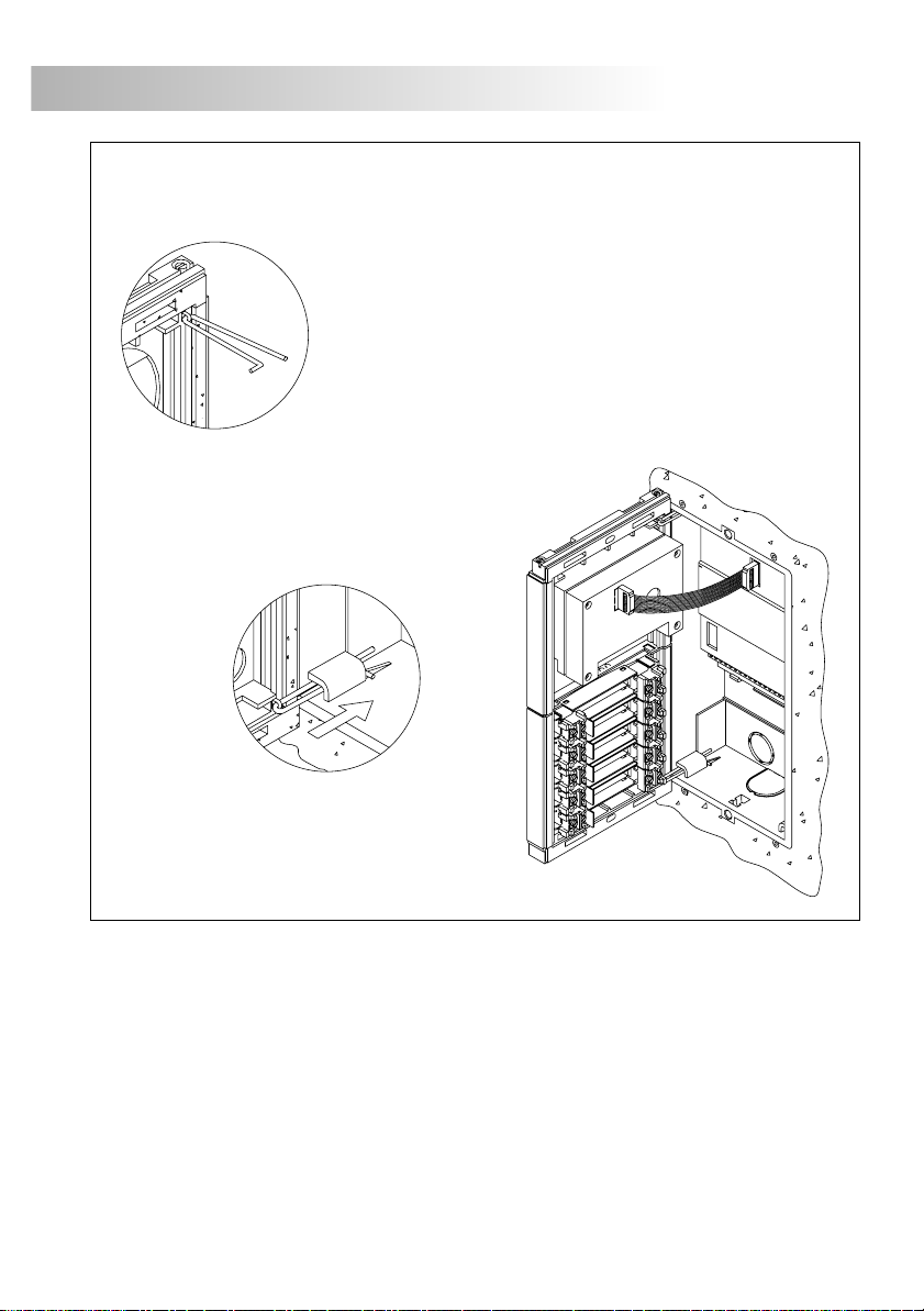
old the door panel on the embedding box
H
Select a direction to open the door panel; this selection should
e .
eas the door panel wiring
The opening direction will be settled through the hinges position,
.
that must be passed through the header clips as shown For
example, if the hinges are placed on both clips of the lower
header, the door panel will open downwards; if they are placed
on the right clips of both headers, the door panel will open
.
to left
To hold the door panel on the embedding
box, insert the hinges in the embedding
box lockers as shown
.
.
Link the sound module with the EL500/V2PLUS
microprocessor circuit by using the supplied
flat cable
.
Page 9
80
DOOR PANEL INSTALLATION
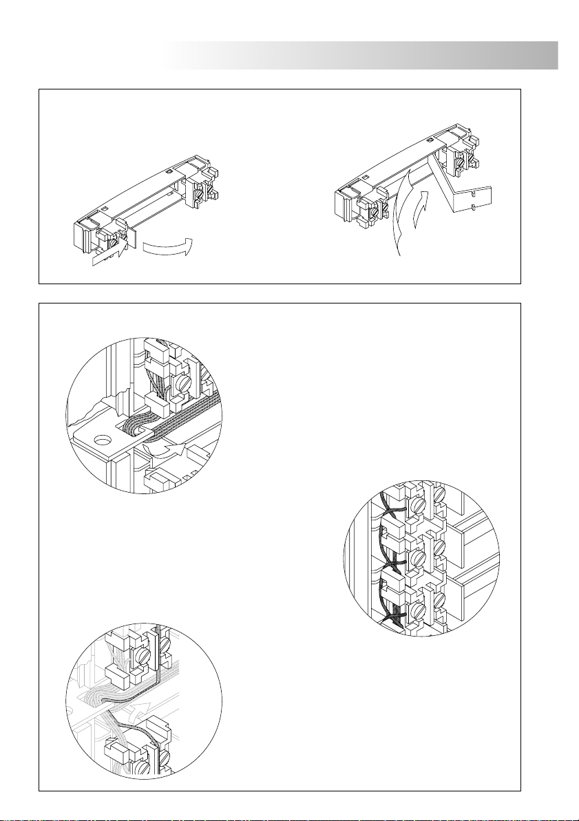
lace the nameplate labels
P
.
Open the label holder.
For a quality finish, pass the push buttons wires through
.
the spacer hole of the closest module It's
recommended to use wires with sections
between 0,1 and .
P
2
0.25mm section
Place the label
and close .
ush buttons wiring
.
wist the call wires as shown The call wires will be
T.
connected to the EL500/V2PLUS microprocessor
circuit
.
or to the corresponding EL516 push buttons
encoder
IMPORTANT:
terminal of the several push buttons modules
.
The common terminal of the push buttons
contained in a module are linked from factory
.
This wire must be connected to the CP terminal
of the EL500/V2PLUS microprocessor module
and to the corresponding CP terminal of its
EL516 encoder circuit
(if there is).
link the push buttons common
Page 10
DOOR PANEL INSTALLATION
81
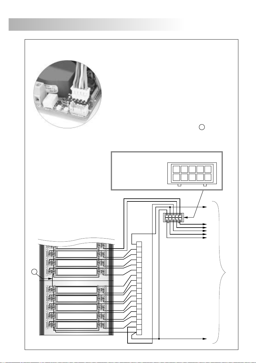
ush buttons wiring
P
A
.
Plug the push buttons connection cable to the CN6
connector of the EL500/V2PLUS microprocessor module;
this cable has 10 conductors (P1 to P8, B and CP) for the
connection of push buttons or EL516 encoders
.
The CP terminal must be connected to the push buttons
common terminal and to the CP terminal of the push
buttons encoder circuits onnect B terminal to the B
terminal of the encoders
. C
.
Link the different push buttons common terminals of all the
push buttons modules as shown in diagram
A .
Link the push button inputs (P1…P8) to the push buttons
and/or to the encoder circuits (P) as shown in the example
CP
P8
Top view
B
P1P6P2
P7
P5
P3
P4
P4
P5
P6
P7
P8
CP
Colours codes
CP: Black
B: Red
P1: Green
P2: Orange
P3: Blue
P4: Violet
P5: Yellow
P6: White
P7: Brown
P8: Grey
B
1
2
3
EL-516 module terminals
4
5
6
7
8
9
10
11
12
13
14
15
P
CP
.
B
To other encoders or push buttons
Page 11
82
DOOR PANEL INSTALLATION
ush buttons limit
P
The number of push buttons that can be wired is limited to a maximum of 32 apartments, which
can be increased up to a maximum of 120 apartments (requires the use of the riser multiplexer
MC-V2Plus) and will be distributed in the EL516 encoders as shown in the table below:
.
:
Without EL516 circuits
:
With 1 EL516 circuit
:
With 2 EL516 circuits
With 3 EL516 circuits:
With 4 EL516 circuits:
With 5 EL516 circuits:
With 6 EL516 circuits:
With 7 EL516 circuits:
With 8 EL516 circuits:
REMEMBER: The maximum number of apartments is 32, but this can be increased to 120
(requires the use of the multiplexer MC-V2Plus).
8
7 + 15 = 22
6 + 15 + 15 = 36 (max. 32 without using multiplexer).
5 + 15 + 15 + 15 = 50
4 + 15 + 15 + 15 + 15 = 64
3 + 15 + 15 + 15 + 15 + 15 = 78
2 + 15 + 15 + 15 + 15 + 15 + 15 = 92
1 + 15 + 15 + 15 + 15 + 15 + 15 + 15 = 106
0 + 15 + 15 + 15 + 15 + 15 + 15 + 15 + 15 = 120
ush buttons digital code
P
13
13
28
43
58
73
88
103
118
14
14
29
44
59
74
89
104
119
15
15
30
45
60
75
90
105
120
The codes shown in the shaded column correspond with the push buttons directly connected to
the corresponding CN6 terminal of the EL500/V2PLUS circuit, or to the terminal 1 of its
corresponding EL516 encoder
1
1
P1
P2
16
31
P3
P4
46
61
P5
P6
76
91
P7
EL500/V2PLUS circuit terminals
P8
106
2
2
17
32
47
62
77
92
107
3
3
18
33
48
63
78
93
108
.
EL516 circuit terminals
4
5
6
4
5
6
19
20
21
34
35
36
49
50
51
64
65
66
79
80
81
94
95
96
109
110
111
7
7
22
37
52
67
82
97
112
8
8
23
38
53
68
83
98
113
9
9
24
39
54
69
84
99
114
10
10
25
40
55
70
85
100
115
11
11
26
41
56
71
86
101
116
12
12
27
42
57
72
87
102
117
.
.
REMEMBER:
maximum number of push buttons (apartments) is 32 if the installation uses distributors, or
16 if it does not (daisy chain
Up to 8 EL516 encoders (requires the use of the multiplexer MC-V2Plus), can be used to
increase the number of push buttons (apartments) to 120 if the installation uses distributors
and 64 if it does not (daisy chain).
The number of EL516 encoders which can be used is limited to 2, given that the
).
Page 12

DOOR PANEL INSTALLATION
6
6
escription of the configuration dip-switch of the
EL500/V2PLUS microprocessor module
D
The SW1 configuration dip switch is located at the right side of
the circuit. It is accessed by opening the terminal connection
block protection cover
.
Set the master door panel to OFF, if there is a MC-V2Plus multiplexer
with access doors panels in the installation or backbone, only one door
panel can be configured as the master, the rest must be slaves and set to
ON. Each backbone must only have one door panel or CD-V2Plus
converter configured as the master.
Set to ON the switch number 2 for monitor or telephones programming
Once the programming has finished, return the switch to the OFF position.
The programming process is described on pages 90 (monitors) and 93
(telephones)
Placed in ON allows autoswitch-on (audio and video communication without
having been called), if there is a MC-V2Plus multiplexer with access doors
panels in the installation or backbone activate this function only in one of
them; in systems with general door panel (necessary the use of converter CD-
V2Plus) this function can be activated in one door panel of each backbone.
Selects whether the door panel has a telecamera or not If the
door panel does not have a telecamera.
.
.
83
.
. Set to ON
Factory default
Green
If the short circuit is removed before 2
*
minutes (approx.), the door panel will
automatically reset. Past this time it
will be necessary to switch it off and
then switch it on again the power.
Red
Set to ON so that the volume tone emitted by the door panel are HIGH,
or set to OFF if a LOW volume tone is desired.
Set to ON if there are distributors in the backbone (single-user or multi-
user) or the door panel is connected to the multiplexer MC-V2Plus at a
distance of to OFF if the backbone is daisy chain (without
distributors
at a distance < 50m.
> 50m, set
) or the door panel is connected to the multiplexer MC-V2Plus
_
escription of autodiagnostic LEDs
D
T
he autodiagnostic LEDs are found on the right side of the
.
circuit, beside the CN6 connector
Green LED
Fixed: .Correct operation
Blinking:
).
Red LED
Fixed: More than one module is configured as the Master
Blinking: *
Door panel is being programmed (dip switch
2 is ON
or module is faulty.
There is a short circuit in the installation between
the bus wires.
.
Page 13

84
DOOR PANEL INSTALLATION
amps wiring
.
L
Once the nameplate labels are placed, wire the lamps
from different modules and connect them to terminals
.
L1 and L2 of the sound module
If the number of door panel lamps is higher than six, c
the TF-104 transformer between the ~1 and ~2 terminals
of the sound module and change the JP2 jumper position
NOTE: .
Don't change JP1 jumper position JP1 and JP2 jumpers are placed on the left side of the
sound module terminal connection block
If the TF-104 transformer with alternating current lock release is also used, wire ~1/~2
terminals of the sound module with CV1/CV2 terminals respectively of the EL-500/V2Plus.
inal adjustments
.
onnect
.
.
F
Sound Module:
If after starting the system it's considered that the audio
volume isn't correct, proceed with the necessary
.
adjustments as shown
The telecamera has a pan and tilt mechanism If the
.
orientation is not adequate then correct its position
In case of low light conditions, an external illumination
can be activated by connecting a SAR-12/24 relay
between the '+H' and 'L2' terminals of the sound module
.
.
IMPORTANT:
exceed 1,8A to 30Vdc/250 Vac
.
See document TSAR-12/24 for its connection and characteristics.
Microprocessor Circuit:
The EL500/V2PLUS microprocessor circuit has a
potentiometer “PT1” to remove the possible
.
audio feedback in the installation The potentiometer
can be accessed via a hole, making it unnecessary
.
to remove the circuit protection cover
.
Make the adjustment as shown in the picture
The power to the SAR-12/24 relay must not
.
IMPORTANT:
the potentiometer “PT1”, then consult the “troubleshooting
hints” section on page
If feedback persists after having adjusted
107.
Page 14

DOOR PANEL INSTALLATION
85
lose the door panel
.
C
ix the door panel by using the supplied
F
screws and washers
.
inish the door panel assembly by pressing
F
the closing heads
.
If it were necessary to open the door panel
once closed, use a plain screwdriver to
remove the closing heads
.
POWER SUPPLY INSTALLATION
etail of the FA-V2PLUS power supply installation
.
D
Install the power supply in a dry and protected place
f3,5 x 45
DIN-7971
f3,5 x 45
DIN-7971
The power supply can be installed on a DIN 46277
.
guide simply pressing it To disassemble the
power supply from the DIN guide, use a plain
.
screwdriver to lever the flange as shown on the picture
The FA-V2PLUS power supply uses .
.
Replace the protection cover once the input terminals have been wired
without risk of drip or water projections.
To avoid damage, the power supply must be firmly fixed.
The current regulation forces you to protect the power
supply with a thermo-magnetic circuit breaker.
To install the power supply directly on the wall, drill two
holes of Ø6mm. and insert the wallplugs Fix the
.
power supply .
6 units over DIN guide
with the specified screws
DIN 46277
.
LOCK RELEASE INSTALLATION
ock release installation
.
L
If the lock release will be installed in a metal door, use a Ø3,5mm.
drill and tap the hole
.
In case of wood door, use a Ø3mm. drill
.
IMPORTANT:
The lock release must be 12V d.c or a.c (see pages 97 to 106).
With a.c lock release, place the varistor provided on the lock release terminals.
f3,5 x 25
DIN-7972
M 4 x 8
DIN-963
Page 15

86
MONITOR DESCRIPTION
escription of the Platea V2Plus monitor
.
D
REF.
PLATEA V2PLUS
COD.
g
a
h
b
c
d
i
e
j
f
INTER A1
ATENCIÓN
Alta tensión. No abrir la tapa.
Manipular sólo por personal
del servicio técnico.
WARNING
High voltage. Don't open cover.
Handle only by technical service.
11784042
VERSIÓN: Nº SERIE:
00000000000
X.XX
CODIGO / CODESLAVE MASTER
ESCALERA
PISO
STAIR
FLOOR
PUERTA
DOOR
k
a.
Telephone handset
b.
B/W or color screen
c.
Front film
Inoperative push buttons.
d.
e.
Function push buttons
f .
Cord.
g.
A.
h.
Identification label
i .
Connecting points
j .
Sw2 Dip-switch.
k.
Three positions call reception volume control
l .
Cable slot.
m.
Contrast control colour control in colour monitors
n .
Brightness control
.
ttachment holes
.
(depending on the model).
.
.
.
().
.
n
m
l
.
Page 16

MONITOR DESCRIPTION
87
unction push buttons
.
F
Regardless of the handset's position, it activates the PA and PB voltage-free contacts
The JP2 jumper must be inserted (see page 96
), or activate the SAR-2Plus unit if the
JP1 jumper is inserted (see page 96), this second process taking place during call
reception or communication.
.
If the handset is on the craddle allows to see the picture from .
If the handset is picked up, audio and video communication can be established with
the door panel ( ).
if there is communication already in progress
.
uring call reception and communication processes, it allows lock release activation
D.
nd of line and amplifying the video signal
E
the autoswitch-on function must be activated This function is disabled
The Sw2 configuration dip switch is located
on the rear of the monitor .
No function.
No function.
Set to ON to configure with the end of line resistor in monitors
where bus wires terminate
.
Set to OFF only for intermediate monitors
.
No function.
.
the door panel
.
.
Set to On the monitors:
That distance is more than 80 m. from door panel or multiplexer.
Connected from output No.17 of the disributors or with multiplexer from
output No. 25 of the distributors.
In an installation without distributors (daisy chain) from monitor No.9.
Set to OFF the rest of monitors, and with a multiplexer the monitors con-
Factory default
nected in riser without distributors (daisy chain).
escription of the identification label
D
PLATEA V2PLUS
11784042
INTER A1
ATENCIÓN
Alta tensión. No abrir la tapa.
Manipular sólo por personal
del servicio técnico.
WARNING
High voltage. Don't open cover.
Handle only by technical service.
VERSIÓN: Nº SERIE:
X.XX
ESCALERA
STAIR
00000000000
CODIGO / CODESLAVE MASTER
PISO
FLOOR
PUERTA
DOOR
er
.
REF.
COD.
For an easiest repair, replacement or increasement
of the existing monitors, fill the identifying label
.
information
.
MASTER: m .
SLAVE: 2.
INTER:
A1:
CODE: 82).
STAIR: .
aster monitor
slave monitor 1 or slave monitor
no function
no function
.
.
push button code (see page
no function
Page 17

88
CONNECTION BLOCK DESCRIPTION
escription of the RCPL-V2Plus monitor connection block
D
a
b
50mm.
Colocar la parte superior de la regleta a 1,60m. del suelo.
Place the top part of the monitor connector at 1,60m. from the floor.
CODE:
11784084
b
a
a. (x4).
Wall attachment holes
b. (x2).
Monitor attachment hooks
c. .
Vertical wiring input
Attachment clip
d. .
Central wiring input
e. .
Installation terminals
f. :
- Bus In:
- Bus Out:
- HZ:
- PA, PB:
Digital communication bus input to monitor
Digital communication bus output to additional monitor/telephone
Door bell push button connection
Voltage free contacts
REF:
RCPL-V2PLUS
.
LOTE:
00000000
50mm.
Presionar para abrir.
Press to open.
.
.
c
d
e
BUS
IN
BUS
OUT
HZ
PA
PB
f
.
.
The Bus In and Bus Out terminals facilitate a daisy chain connection of other monitors or telephones
If the monitor is not placed on the connection block, subsequent daisy chain units will not be
.
powered
.
Page 18

MONITOR INSTALLATION
6
89
ix the monitor connection block to the wall
.
F
Avoid placing the monitor near sources of heat, in
.
dusty locations or smoky environments
To install the monitor directly over the wall, drill two
.
holes of Ø6mm. and use the supplied screws
The upper part of the monitor connection block must
.
be placed at 1,60m. height roughly The minimum
distance between the monitor connection block and
5cm.
the closest object must be
ix the monitorF.
Place the monitor at right angles to the
connection block and align the attaching
holes of the monitor with the attachment
hooks of the connection block, as it is
.
shown on the drawing
Lock out the monitor. Press the right side till the
.
attachment clip locks the monitor firmly
To disassemble the monitor from the connector,
use a plain screwdriver to release the
.
attachment clip Remove the monitor from
the connection block, taking special care
.
that it does not fall
Page 19

90
6
MONITORS PROGRAMMING
rogramming the monitors
.
P
Locate the configuration dip switch situated under the protection
cover of the EL500/V2PLUS microprocessor circuit and set
n 83.
umber 2 to ON as described on page
The door panel will reproduce a sound to advise that the system
has entered into programming mode
double
click
st
Master 1 Slave
.
With the door release push button pressed,
pick up the monitor's handset .
To show that the system is ready for programming,
the door panel and the monitor's handset will
reproduce tones and an image will appear on the
monitor. Audio and video communication can
.
also be established
T.
he door release push button can be released
ress the door panel push button that
P
.
.
To program the monitor as master, replace the handset
1
To program it as Slave press the lock release push
button once. After the door panel and handset reproduce a
short tone, replace the handset If a long tone is reproduced
.
then an error has occurred; reconfigure the monitor
To program it as 2 Slave press the lock release push button
twice. After the door panel and handset reproduce two short
tones, replace the handset If a long tone is reproduced then
.
an error has occurred; reconfigure the monitor
.
nd
st
will call to this monitor
At this moment both door panel and
handset will reproduce tones
.
.
nd
2 Slave
Each apartment must have one master unit only; if there is a parallel unit, be it a
monitor or telephone, it must be configured as slave.
Make a call to check that the monitor has been successfully programmed
.
Repeat these steps to program the rest of monitors
Once the programming has finished, set the programming switch to
If you don't, the door panel will reproduce a sound to advise that the
.
system is still into programming mode
.
OFF.
Page 20

TELEPHONE DESCRIPTION
91
escription of the T-7822VD telephone
D
b
d
a
c
e
f
h
i
g
e
a.
Telephone handset
b.
Speaker grille
c.
Microphone hole
d.
Subjection .
e.
Telephone cord connectors
f.
Door .
release push button
g.
Hook switch
h.
Auxiliary function push button
i.
Volume control
.
.
.
hole
.
.
unction push buttons
.
.
F
uring call reception and communication processes, it allows lock release
D
activation
.
.
.
Regardless of the position of the handset, activate the PA and PB voltagefree contacts with the JP1 jumper inserted (see page 96), or activate the
SAR-2plus unit if the JP2 jumper is inserted (see page 96), this second
process taking place during call reception or communication.
erminal connector description and JP3 configuration jumper
T
BUS
T-7822VD:
JP3 configuration jumper:
JP3
JP3
*Factory default
V2Plus system (video)
2Plus system (Audio)
HZ PAS-
BUS E.of.Line
HZ PBS+
S+, S-:
BUS:
HZ :
PA, PB:
BUS:
End of Line:
.
Connection to an S-45 call repeater
Digital communication bus
Door bell push button input
Voltage free contacts (see page
Digital communication bus
End of line resistor
.
.
96 .
.
.
.
)
Page 21

92
ix the telephone to the wallF.
TELEPHONE INSTALLATION
It is necessary to open the telephone for wiring and fixing
purposes To open the telephone, insert a plain
screwdriver into the slots and gently lever as shown in
the drawing. .
Avoid placing the telephone near sources of heat, in dusty
locations or smoky environments The telephone can be
fixed using an electrical embedding box or directly on the
wall, as shown on the picture If the telephone will be
installed directly over the wall, drill two holes of Ø6mm on
the specified positions, using 6mm wall plugs and Ø3.5 x
25mm screws
.
.
.
ass the installation wires through the corresponding hole and connect
P
them as shown on the installation diagrams lose the telephone as
shown on the picture Once the telephone is closed, connect the
handset using the telephone cord and put it on the cradle
.
. C
.
Page 22

TELEPHONES PROGRAMMING
93
rogramming the telephones
.
P
ocate the configuration dip switch situated under the protection
L
cover of the EL500/V2PLUS microprocessor circuit and set
number 2 to ON as described on page 83
The door panel will reproduce a sound to advise that the
system has entered into programming mode
With the door release push button pressed, pick up
To show that the system is ready for programming, the
.
The .
To program the telephone as master, replace the handset
To program it as Slave press the lock release push button
once. After the door panel and handset reproduce a short tone,
.
replace the handset If a long tone is reproduced then an error
.
has occurred; reconfigure the telephone
Master Slave 1
st
.
.
the telephone's handset .
door panel and handset will reproduce a tone, and audio
communication can be established
door release push button can be released
st
1
Press the door panel push button that
.
will call to this telephone
At this moment both door panel
and handset will reproduce tones
.
.
nd
To program it as Slave press the lock release push button
twice. After the door panel and handset reproduce two short
.
double
click
nd
2 Slave
Each apartment must have one master unit only; if there is a parallel unit, be it a monitor
or telephone, it must be configured as slave.
Make a call to check that the telephone has been successfully programmed
.
Repeat these steps to program the rest of telephones
Once the programming has finished, set the programming switch to
If you don't, the door panel will reproduce a sound to advise that the
.
system is still into programming mode
tones, replace the handset If a long tone is reproduced then
.
an error has occurred; reconfigure the telephone
2
.
OFF.
Page 23

94
OPTIONAL CONNECTIONS
xternal lock release activation
.
E
The lock release can be activated at any moment by using an external push button, that must be
connected between of the door panel
'CV1' and 'CV2' .
This function will allows to exit from the building being not necessary the use of a key
EL 500/V2PLUS
CV1CV2
oor bell push button connection.
.
D
Platea V2Plus T-7822VD
The monitors and the telephones, incorporate as standards the
call reception from the door bell push button. This feature spares the use of a bell, by placing a
push button between the "HZ" monitor or telephone terminals
The reproduced acoustic tones are different depending on their provenance, that allows the
user to distinguish where the call is made from If during a conversation a call is made from
the apartment door, acoustic tones will be reproduced on the handset to advise that someone
.
is calling
.
.
Platea V2Plus
BUS IN
BUS OUT
HZ
PA PB
BUS
T-7822VD
HZ PAS+ HZ PBS-
BUS E.of.line
Page 24

OPTIONAL CONNECTIONS
95
onnecting a monitor, telephone or additional call repeater
.
C
REMEMBER: The total number of elements per apartment (monitors, telephones or call
repeaters) must never exceed three units.
Additional monitor
Platea V2Plus
BUS IN
BUS OUT
Platea V2Plus
BUS IN
BUS OUT
HZ
HZ
PA PB
Additional telephone
Sw2
PA PB
Platea V2Plus
BUS IN
BUS OUT
BUS
HZ PAS+ HZ PBS-
HZ
T-7822VD
PA PB
BUS
Sw2Sw2
E.of line
S-45
S+ S-
Additional call repeater
BUS
T-7822VD
HZ PAS+ HZ PBS-
BUS
R.1 20W
E.of line
Page 25

96
OPTIONAL CONNECTIONS
latea V2Plus monitor auxiliary push button
P
JP1JP2
Activate the SAR-2Plus unit to switch on the ligths, etc. See
document TSAR-2Plus for its connection and configuration.
JP1JP2
Activates the contact closure of the monitor, so it
PA and PB
can be used for switching on the lights, opening an additional
door, etc The maximum permitted current is or higher
. 40mA, f
values, install a SAR-12/24 relay and TF-104 transformer as shown
in the diagram.
Platea V2Plus
JP1JP2
BUS IN
BUS OUT
HZ
PA PB
-7822VD Telephone auxiliary push button
T
JP1JP2
Activate the SAR-2Plus unit to switch on the ligths, etc. See
document TSAR-2Plus for its connection and configuration.
TF-104
PRI
Main
~~ ~~
.
SEC
.
NC NA C
SAR-12/24
IN IN
Opening an
additional door
Vac
JP1JP2
Activates the contact closure of the telephone, so it
PA and PB
can be used for switching on the lights, opening an additional
door, etc The maximum permitted current is or higher
. 40mA, f
values, install a SAR-12/24 relay and TF-104 transformer as shown
in the diagram.
JP1JP2
BUS
T-7822VD
HZ PAS+ HZ PBS-
BUS
E. o f Lin e
TF-104
PRI
Main
SEC
~~ ~~
NC NA C
SAR-12/24
IN IN
Opening an
additional door
Vac
Page 26

INSTALLATION DIAGRAMS
onfiguring the end of
C
*
line in the last monitor
Platea V2Plus
*
BUS IN
BUS OUT
Platea V2Plus
97
.
Sw2
HZ
PA PB
Sw2
FA-V2PLUS
PRI
0110230
Main
- -
SEC
BUS IN
BUS OUT
HZ
PA PB
Master door panel
SW1
6
CV1
CV2
+
+
BUS
+12
Page 27

98
aisy chain installation for a video door entry system without distributor and dD.c lock release.
The installation diagram shows the connection of a video door entry system with one door
panel to access the building, and with a daisy chain installation without distributor and
d.c. lock release.
REMEMBER: .The total number of daisy chain elements in the installation (monitors or
telephones) must never exceed 16 units
Sections chart
SECTIONS CHART
Terminal
BUS, D
+, CV1,CV2
AP-2150 cable characteristics.
Door panel-Monitor
RAP-2150
For greater distances contact our technical
support department.
R
CONSTRUCTIVE CHARACTERISTICS
Flexible bare copper conductor of 1mm (twisted)
ELECTRICAL CHARACTERISTICS
Core max. electrical resistence to 20ºC
Nominal capacitance (core-core)
Characteristic impedance
100m.
P.S. - Door panel
50m.
2,5mm²
2
Door panel - CV
50m.
0,5mm²
VALUES
Class V
VALUES
19,5 W/Km
+
45pf/m 10%
-
+
100 W 10%
-
Page 28

INSTALLATION DIAGRAMS
Insert a 120 ohm end of
*
line resistor in the last
distributor.
D1L-V2Plus
*
R.1 20W
End of
line
*
*
Configuring the end of
line in the last monitor.
Platea V2Plus
99
Sw2
**
D1L-V2Plus
FA-V2PLUS
BUS BUSD
End of
line
BUS BUSD
BUS IN
BUS OUT
Platea V2Plus
BUS IN
BUS OUT
Master door panel
HZ
PA PB
Sw2
**
HZ
PA PB
SW1
6
PRI
Main
SEC
- -
0110230
+
+
BUS
CV2
CV1
+12
Page 29

100
ideo door entry system with a 1 line distributor and d.c lock release
.
V
The installation diagram shows the connection of a video door entry system with one door
panel to access the building, with 1 line distributors and d.c lock release D1L-V2Plus .
IMPORTANT: In the output to the monitor/telephone of a
another distributor
REMEMBER: .Using distributors with one output, the total number of elements in the
installation (monitors or telephones) must never exceed 32 units
SECTIONS CHART
BUS, D
+, -
CV1,CV2
AP-2150 cable characteristics.
Terminal
.
Sections chart
Door panel-Monitor
100m.
RAP-2150
For greater distances contact our technical
support department.
distributor cannot be connected
P.S. - Door panel
50m.
2,5mm²
Door panel - CV
50m.
0,5mm²
R
CONSTRUCTIVE CHARACTERISTICS
Flexible bare copper conductor of 1mm (twisted)
ELECTRICAL CHARACTERISTICS
Core max. electrical resistence to 20ºC
Nominal capacitance (core-core)
Characteristic impedance
2
VALUES
Class V
VALUES
19,5 W/Km
+
45pf/m 10%
-
+
100 W 10%
-
Page 30

INSTALLATION DIAGRAMS
Insert a 120 ohm end of
*
line resistor in the last
distributor.
Platea V2Plus
BUS IN
BUS OUT
D4L-V2Plus
Sw2
**
HZ
PA PB
*
R.1 20W
End of
line
D3
BUSD2D1 BUS D4
Configuring the end of
**
line in the last monitor.
Platea V2Plus
Sw2
**
BUS IN
BUS OUT
HZ
PA PB
101
Platea V2Plus
BUS IN
BUS OUT
D4L-V2Plus
Sw2
**
HZ
PA PB
FA-V2PLUS
SEC
PRI
- -
0110230
Main
+
+
End of
line
BUSD2D1 BUS D4
D3
Master door panel
BUS
Platea V2Plus
BUS IN
BUS OUT
CV2
CV1
SW1
+12
Sw2
**
HZ
PA PB
6
Page 31

102
ideo door entry system with a 4 line distributor and d.c. lock release
.
V
The installation diagram shows the connection of a video door entry system with one door
panel to access the building, with 4 line distributors and d.c. lock release D4L-V2Plus .
IMPORTANT: In the output to the monitor/telephone of a
another distributor
REMEMBER:
installation (monitors or telephones) must never exceed 32 units
SECTIONS CHART
BUS, D
+, -
CV1,CV2
AP-2150 cable characteristics.
.
Using distributors with 4 outputs, the total number of elements in the
Sections chart
Door panel-Monitor
Terminal
For greater distances contact our technical
100m.
RAP-2150
support department.
distributor cannot be connected
.
P.S. - Door panel
50m.
2,5mm²
Door panel - CV
50m.
0,5mm²
R
CONSTRUCTIVE CHARACTERISTICS
Flexible bare copper conductor of 1mm (twisted)
ELECTRICAL CHARACTERISTICS
Core max. electrical resistence to 20ºC
Nominal capacitance (core-core)
Characteristic impedance
2
VALUES
Class V
VALUES
19,5 W/Km
+
45pf/m 10%
-
+
100 W 10%
-
Page 32

INSTALLATION DIAGRAMS
Configuring the end of
**
Platea V2Plus
BUS IN
BUS OUT
Sw2
HZ
PA PB
line in the last monitor.
Platea V2Plus
BUS IN
BUS OUT
103
Sw2
****
HZ
PA PB
Platea V2Plus
BUS IN
BUS OUT
Platea V2Plus
BUS IN
BUS OUT
Platea V2Plus
Sw2
BUS IN
HZ
PA PB
Insert a 120 ohm end of
*
BUS OUT
Sw2
HZ
PA PB
line resistor in the last
distributor.
D4L-V2Plus
Sw2
HZ
PA PB
R.1 20W
*
End of
line
BUSD2D1 BUS D4
Platea V2Plus
Sw2
D3
BUS IN
BUS OUT
HZ
PA PB
Page 33

104
aisy chain installation for a video door entry system with a 4 line distributor and d.c lock release
D
The installation diagram shows the connection of a video door entry system with one door
D4L-V2Plus
panel to access the building, two riser and one distributor of 4 line with a
.
daisy chain installation and d.c. lock release
IMPORTANT: In the output to the monitor/telephone of a
another distributor
.
REMEMBER: .In a daisy chain installation with distributor, the total number of elements
(monitors or telephones) distributed over all 4 outputs of the distributor must never exceed
32 units, while one single output must never exceed 16 units
Sections chart
SECTIONS CHART
Terminal
BUS, D
Door panel-Monitor
100m.
RAP-2150
+, CV1,CV2
For greater distances contact our technical
support department.
distributor cannot be connected
P.S. - Door panel
50m.
Door panel - CV
50m.
2,5mm²
0,5mm²
.
FA-V2PLUS
PRI
0110230
Main
- -
SEC
+
+
Master door panel
BUS
CV2
CV1
SW1
6
+12
Page 34

INSTALLATION DIAGRAMS
Insert a 120 ohm end of
*
line resistor in the last
distributor.
Platea V2Plus
BUS IN
BUS OUT
D4L-V2Plus
Sw2
**
HZ
PA PB
*
R.1 20W
End of
line
D3
BUSD2D1 BUS D4
Configuring the end of
**
line in the last monitor.
Platea V2Plus
**
BUS IN
BUS OUT
HZ
105
Sw2
PA PB
FA-V2PLUS
PRI
0110230
Main
D4L-V2Plus
SEC
- -
+
End of
line
D3
BUSD2D1 BUS D4
Master door panel
+
BUS
Platea V2Plus
BUS IN
BUS OUT
TF-104
PRI
SEC
~~ ~~
Main
Sw2
**
HZ
PA PB
Note: With a.c lock release, place the varistor provided on the lock relese terminals.
Platea V2Plus
BUS IN
BUS OUT
CV2
CV1
SW1
+12
Sw2
**
HZ
PA PB
6
*
Page 35

106
ideo door entry system with a.c. lock release
.
V
The installation diagram shows the connection of a video door entry system with one door
panel to access the building, with 4 line distributors and a.c lock release. D4L-V2Plus
Use the TF-104 .transformer to power the lock release
IMPORTANT: In the output to the monitor/telephone of a
another distributor
If the TF-104 transformer is used to supply the alternating current lock release and the door
*
panel lamps, wire ~1/~2 terminals of the sound module with CV1/CV2 terminals respectively
of the EL-500/R5 module.
REMEMBER:
installation (monitors or telephones) must never exceed 32 units
SECTIONS CHART
BUS, D
+, CV1,CV2,~,~
.
Using distributors with 4 outputs, the total number of elements in the
Sections chart
Door panel-Monitor
Terminal
For greater distances contact our technical
100m.
RAP-2150
support department.
distributor cannot be connected
.
P.S. - Door panel
50m.
2,5mm²
1mm²
Door panel - CV
50m.
1mm²
AP-2150 cable characteristics.
R
CONSTRUCTIVE CHARACTERISTICS
Flexible bare copper conductor of 1mm (twisted)
ELECTRICAL CHARACTERISTICS
Core max. electrical resistence to 20ºC
Nominal capacitance (core-core)
Characteristic impedance
VALUES
2
Class V
VALUES
19,5 W/Km
+
45pf/m 10%
-
+
100 W 10%
-
Page 36

TROUBLESHOOTING HINTS
107
An easy way to check that the system is working properly is to disconnect the wiring from the door
panel and to check the monitor directly connected to the EL500/V2Plus circuit
A short circuit between different terminals of the installation will never damage the connected systems
O .
Nothing operates
w
Remember that the system remains inactive for 30 seconds after connecting the power
supply, the same occurs upon connecting any unit to the installation
w ' ' and '+' Vd.c.
Check that the power supply's output voltage between the – terminals is
If not, disconnect the power supply from the installation and measure again If it's
correct now, it means there is a short circuit in the installation Disconnect the power
supply from mains and check the installation
w With system in rest, check the voltage between
microprocessor module is from 23Vdc to 25,5 Vdc 'Bus' wires and
verify there is not a short circuit or anomaly
w
If these tests don't solve the problem, check the voltage between the terminals of
EL500/V2Plus
the microprocessor module; if the voltage is not 12 Vd.c. then replace the
EL500/V2Plus
w
If the previous verifications are correct then check the autodiagnostic LEDs (see page 83)
O .
Inappropriate audio level
w
Adjust the audio levels as shown on page 84
O .
Audio feedback
w
Lower the volume of the sound module, using as well, the potentiometer located in the
EL500/V2Plus .
.
O .
O .
O .
O .
O Some monitors are not OK the image.
O .
If feedback doesn't disappear refer to the following hint
Continuous audio feedback
w Check for short circuits in the BUS itself or between the BUS and any other terminal.
Door open function don't work
w .
Remember that this function is only available during call and communication progresses
w 'CV1' and 'CV2' EL500/V2Plus
Create a short circuit between the terminals of the
microprocessor module; once done, there should be 12 Vd.c. between the lock release
terminals If so, check the lock release and its wiring
The system cannot be programmed
w
Check that the switch number 2 of the configuration dip switch is set to ON (see page 83)
and that the programming steps are correctly followed
w Check .
Some units don't receive calls
w .
w Check in the monitor the Sw2 (see page 87).
Push buttons don't work
w
w
the autodiagnostic LEDs of the EL500/V2Plus microprocessor module (see page 83)
Remember that each apartment must have only one terminal programmed as master
Check that the terminal is correctly programmed; if necessary, program it again
When the push button is pressed check that the door panel reproduce a confirmation tone;
if not, check the wiring of the push buttons (pages 80 and 81)
If there is a confirmation tone, check the programming of the monitors (page 90) and the
telephones (page 93).
.
microprocessor module as shown on page 84
. .
dip switch is configured
.
'Bus' terminals of the EL500/V2Plus
. If not, disconnect the
in any point of the installation.
.
.
.
.
.
25,5
.
.
'–' and '+12'
.
.
.
 Loading...