

Page 1
®
®
™
™
Keypad Programming Manual for
Keypad Programming Manual for
EL MODELS
EL MODELS
Telephone entry/access control system
© 2008 The Chamberlain Group, Inc.
All Rights Reserved
Page 2
Keypad Programming Guide
10
11
2
1
3
4
5
6
7
8
9
AUG 10, 2005
WELCOME
10
12
11
13
2
6
5 7
8
9
4
3
1
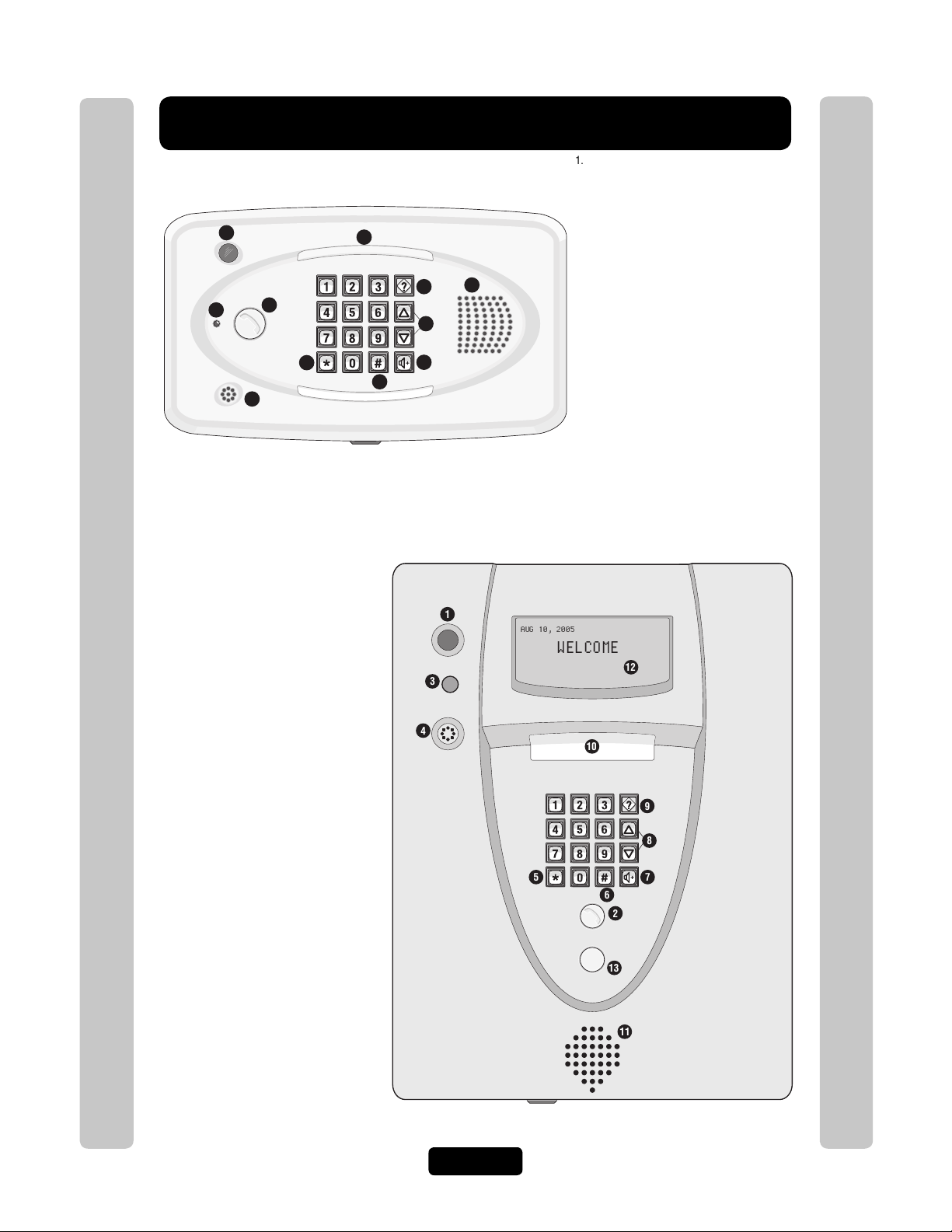
1. CCTV Camera: Optional
2. Call Button: Press to call a resident inside the
complex, or office.
3. Status LED: Solid Red (EL25 idle power, doors
are locked); Blinking Red (Strikes and Out for
a door); Solid Green (Granted access for a
door); Blinking Green (Latch for a door is
unlocked). NOTE: All references are for
door 1.
4. Microphone
5. Asterisk Key: "Start Programming Mode" or a
Cancel Key.
6. Pound Key: Data field separator, optional skip
step or enter key. Call a resident using the
directory codes.
7. Visitor Volume Key: Visitors can physically
adjust the speaker volume of the unit. Unit will
return to programmed volume setting when
transaction complete.
8. Up/Down Key: Serves no function on this unit.
9. Help Key: Receive a quick audio description of
a keypad button by pressing the Help key
followed by the key to be described.
10. Lights: Top and Bottom of Keypad.
11. Speaker: Allows resident and visitors to
communicate; plays responses to
communicate programming or function
commands.
Keypad Programming Guide
1. CCTV Camera: Optional
2. Call Button: Press to call a resident inside the
complex, or office. Also when calling someone
using the directory code listing.
3. Status LED: Solid Red (EL2000 idle power,
doors are locked); Blinking Red (Strikes and
Keypad Programming Guide
Out for a door); Solid Green (Granted access
for a door); Blinking Green (Latch for door 1 is
unlocked). NOTE: All references are for
door 1.
4. Microphone
5. Asterisk Key: "Start Programming Mode" or a
Cancel Key.
6. Pound Key: Data field separator, optional skip
step or enter key. Call a resident using the
directory codes.
7. Visitor Volume Key: Visitors can physically
adjust the speaker volume of the unit. Unit will
return to programmed volume setting when
transaction complete.
8. Up/Down Key: For scrolling through tenant
listing.
9. Help Key: Receive a quick audio description of
a keypad button by pressing the Help key
followed by the key to be described.
10. Lights: Top of Keypad.
11. Speaker: Allows resident and visitors to
communicate; plays responses to
communicate programming or function
commands.
12. LCD Display (optional)
13. Postal Plug
Page 1
Page 3
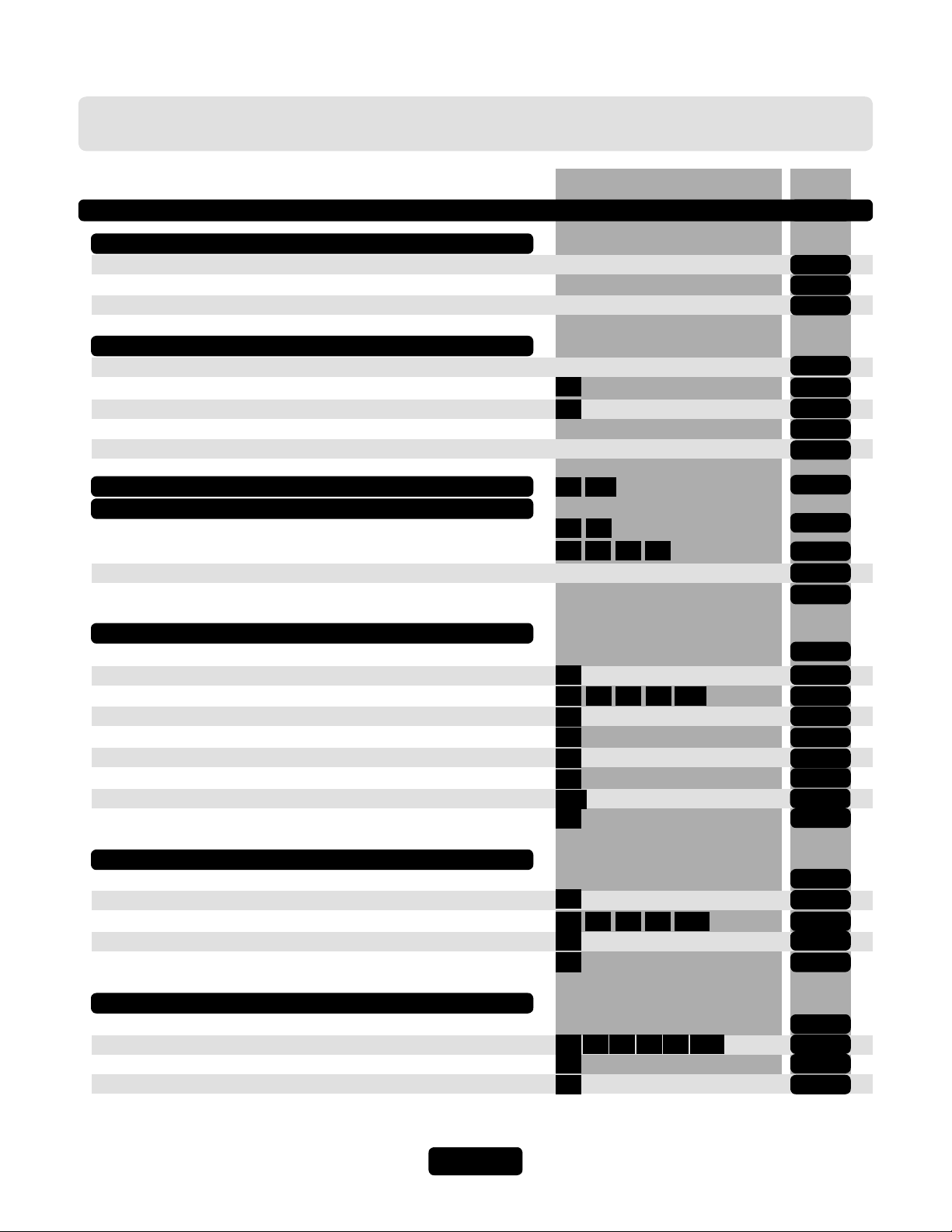
Table of Contents
Programming Numbers Page
Quick Reference Guide (Default Factory Settings)
Introduction
Single Family Residence (NPB)
Multi-Resident Complex (Dial-Out or Manager Sharing)
Sample Layouts and Your System Layout
Programming Single Unit Overview
Programming
Enter Programming Mode
Exit Programming Mode
System Feedback / Responses (Beeps)
Sending Direct Commands from Resident's Phone
Getting Started
Setup External Access Control Devices
Your Door Settings with Examples
Example
About Directory Codes
Set a Directory Code Length
Add, Edit, or Delete Directory Codes
Enable or Disable Do Not Disturb Schedule
Enable or Disable Call Forwarding (Directory Calls)
Add/Modify Resident DnD and/or Call Forwarding
Activate or Deactivate a Directory Code
Directory Code Display Option
Verify a Directory Code
Basics
Programming Multiple Units Overview
Setup “Your Settings”
Setups
Directory Codes
“ALL”
+ 6-Digit Password
***
0
2
111
1 3
60
666561
6
40 484441
201
10
46
49
45
141
47
4-8
9
9-10
11-13
14-15
16
16
17-18
19
20
21
22-24
25
26-27
28
29
29-31
31
31
32
32
33
33
Entry Codes
About Entry Codes
Set an Entry Code Length
Add, Edit, or Delete Entry Codes
Activate or Deactivate an Entry Code
Verify an Entry Code
Access Cards
About Cards
Add, Edit, or Delete Cards
Activate or Deactivate a Card
Verify a Card
Page 2
7
50 575451 202
56
55
80 858281 203
88
87
86
34
35
35-38
38
38
39
40-42
42
43
Page 4
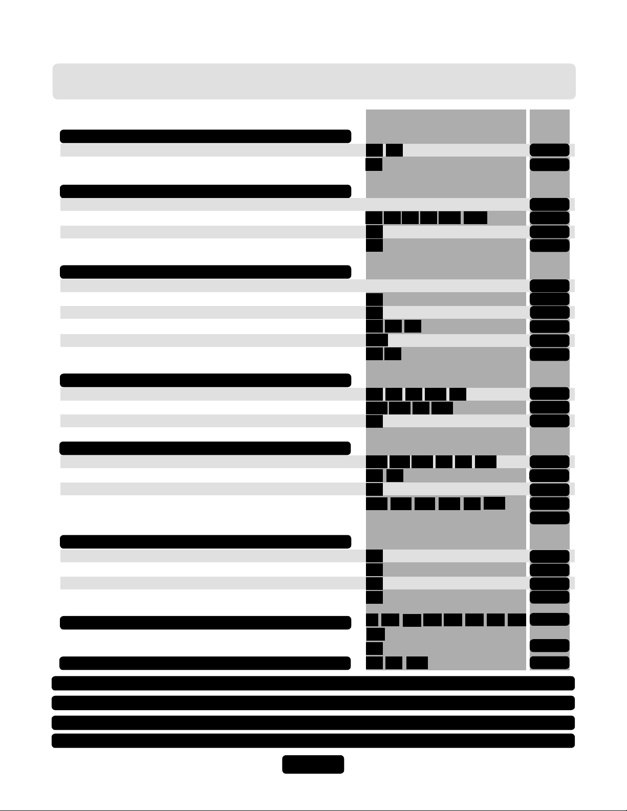
Table of Contents
Access Cards (Continued)
Facility Codes
Card Types
Transmitters (Remotes)
About Transmitters (Remotes)
Add, Edit or Delete Transmitter Codes
Activate or Deactivate a Transmitter
Verify a Transmitter
Time Zones, Holidays and Clock
About Time Zones
Creating Time Zones
Setting Holidays
Assigning Door Use and Unlock Time Zones
Deleting ALL Time Zones
Setting the Clock
Features
Setting Anti-Passback
Configuring the Alarm Features
Changing or Verifying the Unit Password
Programming Numbers Page
73
74
71
90
91
94
95
100
204
98
96
30
32
11
3163
205
3
4
10564 13
12
58
17102 103 104
1
43
43
44
45-47
48
48
49
50
50
51
52
52
53-54
54-56
56
Communications to and from Unit
Telephone-Unit Settings
Speaker-Microphone Settings
Enable or Disable Call Waiting
Visitor Communication Settings
LCD Visitor Messages
Postal Lock/Autocall/Exit/Door Sensor Devices
Postal Lock Switch
Autocall Device
Request to Exit Device (REX)
Door Sensing Devices
Direct Commands from the Phone
Real-Time Monitoring
Reset/Restore the Unit and Database
Keypad Template
Notes
Glossary
Appendix
18
9
69
70
67
68
21
131
24
28
109
19
22
126
57-59
59
59
60-61
62-63
64
64
65
66
67-69
70
71
72
73-74
75-76
77-78
16 110113115
20
160
26
121120
122
511623
123 124
125
20629
Page 3
Page 5
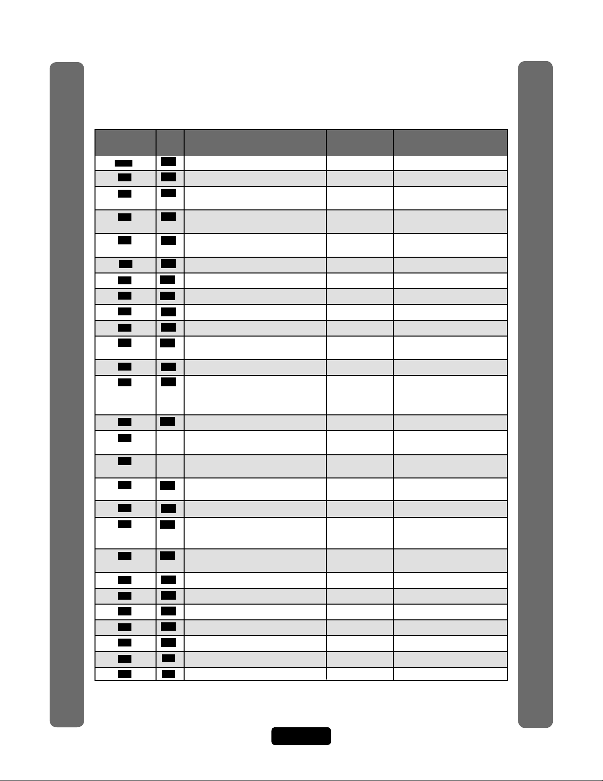
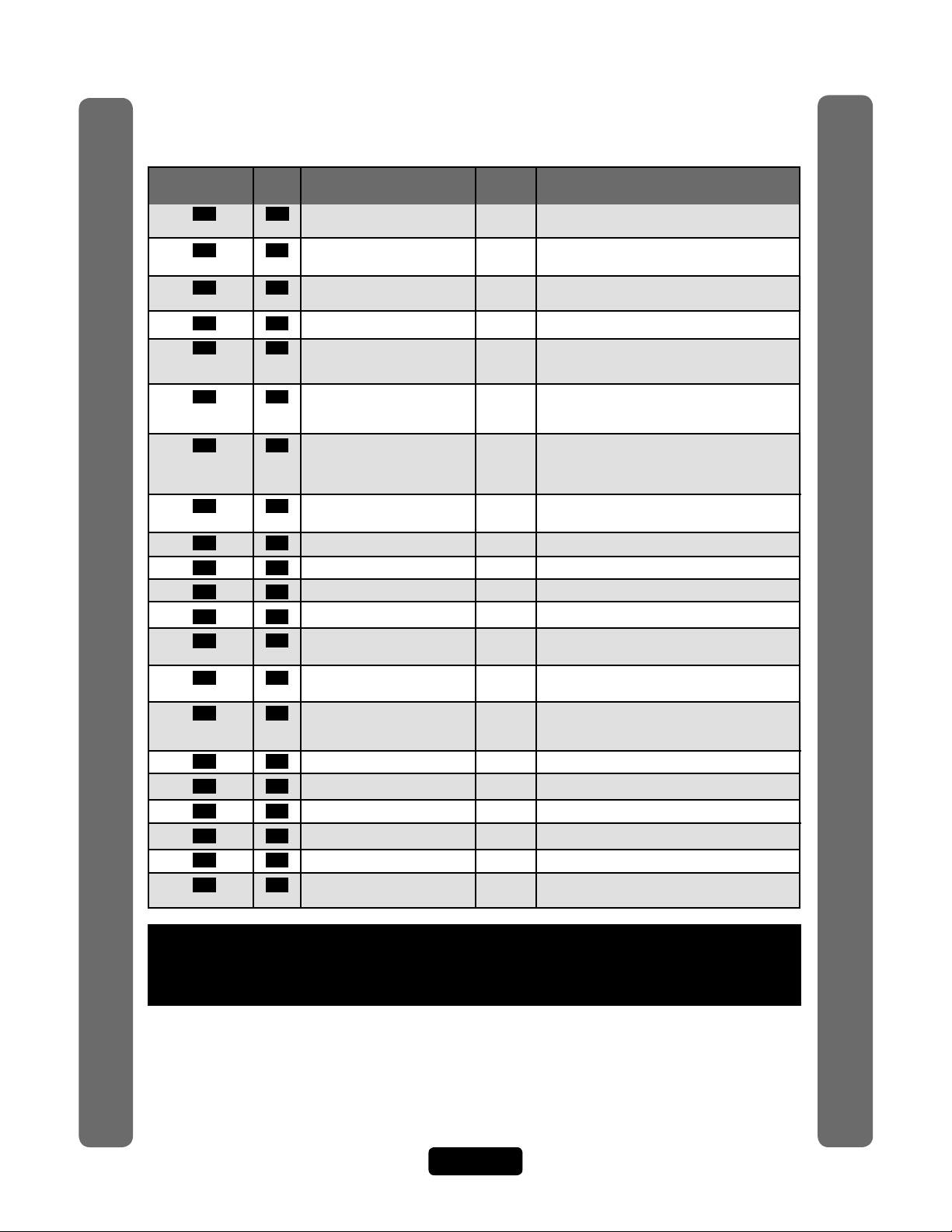
Quick Reference
Guide for Keypad Programming the Units
Programming
Number
15 Entering Programming Mode *** (6 Digit Password)
***
0 15 Exiting Programming Mode 0 #
1 56 Change or Verify the Unit’s Password 000000 1 # (1 to change; 2 to verify) #
2 20 Set Unit ID Number and No. in Chain Unit ID 1, 2 # (unit ID number, 1-7) #
Chain No. 1 (Number of Units in Chain, 1-7) #
3 52 Set the Clock 3 # yymmdd # (day of the week)
4 52 Enable/Disable Daylight Savings Time Enabled 4 # (0=disable; 1=enable) #
5 61 Set Visitor Talk Time 60 Seconds 5 # (15-250 seconds) #
6 29 Set Directory Code Length 3 Digits 6 # (1-4 ) #
7 35 Set Entry Code Length 4 Digits 7 # (3-9) #
9 59 Enable/Disable Call Waiting Enabled 9 # (0=disable; 1=enable) #
10 31 Enable/Disable Do Not Disturb Schedule Disabled 10 # (directory code) #
11 51 Enable/Disable Unlock Time Zone Enabled 11 # (0=disable; 1=enable) #
12 53 Enable/Disable Anti-Passback Disabled 12 # Enable/Disable True Anti-
13 53 Set Anti-Passback Time 3 Minutes 13 # (1-60 minutes) #
14 Set Maximum Number of Rings 5 Rings 14 # (1-9) #
Allowed Before Aborting Attempt
15
Ring Response 1=double ring) #
16 58 Number of Rings Before Unit Answers 5 Rings 16 # (0-15) # Each unit in chain
17 55 Set "Strikes" and "Out" 3 Errors 17 # (max errors, 0-5) #
18 59 Set Call Volume 5, 2, 2 18 # (0=mute; 1-10, 1 is low and
Quick Reference Guide
Set Voice Response Volume 10 is high) # (0=mute; 1=low;
Set Beep Response Volume 2=medium; 3=high) # (0-3) #
19 59 Set Microphone Volume 5 19 # (0=mute, 1-10, 1 is low and
20 58 Enable/Disable the Telco Mode Enabled 20 # (0=disable; 1=enable) #
21 67 Enable/Disable Direct Commands Enabled 21 # (0=disable, 1=enable) #
22 60 Enable/Disable Voice Mail Disabled 22 # (0=disable, 1=enable) #
23 60 Enable/Disable Access Granted Beeps Enabled 23 # (0=disable, 1=enable) #
24 70 Enable/Disable Real-Time Monitoring Disabled 24 # (0=disable, 1=enable) #
25 61 Return to Menu Programming 25 #
26 61 Enable/Disable All Door Access Granted Disabled 26 # (0=disable, 1=enable) #
Important: The Pound Key (#) must be used as Data Field Separator and to Save Data at the end of the
sequence. Time must be entered using a 24-hour format (8AM=0800, 3PM=1500 etc.). If you make an
error during an entry, press the asterisk key (*) to begin again.
Set Standard Single Ring or Double 1=Double Ring 15 # (0-1; 0=one long ring,
Page Description of Task
Optional Steps Indicated in BOLD type, all other steps are Required
Factory
Setting
Programming
Procedure
(six-digit coded) #
# hhmm #
(0=disable; 1=enable) #
Passback (0=disable; 1=enable) #
Enable/Disable Timed AntiPassback (0=disable; 1=enable) #
must have same setting
10 is high) #
Page 4
Quick Reference Guide
Page 6
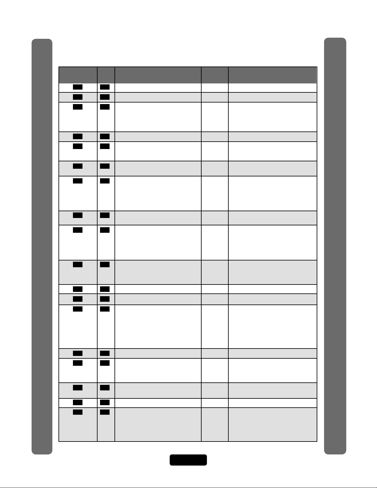
Quick Reference
Programming
Number
28 71 Restore Factory Settings 28 # 101010 #
29 71 Reset the Unit 29 # 101010 #
30 50 Create a Time Zone 30 # (time zone number, 2-63) #
31 51 Assign Door Auto Lock/Unlock Schedule Disabled 31 # (door 1-4) # (time zone, 2-63; 99) #
32 50 Setting Holidays 32 # (1=add, 2=verify, 0=delete) #
40 29 Add a Basic Directory Code Enabled 40 # (directory code) # (phone number) #
41 30 Add or Edit a Full Function Directory Code 41 # (directory code) # (phone number) #
44 30 Change a Directory Code ONLY 44 # (new directory code) # (directory
45 32 Activate/Deactivate a Directory Code 45 # (directory code) # (0=deactivate;
46 31 Enable/Disable Call Forwarding Disabled 46 # (directory code) # (0=disable;
(Directory Calls) 1=enable) # (schedule number, 0-63) #
(new call forward phone number) #
(call forward phone extension) #
47 33 Verify a Directory Code 47 # (directory code) #
48 30 Delete a Directory Code 48 # (directory code) #
49 31 Enable/Disable Call Forwarding and Do Disabled 49 # DnD Enable (1)/Disable (0) # DnD
Not Disturb Schedule with Schedule (0-63) # Call Forward
Residence "Call Button" Only Enable/Disable (0=disable; 1=enable) #
Page Description of Task
Quick Reference Guide
50 35 Add a Basic Entry Code 50 # (entry code) #
51 36 Add/Edit a Full Function Entry Code 51 # (entry code) # (schedule for door 1,
54 36 Change Entry Code ONLY 54 # (entry code to change) # (new entry
55 38 Verify an Entry Code 55 # (entry code) #
56 38 Activate/Deactivate an Entry Code 56 # (entry code) # (0=deactivate;
Factory
Setting
Programming
Procedure
(segment number; 99) # (starting
time=hhmm; 99) # (ending time=hhmm) #
(day of week, 1-8; 1=Sunday; 7=Saturday;
8=holiday) #
(yymmdd; yy=year, mm=month, dd=day
of the month) #
(phone extension) #
(phone ext) # (DnD schedule number,
0-63) # (enable/disable call fwd) # (call
fwd schedule number, 0-63) # (new call
fwd phone number) # (call fwd
phone ext) #
code to change) #
1=activate) # (0=don’t use start; 1=use
start) # (Start Date=yymmdd) # (Start
Time=hhmm) # (0=don’t use end; 1=use
end) # (End Date=yymmdd) # (End
Time=hhmm) #
Call Forward Schedule (schedule
number, 0-63 # (new call forward
phone number) # (call forward phone
extension) # (call forward extension
delay, 0 to 30 sec.) #
0-63) # (schedule for door 2, 0-63) #
(schedule for door 3, 0-63) # (schedule
for door 4, 0-63) #
code) #
1=activate) # (0=don’t use start; 1=use
start) # (Start Date=yymmdd) # (Start
Time=hhmm) # (0=don’t use end; 1=use
end) # (End Date=yymmdd) # (End
Time=hhmm) #
Quick Reference Guide
Page 5
Page 7
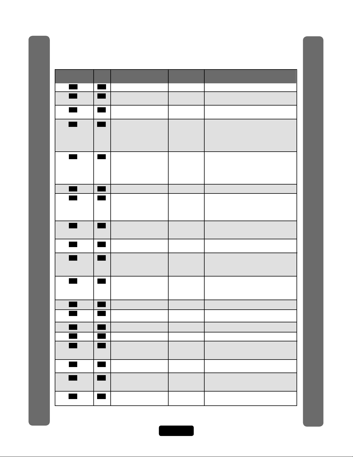
Quick Reference
Programming
Page Description of Task
Number
57 34 Delete an Entry Code 57 # (entry code) #
58 37 Assign Utility Option Off 58 # (entry code) # (Option; 0=Off, 1=Daily,
59 37 Assign Special Use 59 # (entry code) # enable/disable #
Entry Code
60 24 Assign Each External Main keypad 60 # (device 1-4) # (door 1-4) #
Access Control assigned door1
Device a "Door Number" Device 1=door 1
Device 2=door 2
Device 3=door 3
Device 4=door 4
61 24 Assign "Each" Door D1=Relay 1 61 # (door 1-4) # (relays to activate
Number to One or D2=Relay 2 0000-1111) # Order of relay is: relay 4-relay
More Relays D3=Relay 3 -3 -relay 2-relay 1 for an example if you
D4=Relay 4 want relay 4 active you would enter
1000, if you want relay 1 active you would
enter 0001
63 51 Assign Door Use Time Zone Enabled 63 # (door 1-4) # (time zone, 0-63) #
64 53 Set Anti-Passback Entry/Exit Disabled 64 # (device 0-4) #
for Specific Devices (0-3; 0=disable, 1=set device to timed
anti-passback, 2=set device to true
anti-passback-entrance, 3=set device for true
anti-passback-exit) #
65 23 Set Each "Relay Mode" All Relays= 65 # (relay 1-4) # (1-5; 1=strike, 2=shunt,
to get the "1-Strike" 3=CCTV, 4=alarm, 5=control) #
Appropriate Response
66 23 Set Each Relay’s All Relays= 66 # (relay 1-4) # time (1-300 seconds)
"Activation Time" 10 seconds
67 65 Request to Exit Device (REX) R1=Door 1 67 # (REX number 1-4) # (select REX option:
R2=Door 2 0=disabled, 1=use your door settings or 2=use
R3=Door 3 specific relay(s) 0000-1111) #
R4=Door 4 Order of Relays are 4321
68 66 Door Sensing Devices DS1= Door 1 68 # (sensor number 1-4) # (select sensor
DS2= Door 2 option: 0=disabled, 1=use your door settings or
DS3= Door 3 2=use specific relay(s) 0000-1111) #
DS4= Door 4 Order of Relays are 4321
69 64 Postal Lock Switch Door 1 69 # (door 0-4; 0=no postal lock) #
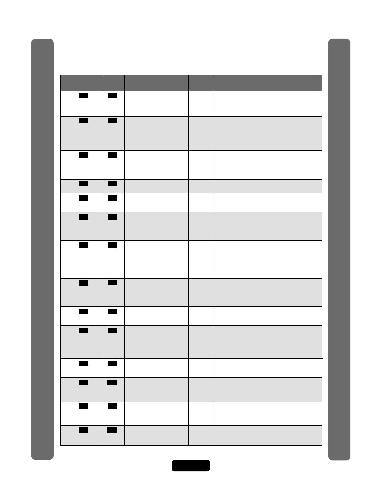
Quick Reference Guide
70 64 Autocall Device 0000 70 # (relays to activate 0000-1111) #
Order of relays are 4321 (Factory Default: 0000)
71 43 Set the Default Card Type 30 71 # (26 or 30) # (Factory Default: 30)
73 43 Set the Default Facility Code 0 73 # (0-255) #
74 43 Enable or Disable Ignore Enabled 74 # (0=disable; 1=ignore) #
Facility Code when
a Card is Used
75 36 Change Entry Code All Doors 75 # (entry code) # (door 0=any door,
Door Access
78 40 Change Card Code All Doors 78 # (card code) # (facility code) # (card type,
Door Access 26 or 30) # (door 0=any door, 1=door 1,
2=door 2, 3=door 3, 4=door 4) #
80 40 Add a Basic Card 80 (card PIN code) # (facility code) # (card
Factory
Setting
Programming
Procedure
2=Weekly, 3=Never) # (number of uses 1-15)
1=door 1, 2=door 2, 3=door 3, 4=door 4) #
type, 26 or 30) #
Quick Reference Guide
Page 6
Page 8
Quick Reference
Programming
Number
81 41 Add or Edit a 81 # (card PIN code) # (facility code) (card type,
Full Function Card 26 or 30) # (schedule for door 1, 0-63) #
82 41 Add a Group of 82 # (card PIN code start range) # (card PIN code
Cards at Once end range) # (facility code) # (card type, 26 or 30)
87 42 Activate or 87 # (card PIN code) # (facility code) # (card type,
88 42 Delete a Card 88 # (card PIN code) # (facility code) #
90 45 Add a Basic Transmitter 90 # (transmitter PIN code) # (facility code) #
91 46 Add or Edit a Full All Doors= 91 (transmitter PIN code) # (facility code) #
Access number) # (schedule for door 1, 0-63) # (schedule
for door 2, 0-63) # (schedule for door 3, 0-63) #
(schedule for door 4, 0-63) #
94 46 Add or Edit a Group of 94 # (transmitter PIN code start range)
code) # (sequence number) # (ID number)
# (button number) # (0=deactivate; 1=activate)
# (schedule for door 1, 0-63) # (schedule for door
2, 0-63) # (schedule for door 3, 0-63) # (schedule
for door 4, 0-63) #
95 47 Replace a Lost 95 # (transmitter PIN to change) # (facility code) #
96 48 Verify a Transmitter 96 # (transmitter PIN code) # (facility code) #
98 48 Activate or Deactivate 98 # (transmitter PIN code) # (facility code) #
Quick Reference Guide
number) # (0=deactivate; 1=activate) # (0=don’t
use start; 1=use start) # (Start Date=yymmdd)
# (Start Time=hhmm) # (0=don’t use end; 1=use
end) # (End Date=yymmdd) # (End Time=hhmm) #
100 47 Delete Transmitter 100 # (transmitter number) # (facility code) #
102 54 Configure "Door Held Disabled 102 # (alarm option; 0=disable, 1=enable until
103 55 Configure "Door Forced Disabled 103 # (alarm option; 0=disable, 1=enable until
104 55 Configure "Strikes Disabled 104 # (alarm option; 0=disable, 1=enable until
a Transmitter
Open” Alarm Feature
Open” Alarm Feature
and Out” Alarm Feature
Page Description of Task
Deactivate a Card
Function Transmitter 1 Full (sequence number) # (ID number) # (button
Full Function Transmitters
Transmitter
Factory
Setting
(schedule for door 2, 0-63) # (schedule for door
3, 0-63) # (schedule for door 4, 0-63) #
# (0=deactivate, 1=activate) # (schedule for door
1, 0-63) # (schedule for door 2, 0-63) # (schedule
for door 3, 0-63) # (schedule for door 4, 0-63) #
name (0-20 characters) #
26 or 30) # (0=deactivate; 1=activate) # (0=don’t
use start; 1=use start) # (Start Date=yymmdd) #
(Start Time=hhmm) # (0=don’t use end; 1=use end)
# (End Date=yymmdd) # (End Time=hhmm) #
(card type, 26 or 30) #
(sequence number) # (ID number) # (button
number) #
# (transmitter PIN code end range) # (facility
(sequence number) # (ID number) # (button
number) # (new transmitter PIN) # (new facility
code) # (new sequence number) # (new ID number)
# (new button number) #
(sequence number) # (ID number) # (button
number) #
(sequence number) # (ID number) # (button
(sequence code) # (ID number) # (button
number) #
relay time expires, 2=enable until alarm clears) #
(relay group, 0000-1111) #
Order of relays is 4321
relay time expires, 2=enable until alarm clears) #
(relay group, 0000-1111) #
Order of relays is 4321
relay time expires, 2=enable until alarm clears) #
(relay group, 0000-1111) # Order of relays is 4321
Programming
Procedure
Quick Reference Guide
Page 7
Page 9
Quick Reference
Programming
Page Description of Task
Number
105 54 Enable or Disable Anti-Passback Enabled 105 # (0=disable; 1=enable) #
Forgiveness at Midnight
109 58 Override Telephone Disabled 109 # (0=no; 1=yes) # Default is “No”
110 59
111 20
113 58 Dial "0-9" First to Get Disabled 113 # (0=disable; 1=enable) #
Automated Phone System
115 57 Set Alternative Prefixes Normal 115 # (normal-00, mixed-01, asterisk-02,
116 60 Change the Visitor 9,5,3, 116 # (activate door 1) # (activate door 2) #
access) #
120 67 Talk through the 120 #
121 68 Cycle Door 121 # (door 1-4) #
122 68 Toggle Door Open/Close Until 122 # (door 1-4) # (end time=hhmm) #
123 68 Get Door Status 123 # (door 1-4) #
124 68 Release Door 124 # (door 1-4) #
125 68 Enable/Disable Call Forwarding 125 # (0=disable; 1=enable) #
126 68 Enable/Disable Do Not Disturb 126 # (0=disable; 1=enable) #
141 33 Directory Code Display Option/ 0, 1, 141 # (directory code) # (hidden attribute option) #
201 31 Delete ALL Directory Codes
202 38 Delete ALL Entry Codes 202 # 101010#
203 42
204 47 Delete ALL Transmitter Codes
Quick Reference Guide
205 52 Delete ALL Time Zones
206 71 Delete ALL Access 206 # 101010#
an Outside Line Using a
toggle) # (extend talk time) # (hang up and deny
EL Models Speaker
Codes from Database
Company Answering Service
Set a Phone Number’s No Delays 110 # (directory code) # (phone extension
Extension Delay Time delay) # (call forward extension delay) #
Verify Unit Number 111 #
Call Response Keys 7,2,1,* (activate door 3) # (activate door 4) # (call wait
Residence
For
Residence
For
Resident Display Option 2 or 3
Delete ALL Cards
Factory
Setting
Programming
Procedure
(0-9, when enabled) #
pound-03, number-1n) # each unit in chain must
have same setting
(hidden option; 0=show name and code, 1=name
only, 2=code only, 3=hide) #
201 # 101010#
203 # 101010#
204 # 101010#
205 # 101010#
Quick Reference Guide
To enter programming mode from the keypad
Press *** and the 6-Digit Password (audio feedback will be heard)
Exiting programming mode allows changes to take effect
Important:
• The Pound Key (#) must be used as Data Field Separator and to Save Date at the end
of the sequence.
• Time must be entered using a 24-hour format (8AM=0800; 3PM=1500 etc.).
• Audio Feedback: Programming input is valid. Audio Feedback: Input is not valid.
• If you make an error during an entry, press the asterisk key (*) to begin again.
Page 8
Page 10
Introduction
Telco Phone Line
Bypass
Board
AUG 10, 2005
WELCOME
Telco Phone Lines
Phone Junction Box
Building/Complex
Resident
Resident
Resident
Manager
separate phone number
separate phone number
separate phone number
separate phone number
separate phone number
AUG 10, 2005
WELCOME
The sample installations on the next few pages will help familiarize you with the
features of your unit. You MUST know how your system is laid out to program it
with this manual. If you have questions about your configuration, please contact your
installing dealer for more information.
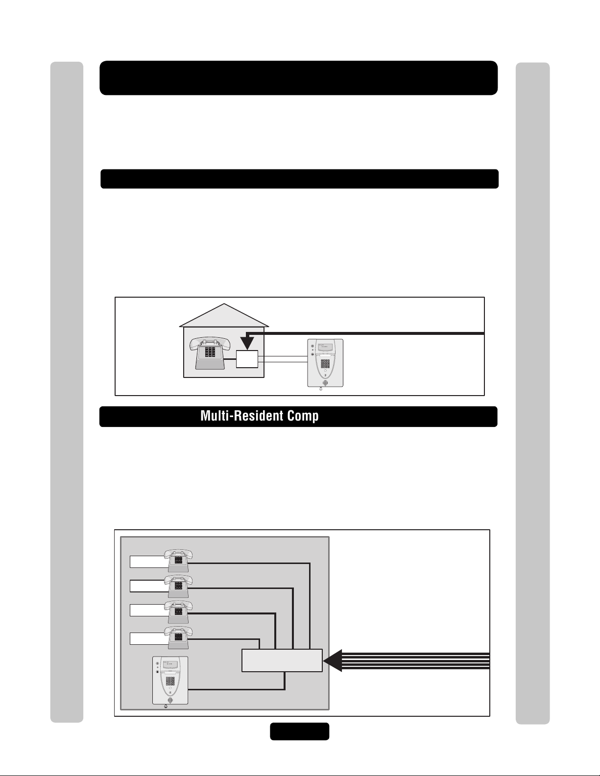
Single Family Residence (NPB)
This type of installation utilizes the "No Phone Bill" (NPB) feature. When a visitor
contacts the resident at the unit, it does not dial a separate number to reach you in
your residence. The unit essentially functions as an intercom with your residence
phone. Therefore, the NPB does not require the use of directory codes, since the unit
will only need to ring a single telephone line to the house. When a visitor arrives,
they will simply press the unit’s "Call" button to contact the resident.
Introduction
Introduction
This installation utilizes the dial-out feature. Each resident has a separate phone
number. The unit dials the resident’s numbers using preprogrammed Directory
Codes. Because the unit dials a separate phone number to contact the resident, the
"Call Waiting" and "Direct Command" features will not work. The unit must be
remotely programmed.
Multi-Resident Complex (Dial-Out)
Page 9
Page 11
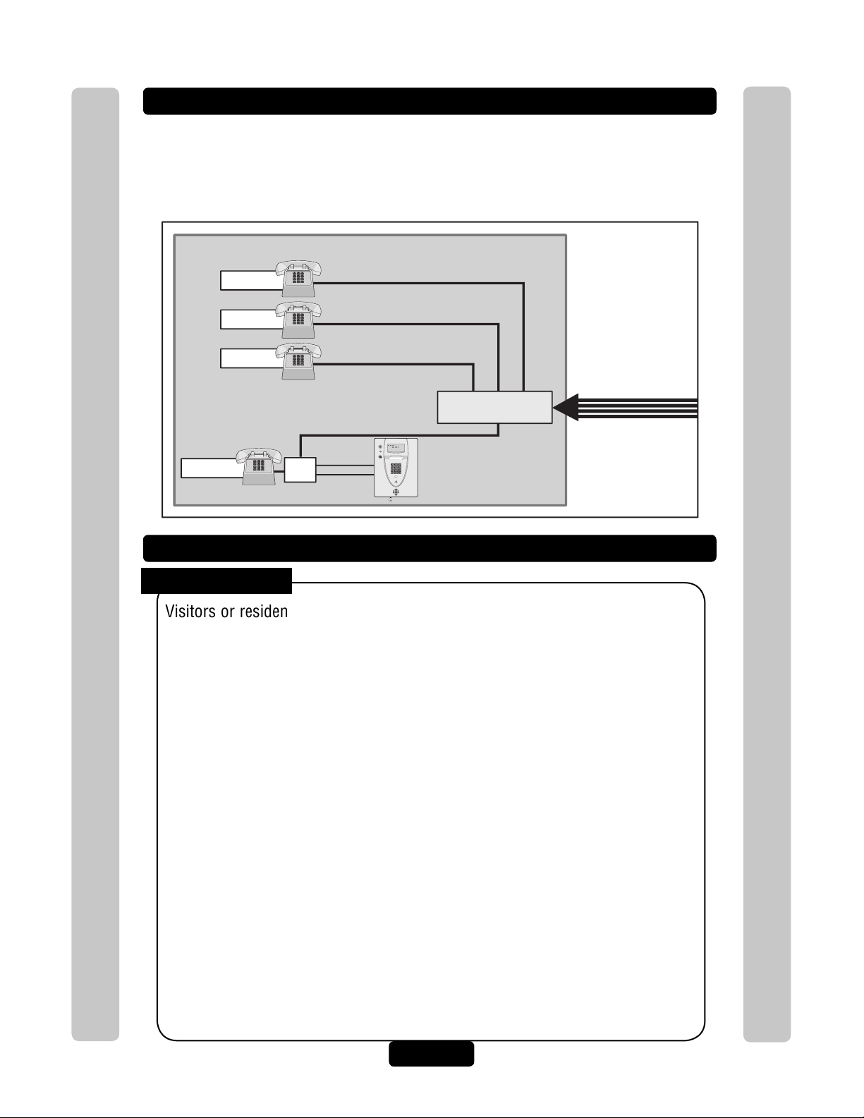
Multi-Resident Complex (Manager Sharing)
With this type of installation, the manager has the same features as the single family
residence (page 9). The unit can be programmed remotely or locally. Visitors can call
the manager directly using "Call" button or contact residents using preprogrammed
Directory Codes.
Building/Complex
Resident
separate phone number
Resident
Resident
Manager
Modes of Access
Visitors or residents of a building or complex controlled by a unit can gain
Introduction
access using one of the following methods:
Resident Phone (Directory Codes): A visitor may dial a resident’s
directory code from the unit to contact him/her. The resident can then
decide to grant or deny the visitor access to the building or complex.
separate phone number
separate phone number
Phone Junction Box
AUG 10, 2005
WELCOME
Bypass
Board
NPB Multi-Resident Complex
Telco Phone Lines
Introduction
Keypad (Entry Codes): A resident may enter a valid entry code on the
unit’s keypad or an optional external Wiegand-compatible keypad to enter
the building or complex.
Optional Card Readers (Cards): A resident may present a valid card
to an optional Wiegand-compatible card reader to enter the building or
complex. Card readers are typically located near an entry/exit area (e.g.,
door or gate).
Optional Radio Frequency Receivers (Transmitters): A resident
may choose to use an optional Passport radio frequency transmitter or
other optional Wiegand-compatible receiver to enter the building or
complex. For example, these may be used to open a vehicular gate.
Page 10
Page 12
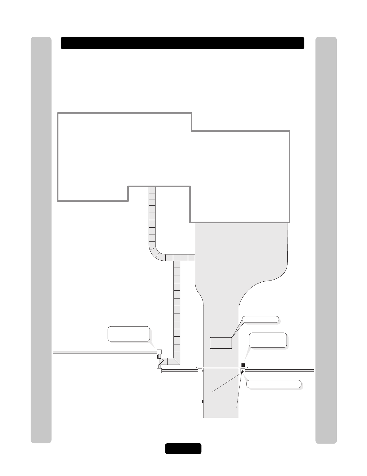
Single Family Residence (NPB) Example
EL Model System with optional CCTV
Card Reader
(Pedestrian Gate)
Gate Operator
(Vehicular Gate)
Relay 3 - Unlocks
Pedestrian Gate
Relay 1 - Opens
Vehicular Gate
Relay 2 - Turns on Light
Car Exit Sensor
Camera is always on.
The unit can operate the vehicular gate with an access code or by remote control. It
will allow Pedestrians entry with an Access Card. It will also open the gate
automatically for exiting cars.
Introduction
Introduction
Page 11
Page 13
Multi-Resident Complex Example
The unit can control the property with a vehicular gate operator, access card or the
unit’s keypad. Residents can use programmed transmitters for the parking lot,
access cards for the pool or a personal entry code for the main entrance. The main
entrance is equipped with a door sensor to alert management about inappropriate
use. The exit sensor will automatically open the gate for exiting cars.
Pool
Card Reader Relay 3
Opens Pool Gate
Card Reader
(Pool Gate)
Introduction
Parking Lot
Introduction
Car Exit Sensor
Gate Operator
(Vehicular Gate)
RF Receiver Relay 2
Opens Vehicular Gate
Relay 4 - Shunts Alarm
for Main Entrance
Manager's
Office
Internal Keypad Relay 1
Opens Main Entrance
EL Model
(Main Entrance)
Page 12
Page 14
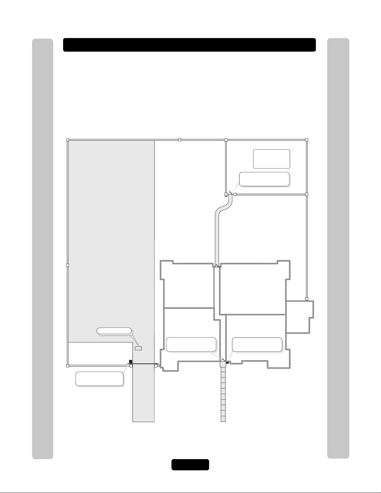
Your System Layout
How your system has been wired is an important part of programming it. Write down
your configuration. To help visualize it, draw a map of it below. If you’re unsure of
your setup, consult your dealer/installer for more information.
Introduction
Introduction
Door Stat 1
Connection
Door Stat 2
Connection
Door Stat 3
Connection
Door Stat 4
Connection
Door Sensor
and/or
Exit Device
Door Sensor
and/or
Exit Device
Door Sensor
and/or
Exit Device
Door Sensor
and/or
Exit Device
External Access Control Device(s) connected to aux board(s)
(Default Internal Keypad)
Device 0
Device 1
Device 2
Device 3
Device 4
Relay Connections
Relay 1
Relay 2
Relay 3
Relay 4
Autocall
Device
Postal
Lock
CCTV
Camera
Yes
No
Yes
No
Yes
No
Page 13
Page 15

Programming Single Unit Overview
Programming Basics
The units can be programmed 4 different ways:
1. Keypad: You may use the keypad on the front panel (next page).
2. Local/Remote DTMF Phone: You may use the keypad on a local or remote phone
to program the system. The unit responds to the DTMF signals generated by your
touch-tone phone (next page).
3. Direct/Modem Connection to a PC: In order to program the units with a direct or
modem connection, your PC must be running Chamberlain’s Windows®
compatible Versa XS software (not covered in this manual).
4. EL2000 Keypad with Display: On EL2000 units with an LCD, you have two ways
to use the LCD to program the unit.
1. Enter program steps and use the LCD to confirm the step(s) before entry or
2. Use the program menus in an interactive step-by-step manner to program
common items in the system.
Programming Single Unit Overview
When using the program menus, you’ll notice that they are fairly intuitive
and walk you through the common areas necessary to set up a basic
system. There is also a quick start menu selection, numerous help files
and voice and text confirmation of the areas programmed. Two areas
that do need special mention are noted below:
1. Scan Mode: This is a new feature that allows you to enter single transmitters or
cards by scanning them into the system. The program menus are the only area in
the system where you can use the scan mode feature.
2.
Programming Single Unit Overview
and keys and and keys for navigation and text input while
using the program menus. The up and down keys help you to scroll through the
alphabet for text input, while "4" and "6" numeric keys allow you to advance the
cursor forward or backward.
The best way to learn how to navigate through the menus is to actually
use them to program the standard settings in the system. You can use
the keypad programming template on page 72 for a description of the
keypad keys and functions.
Page 14
Page 16
Programming Single Unit Overview
g
1
Programming Basics
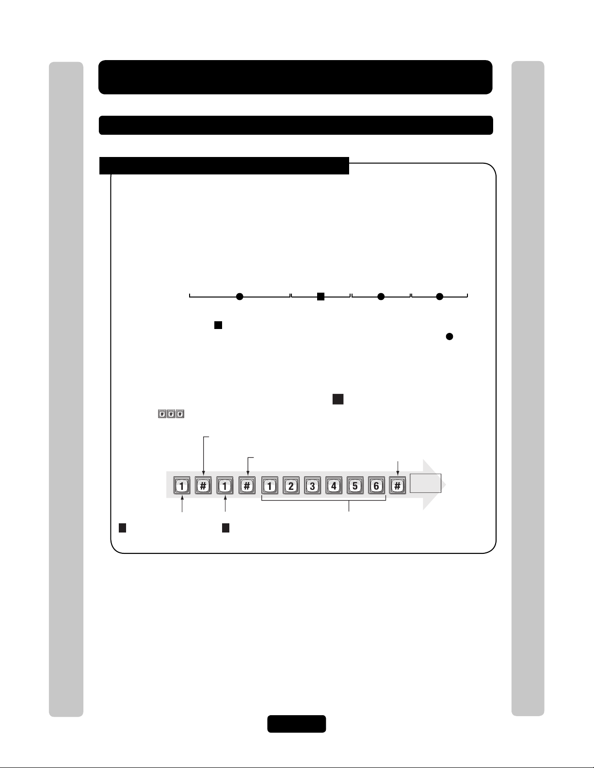
Procedure Required to Program EL Models:
1. 1,2 or 3 digit Programming Number. (See "Quick Reference Guide" Tables for descriptions
and procedures)
2. One or more Data Fields.
3. Pound Key (#) as a Data Field Separator and at the end of the programming sequence to Save
the Data.
NOTES:
• All data fields must be separated with the pound key (#).
Example: (Programming Number) # (Data Field) # (Data Field) # (Data Field) #
1 3 42
Required Step Optional Step Required Step Required Step
• Steps tagged with a ( ) are optional, press the pound key (#) to skip them. NOTE: Some
steps are required and must have data entered in them to continue, tagged with ( ).
• If you make an error during an entry, press the asterisk key (*) to cancel the step.
• When you correctly enter the entire programming sequence, the unit will respond with voice
feedback (see also System Feedback/Responses(Beeps) on page 16).
Programming Single Unit Overview
Example of a Programming Sequence: " Changing the Password"
NOTE: must be pressed first to enter programming mode
1st Pound Key:
Separates the 1st field.
Pound Key:
Separates the data field.
Enter
Programming
Mode
(Next page)
Programming Number:
1
Programming Single Unit Overview
changes or verifies
the password.
Data Field:
1
changes the password
(2 verifies the password)
1
Data Field:
(The new password)
Last Pound Key:
Saves the data.
Voice
feedback
Exit
Programmin
Mode
(Next page)
Page 15
Page 17
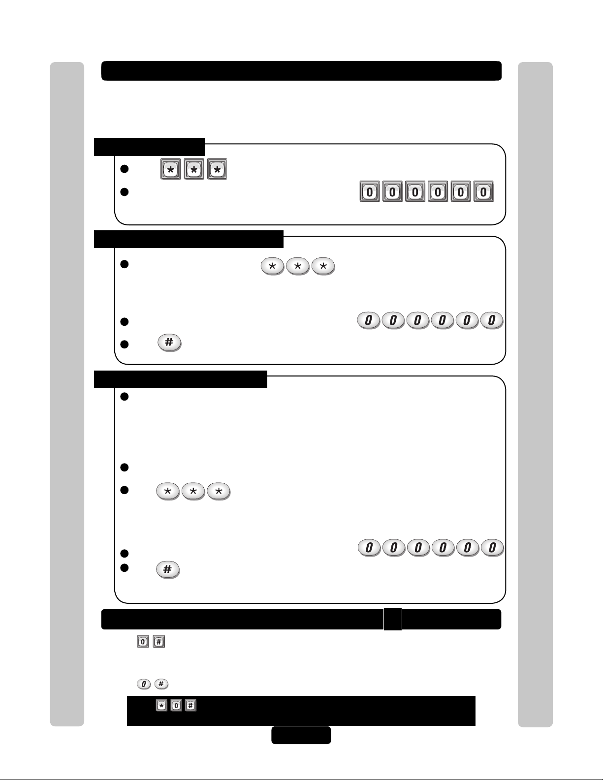
Enter Programming Mode
If you will be programming the unit via modem, please refer to the Versa XS online help.
***
Important: After entering programming mode for the first time, we suggest you change
the password to maintain the security of your system (see page 56).
From the Keypad:
1
Press
2
Enter the (6) six-digit password. The default is six zeroes.
Voice Feedback
The unit is now ready to accept programming instructions!
From the Residence Telephone:
1
When you lift the receiver, press
NOTE: If multiple units are sharing the same phone line, then a Unit ID Code (1-7) will need to be
entered at this time. See page 20 for more information about Multiple Unit Sites.
2
Enter the (6) six-digit password. The default is six zeroes.
3
Press and the audio tone will stop.
The unit is now ready to accept programming instructions!
Programming Single Unit Overview
From the Remote Telephone:
1
Dial the unit’s phone number:
Note: If the unit and an answering machine (or answering service) utilize the same phone line,
let the line ring at least (2) two times, hang-up, and call back within one (1) minute. The unit will
answer on the second call. If the unit does not answer, you may need to change the ring count
(see page 58).
2
When the unit picks up the call, you will hear the audio message: "Please enter password"
3
Press
NOTE: If multiple units are sharing the same phone line, then a Unit ID Code (1-7) will need to be
entered at this time. See page 20 for more information about Multiple Unit Sites.
Programming Single Unit Overview
4
Enter the (6) six-digit password. The default is six zeroes.
5
Press and the audio will stop.
The unit is now ready to accept programming instructions!
Exit Programming Mode
• Press on the unit keypad and the unit will respond with audio feedback when
disconnecting.
0
• Press on the telephone and the unit will respond with audio feedback when disconnecting.
Press
and exit programming mode.
when using a telephone or the unit to cancel programming sequence
Page 16
Page 18
System Feedback / Responses (Beeps)
The units emit various audio tones to respond to input and to indicate
certain conditions.
Programming Responses:
Voice Response Description
4 Short Beeps: Enter command System is waiting for a latch command
by user with entry code
3 Short Beeps: Exit program Exiting from program mode
2 Short Beeps: Valid step Valid step entered in programming mode
1 Long Beep: Invalid step Invalid step entered during programming
2 Long Beeps: Duplicate code Duplicate code entered during
programming a new code
3 Long Beeps: Capacity reached The new code is rejected because
database is full
1-7 Short Beeps: Unit 1-7 Give feedback of system ID number to
user in programming mode: keypad or
phone
1 Short Beep: Digit Keyname Echo each key press on user’s touch tone
phone or key press while in programming
mode
Programming Single Unit Overview
Other Response:
Voice Response Description
4 Long Beeps: Chime System starts up
Programming Single Unit Overview
Visual Responses:
LED Status Description
Solid Red Idle power, door 1 is locked
Blinking Red Strikes and Out for door 1
Solid Green Granted access for door 1
Blinking Green Latch for door 1 is unlocked
Page 17
Page 19
System Feedback / Responses (Beeps)
Direct Command Responses:
Voice Response Description
10 Short Beeps: Entrance 1-4 opened This is the command to latch open door 1
5 Short Beeps: Entrance 1-4 closed This is the command to keep the latch
closed for door 1
Visitor Responses:
Voice Response Description
10 Short Beeps: Access granted Access is granted from an entry code or
other code used on door 1. Access may
also be granted by a tenant on their touch
tone phone. The voice is played first then
the beeps
1 Long Beep: Access denied Access is denied from an entry code, card
code used or invalid password on door 1.
Access may also be denied by a tenant on
their touch tone phone
1 Long Beep: Invalid code Unknown entry or directory code on
door 1
2 Short Beeps: --- Indicates door 1 is already open
Busy Tones: --- Directory code in DND mode or resident line
is in use
1 Short Per Second: --- 1 beep is played per second for remaining
seconds during a call
2 Short Beeps: Program mode System acknowledges valid prefix/password
and is in program mode
Use up and down keys to While system is idle and the help key is
pressed
Programming Single Unit Overview
Programming Single Unit Overview
Page 18
Page 20
Sending Direct Commands from the Resident’s Phone
(NPB / Single Family Residence ONLY)
You can send commands directly to the unit from your phone without
being in programming mode. This feature is only available from a
single-family residence or a manager who is sharing a phone line with
the unit.
To Enter a Direct Command from a Residence Phone:
1
Lift the receiver and press
NOTE: If multiple units are sharing the same phone line, then a Unit ID Code (1-7) will need to be
entered at this time. See next page for more information about Multiple Unit Sites.
The unit is now ready to allow direct commands only!
Example 1:
Enters direct command mode
Example 2:
Enters direct command mode for unit three
Programming Single Unit Overview
Programming Single Unit Overview
Page 19
Page 21
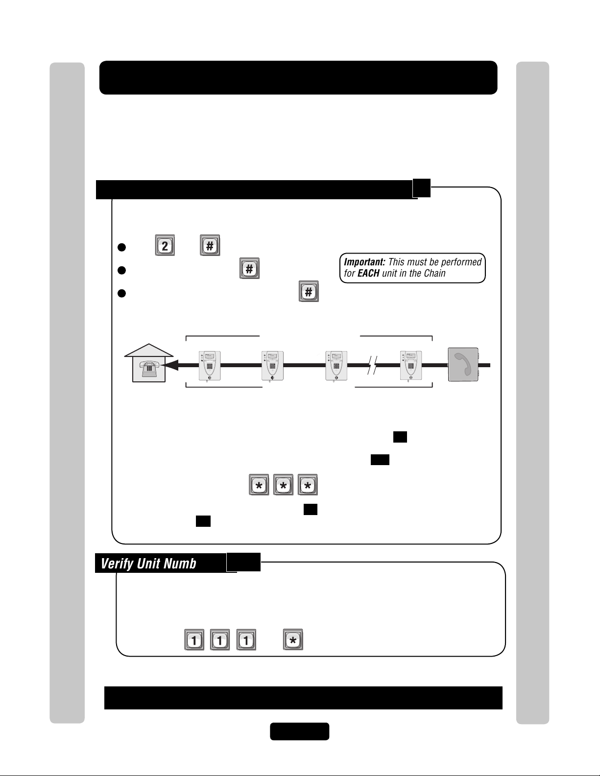
Programming Multiple Units Overview
Up to seven (7) units can be installed on a single telephone line. Each
unit must have a "Unique Unit ID" number and the "Number of Units in
Chain" assigned to it.
Set the Unit ID Number and Number of Units in Chain:
2
The unit ID identifies each unit within a chain. Adding or removing will require the unit ID’s to be
re-entered. Factory Setting: Unit ID 1 and Number of Units in Chain 1.
1
Press Then
2
Unit ID Number (1-7), Then
3
Total Number of Units in Chain (1-7), Then
Example:
Residence
Unit ID “1”
AUG 10, 2005
WELCOME
Unique Unit ID Sequencial Order
Unit ID “2”
AUG 10, 2005
WELCOME
Number of Units in Chain “7”
Important: This must be performed
for EACH unit in the Chain
Unit ID “3”
AUG 10, 2005
WELCOME
Unit ID “7”
AUG 10, 2005
WELCOME
Telco Entrance Box
Demarcation Point
Important:
You must program each unit ID using the main keypad first before attempting remote access.
EACH unit in the Chain must have the same "Rings Before Answer" 16 .
Factory Setting - 5 Rings
EACH unit in the Chain must have the same "Alternate Prefix" 115 .
Programming Multiple Units Overview
Factory Setting - Normal (use
to enter programming)
Be sure to set the rings before answer value 16 is greater than maximum rings before
aborting attempt 14 .
Programming Multiple Units Overview
Verify Unit Number:
This allows you to verify a unit’s number within a chain. When you perform this step, the unit will
respond with the number corresponding to its unit ID number. The message two (2), for
example, means the unit is number 2 in the chain.
If you make an error during an entry, press the asterisk key (*) to begin again.
111
Then
Page 20
Page 22
Setup “Your Settings”
The units come preprogrammed with Factory Settings. When the unit is
first installed, you DO NOT need to program each feature.
Review the unit’s factory settings before programming (see Quick
Reference Guide, pages 4-8 for ALL the Factory Settings).
Getting Started
Change the Unit Password:
Recommended
Change the unit password to prevent any tampering with your system’s database. When changing
the password, save a copy of it in a secure location. If you lose the password, you will not be
able to enter into programming mode. Factory Setting: 000000
See page 56
Set the Clock:
Recommended
An accurate clock is critical to the proper use of schedules and for accurately reporting
transactions.
See page 52
3
1
SetUP "Your Settings"
Change the Unit’s ID and Chain Number for Multiple
Unit Configurations ONLY:
SetUP "Your Settings"
2
Recommended
The Unit ID number identifies each unit within the chain. Setting the "Unit ID" and "Number of
Units in the Chain" are required so Versa XS can send or receive data to/from the correct units
within the chain. Factory Setting: Unit ID Number "1" and Number of Units in
Chain "1".
See previous page
Page 21
Page 23
Setup External Access Control Devices
The unit must have all external access control device options
configured into it, before many of the other programming options can
proceed. You must tell the unit "what it’s wired to" and "how you want
the devices to behave." To do this you must know what a "Door"
Number is and what a "Relay" is.
What is a Door Number?
A Number (1-4) YOU assign to the unit to identify the External Access Control Devices wired to it.
Up to 4 devices can be connected. Once identified, the unit will keep the Same Door Numbers in
other programming. The Internal Keypad is ALWAYS Assigned to Door Number 1.
What is a Relay?
SetUP "Your Settings"
A relay is a device that reacts to an electric current to activate other devices. Allowing the EL
Model to lock or unlock a door/gate, shunt (bypass) alarm contacts, signal an alarm, or turn on a
camera wired to a closed-circuit television (CCTV). The relays can be programmed to 5 different
modes.
The 5 Modes of Operation are:
Strike Relay: A Strike Relay controls a door or gate by unlocking or opening it. It does not
control any other component associated with a system like Alarms, CCTV, etc.
SetUP "Your Settings"
Shunt Relay: A Shunt Relay is normally wired to an alarm and works with strike relays to
shunt (bypass) the alarm when the door is opened with a valid access code. If the door is
forced open, the system will not shunt the alarm and the alarm will be triggered.
CCTV Relay: The camera is wired to a closed circuit television (CCTV). The system’s
camera is always on. The CCTV relay can be used to control an external recorder or external
camera.
Alarm Relay: The Alarm Relay will activate another device, such as a siren, when 3
conditions occur. A door is opened without a valid access code, a door is open past the
allotted time programmed in, or too many invalid codes are tried. Any of these will trigger the
alarm relay.
Control Relay: The Control Relay can control another device such as an outdoor or indoor
light near the unit. For example, you could configure the system to turn on an entry light
through a darkened area after a resident enters a valid access code. The light would then turn
off after a specified amount of time.
Page 22
Page 24
Configuring "YOUR" Unit:
There are 3 sample configurations on pages 26 and 27 to help you understand
the 4 step process needed to setup YOUR external access control devices.
Step 1
Step 2
Step 3
Step 4
Set Each Relay Mode for the Appropriate Response: There are 5 different relay modes
(Previous Page). The relay mode determines what the relay will control (a door, alarm,
CCTV, etc.). See next page.
Set Each Relay’s Strike Time: The relay time determines the amount of time the relay
remains activated. For example, when a strike relay activates to unlock a door, the relay
activation time determines how long the door will remain unlocked (next page).
Assign Each Door Number to One or More Relays: Defines which relays will activate
when a resident presents a valid access code to an external access control device
(next page).
Assign Each External Access Control Device to a Door Number: When a valid access
code is entered into a external access control device, the Assigned door’s relays will
activate (see below).
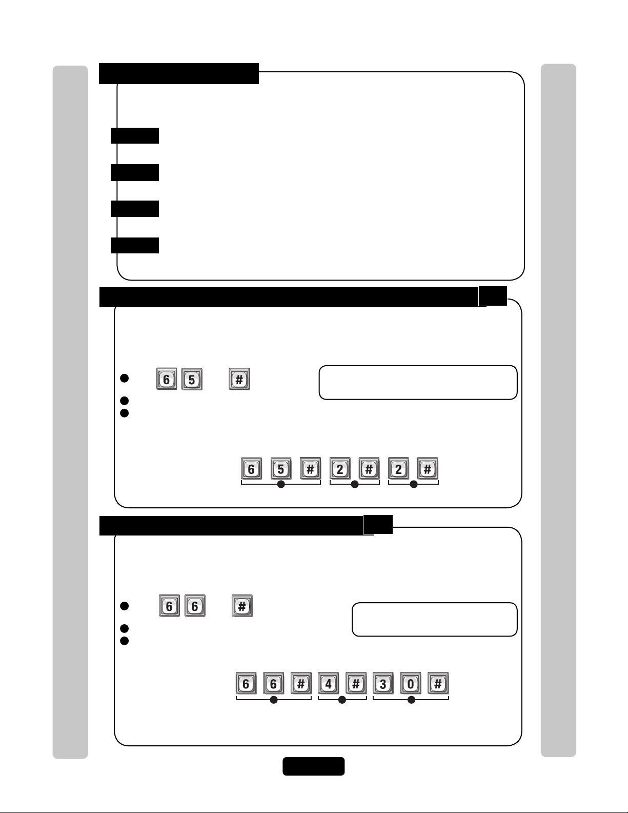
Step 1 Set Each "Relay Mode" to get the Appropriate Response:
There are 5 different relay modes (see page 22). The Relay Mode determines what the response
will be when a valid access code is entered (open a door, turn on an alarm, turn on a light then
turn it off, turn on a CCTV, etc.). Be sure relays are not activated when changing "Relay Mode"
types. Factory Setting: All Relays are Set at "1 - Strike"
1
Press
2
Enter the Relay Number (1-4). Then (#)
3
Enter Relay Mode (1-5). Then (#)
1 = Strike - controls a door/gate by unlocking/opening it. 4 = Alarm - activates another device (siren)
2 = Shunt - bypasses the alarm under normal 5 = Control - controls another device
circumstances. (on/off light)
Then
Important: 1-3 must be performed for EACH
Relay assigned to the unit.
65
SetUP "Your Settings"
Example:
1 2 3
SetUP "Your Settings"
Assigns Relay “2” as a Shunt Relay
Step 2 Set Each Relay’s "Activation Time":
This is the amount of time (in seconds) the relay remains activated. This will define the amount
of time a door cycles (unlocks, then relocks) or how long the CCTV camera remains on after
being activated. Be sure relays are not activated when changing relay "Activation Time".
Factory Setting: All Relays are set at 10 seconds.
1
Press
2
Enter the Relay Number (1-4). Then (#)
3
Enter Activation Time (1-300 Seconds). Then (#)
Then
Example:
1 2 3
When Activated, the Relay Number "4" will activate for "30" seconds.
NOTE: Most gate operators recommend activation of 2 seconds.
66
Important: 1-3 must be performed for
EACH Relay assigned to the unit.
Page 23
Page 25

Step 3 Assign "Each" Door Number to One or More Relays:
Device "1" is Assigned as Door "3".
Example A:
1 2 3
Device "3" is Assigned as Door "4".
Example B:
1 2 3
When a valid access code is used at an external access control device (Door), the unit can be set
to activate one or more relays.
Factory Settings: Door 1 Activates Relay 1; Door 2
61
Activates Relay 2; Door 3 Activates Relay 3; Door 4 Activates Relay 4
1
Press
2
Enter the Door Number (1-4). Then (#)
3
Enter Relays to be Activated (0000-1111). Then (#)
0=Deactivate, 1=Activate (1st digit=Relay 4, 2nd digit=Relay 3, etc.)
Example:
When a Resident uses a Valid Code at "Door 1", Relay "1" and Relay "2" will Activate
Then
1 2 3
Step 4 Assign Each External Access Control
Important: 1-3 must be performed
for EACH Door Number assigned to
the unit.
Relay 4 Relay 3 Relay 2 Relay 1
Deact Deact
Activate Activate
60
Device a "Door Number":
To perform these 4 steps you MUST know EXACTLY where the External
Access Control Device(s) are wired in "Your" unit! When page 13 and 23 are
completed by you or your installer, they will help you understand "Your"
personal layout. If you do not know this, DO NOT PROCEED. Consult your
Installer and/or refer to the installation manual for assistance.
The units can be equipped with Wiegand reader and radio frequency (RF) modules that allow
your system to accommodate external access control devices such as a Wiegand-compatible
card readers (keypad) and RF receiver. In order for Wiegand devices to work successfully, you
must assign them a "Door Number". When a valid access codes is presented to the device, the
Assigned Door’s Relays will activate. Factory Setting:
SetUP "Your Settings"
Main Keypad
Door 1 Door 1
SetUP "Your Settings"
1
Press Then
2
Enter External Access Control Device Number (1-4). Then (#)
Internal Keypad is ALWAYS Assigned to External Access Control Device Number 0
3
Assign a Door Number (1-4) to the Device. Then (#)
Device 1
Device 2
Door 2
Page 24
Device 3
Door 3
Important: 1-3 must be performed
for EACH external access control
device of unit.
NOTE: A "Door Number" is a
number you assign to each
external access control device.
Only Wiegand devices may be
assigned to a door.
Device 4
Door 4
Page 26

"Your" Door Settings
(See tables below for reference)
Device Location
When
"Your Door Settings"
Door
No.
or
Relay
"Door 1,2,3 or 4"
Relay
Mode
manual, this completed chart will outline how your unit will function.
Sample: The System Controlling 1 Door (Next Page for Illustration)
Device
Main Keypad
(REX) Exit Request
Sample: The System Controlling 2 Doors and a Vehicle Gate (Next Page for Illustration)
Device
Main Keypad and Postal Lock
SetUP "Your Settings"
Security Light
Wiegand Card Reader
Transmitter Buttons
Location Relay Relay Mode Relay Function Relay Activation Time (Seconds)
Front Door
Location Door No.
Front Door
Back Door
Gate Operator
Door No.
Door 1
Door 1
Door 2
Door 3
1 Strike Unlocks Door 10 sec.
2 Shunt Bypasses/Signals Alarm 40 sec.
3 Alarm Sounds a Siren 10 sec.
4 CCTV Activates Camera 10 sec.
Relay Relay Mode Relay Function Relay Activation Time (Seconds)
1 Strike Unlocks Door 10 sec.
2 Control Turns on Security light 60 sec.
3 Strike Unlocks Door 10 sec.
4 Strike Opens Gate 10 sec.
Relay
Function
Relay Activation
Time (Seconds)
are referenced throughout this
SetUP "Your Settings"
Sample: The System Controlling 4 Doors (Page 27 for Illustration)
Device
Main Keypad
Wiegand Keypad
Wiegand Card Reader
Wiegand Card Reader
Location Relay Relay Mode Relay Function Relay Activation Time (Seconds)
Front Door (Entrance)
Front Door (Exit)
Back Door
Manager’s Door
Door No.
Door 1
Door 2
Door 3
Door 4
1 Strike Unlocks Door 10 sec.
2 Strike Unlocks Door 10 sec.
3 Strike Unlocks Door 10 sec.
4 Strike Unlocks Door 10 sec.
Sample: The System Controlling Single Family Residence (Page 11 for Illustration)
Device
Main Keypad and
(REX) Exit Request
Wiegand Card Reader
CCTV
Location Door No. Relay Relay Mode Relay Function Relay Activation Time (Seconds)
Driveway
Pedestrian Gate
In EL Model System
Door 1
Door 2
Door 3
1 Strike Opens Vehicular Gate 10 sec.
2 Control Turns on Security Light 10 sec.
3 Strike Unlocks Pedestrian Gate 10 sec.
4 CCTV Activates Camera 10 sec.
Sample: The System Controlling Multi-Resident Apartment (Page 12 for Illustration)
Device
Main Keypad
Transmitter and REX Exit Device
Wiegand Card Reader
Siren
Location Relay Relay Mode Relay Function Relay Activation Time (Seconds)
Front Door (Entrance)
Vehicular Gate
Pool Gate
Front Door (Entrance)
Door No.
Door 1
Door 2
Door 3
Door 4
1 Strike Unlocks Door 10 sec.
2 Strike Unlocks Door 10 sec.
3 Strike Unlocks Door 10 sec.
4 Shunt Bypasses/Signals Alarm 30 sec.
Page 25
Page 27

Unit Controlling 1 Door
Relay 1 - Strike Mode
Unlocks Door for 10 sec.
Relay 3 - Alarm Mode
Sounds Siren for 10 sec.
Relay 2 - Shunt Mode
Bypasses/Signals Alarm
for Maglock for 40 sec.
Relay 4 - CCTV Mode
Activates External
Camera or Recorder
(not system’s camera)
Main Keypad
(Front Door)
REX Device
(Exit)
Relay 2 - Control Mode
Turns on Security Light
for 60 sec.
Main Keypad
(Front Door)
Card Reader
(Back Door)
Transmitter
(Gate Operator)
Relay 1 - Strike Mode
Unlocks Door for 10 sec.
Relay 3 - Strike Mode
Unlocks Door for 10 sec.
Relay 4 - Strike Mode
Opens Gate for 10 sec.
Postal
Lock
SetUP "Your Settings"
Unit Controlling 2 Doors and Vehicle Gate
SetUP "Your Settings"
Page 26
Page 28

Unit Controlling 4 Doors
Card Reader
(Back Door)
Relay 3 - Strike Mode
Unlocks Door for 10 sec.
SetUP "Your Settings"
Wiegand Keypad (Exit)
Relay 2 - Strike Mode
Unlocks Door for 10 sec.
Exit
Enter
Main Keypad
(Front Door)
Relay 1 - Strike Mode
Unlocks Door for 10 sec.
Card Reader
(Manager's Door)
Relay 4 - Strike Mode
Unlocks Door for 10 sec.
SetUP "Your Settings"
Page 27
Page 29

Directory Codes
Building Directory
Floyd A. D.
Gates H. B.
Lyle A. T.
Monroe S. Y.
Priest J. A.
Warren B. K.
01
02
03
04
05
06
Name
Directory
Code
Enter the Directory Code on the unit's keypad then press
Visitor uses Directory Code to contact Resident Resident can grant access to Visitor Visitor gains entry
About Directory Codes
Directory Codes are unique 1-4 digit codes that dial a corresponding
telephone number in the building. When a visitor wishes to contact a
resident, the visitor enters the Directory Code on the unit’s keypad. The
unit will dial the phone number assigned to the code. The resident can
then talk to the visitor by phone and grant them entry into the building.
To Use an Existing Directory Code to Contact a Resident:
Directory Codes
Directory Codes
Before adding or modifying Directory Codes, answer the following questions:
• Have you chosen the Directory Code number you will assign? This number will be assigned to a resident. The visitor
will enter this number on the unit keypad to prompt the system to dial the resident’s phone number.
• Do you know the resident’s phone number? The system needs the phone number so it can dial the resident when
prompted. If the resident’s phone has an extension, the unit will need that data as well.
• Will the resident want a Do Not Disturb schedule? If the resident doesn’t want to be disturbed during certain times,
you can configure his/her Directory Code with a Do Not Disturb schedule. During this schedule, visitors won’t be able
to call the resident. See page 31.
• Will the resident utilize a Call Forwarding number during certain times? Perhaps the manager of an apartment
complex wants the leasing office phone number forwarded to an answering service after 5PM on weekdays and all
day on weekends. See page 31 for more information.
• Will you activate or deactivate the Directory Code at a certain day and time? You may assign a Directory Code to a
resident and delay its use until a day and time you specify. Also you can deactivate the Directory Code on a specified
day and time. See page 32.
• For units with an LCD display, you can control how the tenant’s name is displayed on the screen. See
page 33.
Page 28
Page 30

Set Directory Code Length
1 2
3A
Example:
Adds Directory Code "12" with phone number "555-8978". The phone extension field was skipped.
3
Factory Setting: 3
1
Press Then
2
Enter New Directory Code Length (1-4). Then (#)
Example:
Makes Directory Code length 2 digit Maximum.
Important: You will not be able to decrease the Directory Code length if codes already
exist that are more than the attempted decrease length. For example, you will not be able
to decrease a code from 2 digits to 1 digit if 2-digit codes already exist.
You will not be able to increase Directory Code length if there’s an entry code length
conflict.
If you increase the Directory Code length, all existing codes will increase with leading
zeroes for every digit increase. For example, if you increase the length to 2 digits, an
existing Directory Code of 4 will now be 04.
Add, Edit or Delete Directory Codes
6
1 2
Directory Codes
When adding or editing Directory Codes, note the following:
• Keep a record of each Directory Code you assign; in particular, write down the resident names
associated with each code. This will help when adding, editing, or deleting Directory Codes later.
• Each assigned Directory Code must be entered with the set amount of allowable digits (up to 4).
Directory Codes
For example, if you assign "2" as a resident’s Directory Code, but the system is set for two digits, the
visitor will have to enter "02" to call the resident.
Add Basic Directory Code:
Add a Directory Code, Phone Number, and Phone Extension.
1
Press
2
Enter Directory Code (up to 4 digits). Then (#).
3
Enter Phone Number (up to 20 digits). Then (#).
3A
Phone Extension if necessary (up to 5 digits). Then (#).
Then
40
NOTE: A basic Directory Code will be active, have a do not disturb schedule of "0"
(i.e., resident can be called 24 hours a day, 7 days a week), and have no call forwarding.
Page 29
Page 31

Add or Edit Full Function Directory Code:
2
Example:
4 5 6 7 88A
3
1
Do Not Disturb Schedule = 0
Call Forwarding Enable or Disable = 0
Call Forwarding Schedule = 0
Factory
Settings
1 2 3
Changes Directory Code from "14" to "23".
Example:
1 2
Deletes Directory Code "23".
Example:
When adding a full function Directory Code, it will default as "active". To deactivate a code, or
deactivate on a specific time and date, see Activate or Deactivate Directory Code on page 32.
41
1
Press
2
Enter Directory Code (up to 2 digits). Then (#)
3
Enter Phone Number (up to 20 digits). Then (#)
4
Enter Phone Extension (up to 5 digits). Then (#)
5
Enter Do Not Disturb Schedule (0-63). Then (#)
0 = May always be disturbed
1 = Never disturb
6
Enable (1) or Disable (0) Call Forwarding. Then (#)
Adds Directory Code "45" with phone number "555-2134", phone extension "432", uses Do
Not Disturb schedule 2 and disables call forwarding.
Change a Directory Code ONLY:
Then
44
7
Enter Call Forward Schedule (0-63).
Then (#)
0=Never Use Call Forward Number
1=Use Call Forward Number
8
Only Enter New Call Forward Phone
Number (up to 20 digits). Then (#)
(Skip this step to keep existing Call
Forward Phone Number).
8A
Enter Call Forward Phone Extension
(up to 5 digits). Then (#)
(If using an extension the unit MUST
have a phone number).
Directory Codes
Allows you to change ONLY the Directory Code without affecting the other data associated
with the record (e.g., phone number, do not disturb schedule, etc.).
1
Directory Codes
Press
2
The New Directory Code Number (Up to 4 digits). Then (#).
3
The Current Directory Code number (Up to 4 digits). Then (#).
Delete a Directory Code:
1
Press
2
Enter the Directory Code number to be deleted (Up to 4 digits). Then (#)
Then
48
Then
Page 30
Page 32

1 2 3
Disables the Do Not Disturb schedule for Directory Code "34".
Example:
Delete ALL Directory Codes:
1 2
Enables Call Forwarding number 555-3662 for Directory Code "14" with a use schedule of "2".
Example:
3 4 5 5A
Factory
Settings
Call Forwarding Enable or Disable = 0
Call Forwarding Schedule = 0
This will delete ALL Directory Codes from unit.
I mportant: Once you delete the Directory Codes, you cannot retrieve them unless they are
saved in Versa XS.
1
Press
2
Enter
Then
Then
201
Enable or Disable Do Not Disturb Schedule
10
Do Not Disturb (DnD) Schedules prevent visitors from calling residents during
specified time frames. To assign a DnD Schedule to a Directory Code, use the
programming step for adding/editing a full function Directory Code (see page 29).
When enabling/disabling DnD Schedule for a Directory Code, the system will
remember the schedule assigned to the code. Factory Setting: Disabled
1
Press Then
2
Enter the Directory Code to be enabled or disabled. Then (#)
3
Enable (1) or Disable (0). Then (#)
Enable or Disable Call Forwarding (Directory Calls)
Call Forwarding redirects visitor calls to another telephone number instead of the
Directory Codes
regular phone number. During a Call Forwarding call, the visitor will hear normal
telephone line sounds but will not hear the number being dialed.
You can Enable or Disable the Call Forwarding Feature for a specific Directory Code
(Dial-Out). Factory Setting: Disabled
Directory Codes
46
1
Press
2
Enter Directory Code (1-4 digits). Then (#).
3
Enable (1) or Disable (0). Call Forwarding. Then (#).
3
Enter Call Forward Schedule (0-63). Then (#)
0=Never Use Call Forward Number
1=Use Call Forward Number
Then
Page 31
5
Only Enter New Call Forward Phone
Number (up to 20 digits). Then (#)
(Skip this step to keep existing Call
Forward Phone Number)
5A
Enter Call Forward Phone Extension (up to
5 digits). Then (#)
(If using an extension the unit MUST have
a phone number).
Page 33

1 2 3
Directory Code "33" is Activated on February 1st, 2004 at 6PM.
Example:
Year Month Day
24-Hour Time
4
5
4A
4B
5B
5A
Add / Modify Resident DnD and/or Call Forwarding
76A65432
Example:
1
49
Add/Modify DnD and Call Forwarding Information for the Resident (NPB) or manager. Do
Not Disturb (DnD) Schedules prevent visitors from calling the Resident (NPB) or manager
phone during specified time frames. Call Forwarding redirects visitor calls to an outside
telephone number instead of ringing the Resident (NPB) or manager phone. During a Call
Forwarding call, the visitor will hear normal telephone line sounds but will not hear the
number being dialed.
You can Enable or Disable, individually, the DnD and Call Forwarding features for the
Resident (NPB) or manager phone. Factory Setting: DnD Control Setting is Disabled (0);
Call Forwarding Control Setting is Disabled.
6
1
Press
2
Set DnD Control Setting, Enabled (1) or
Then
Disabled (0). Then (#).
3
Enter Do Not Disturb Schedule (0-63).
Then (#).
4
Set Call Forward Control Setting, Enabled (1)
or Disabled (0). Then (#)
5
Enter Call Forward Schedule (0-63). Then (#)
Only Enter New Call Forward Phone Number (up to
20 digits). Then (#)
(Skip this step to keep existing Call Forward Phone
Number)
6A
Enter Call Forward Phone Extension (up to 5 digits).
Then (#)
(If using an extension the unit MUST have a phone
number).
7
Enter Call Forward Extension Delay (0-30 sec.).
Then (#)
Directory Codes
The DnD Control Setting is Enabled and uses Schedule "34". It also Enables Call Forwarding which uses
Schedule "22". Call Forwarding uses Phone Number "976-5000" with Extension "1136" and waits "20"
seconds before dialing the Extension.
Activate or Deactivate a Directory Code
45
Activate or deactivate Directory Codes. Also activate or deactivate specific dates and
times for those Directory Codes.
Directory Codes
Activate / Deactivate a Directory Code:
Disabling the Activate Directory Code
Activate Directory Code
1. If you disable the Start Activation Date
times, the Directory Code will immediately become active and stay that way until the code is deactivated or
deleted.
2. If you enable the Start Activation Date 4 and add only a "Start Date and Time"
End Deactivation Date
3. If you disable the Start Activation Date
Date and Time"
4. If you enable the Start Activation Date
Deactivation Date
"Start Date and Time" and deactivate on the "End Date and Time".
3
, then the four If statements could apply:
5
, the Directory Code will activate on that "Start Date and Time".
5A
, the Directory Code will deactivate on that "End Date and Time".
5B
5
and add an "End Date and Time"
To Activate or Deactivate a Directory Code:
1
Press Then
2
Enter Directory Code (1-4 digits). Then (#)
3
Activate Directory Code, (Enable-1 or Disable-0). Then (#)
4
Use Start Activation Date, (Enable-1 or Disable-0). Then (#)
3
, the Directory Code will always be deactivated. If you enable the
4
and disable the End Deactivation Date 5 and omit all dates and
4B and disable the
4A
4
and enable the End Deactivation Date 5 and add only an "End
4
and add a "Start Date and Time"
5A
, the Directory Code will activate on that
5B
4A
Start Date (yymmdd). Then (#)
4A 4B
enable the End
4B Start Time (hhmm). Then (#)
5
Use End Deactivation Date, (Enable-1
or Disable-0). Then (#)
5A End Date (yymmdd). Then (#)
5B End Time (hhmm). Then (#)
NOTE: All time must be entered using a
24-hour format (8AM=0800, 3PM=1500 etc.)
Page 32
Page 34

Directory Code Display Option
141
Directory Code must exist in the unit’s database. Factory Setting: 0, 1, 2 or 3
1
Press Then
2
Enter Directory Code. Then (#)
3
Enter Hidden Attribute Option (0-3). Then (#)
Option 0=Show All (always show name and directory code number).
Option 1=Show Name (only shows name on the tenant list in the display).
Option 2=Show Code (only shows the code on the tenant list in the display).
Option 3=Hide (does not show the name or the code in the tenant list-tenant is skipped in the display).
Resident Display Option
141
To modify how the resident is displayed use Step 141, however skip entering the
directory code. Also, note that only options 1 and 3 are allowed, because the resident
does not have a directory code. Factory Setting: 1
1
Press Then
2
Press (#)
3
Enter Hidden Attribute Option (1 or 3). Then (#)
Option 1=Show Name (only shows name on the tenant list in the display).
Option 3=Hide (does not show the name or the code in the tenant list-tenant is skipped in the display).
Directory Codes
Directory Codes
Page 33
Page 35

Entry Codes
About Entry Codes
Entry Codes are programmable, numeric codes (3-9 digits in length) that
allow entry or exit through a gate/door. Residents enter their assigned
entry code onto the unit’s keypad to prompt the system to grant access.
To use an existing Entry Code:
On the unit’s keypad, enter the assigned "Entry Code". If you make a mistake entering the code,
press .
Entry Codes
Entry Codes
Resident keys in personal Entry Code Grants Entry
Before adding or modifying Entry Codes answer the following questions:
• Have you chosen the Entry Code number you will assign? This number will be assigned to
a resident. The resident will enter this number on the unit of the keypad to prompt the
system to grant access.
• Will the Entry Code have a use schedule (a.k.a. Time Zone)? You may assign a schedule
to an Entry Code so that is valid only during specified time frames.
• What schedules will the Entry Code use at each door? You may assign a schedule at each
door that a resident may enter through.
• Will an entry code be used for a pre-defined number of uses? You can assign a utility
option to control the number of uses for an entry code.
• Will the entry code use action codes? You may assign special use on an entry code. Special
use entry codes execute an action at the main keypad.
Page 34
Page 36

Makes Entry code length 5 digit maximum.
Example:
1 2
Set an Entry Code Length
Example:
Adds Entry Code "5400".
21
Factory Setting: 4 Digits
1
Press Then
2
Enter New Entry Code length (3-9 digits). Then (#)
Important: You will not be able to decrease the Entry Code length if codes already exist that
are more than the attempted decrease length. For example, you will not be able to decrease
a code from 5-digits to 4-digits if 5-digit codes already exist.
If you increase the Entry Code length, all existing codes will increase with leading zeroes for
every digit increase. For example, if you increase the length to 5 digits, an existing Entry
Code of 4556 will now be 04556. This value correlates with directory code length. The entry
code length must always be one (1) digit greater than the directory code length.
You will not be able to decrease the Entry Code length if it conflicts with the Directory Code
length.
7
Entry Codes
Add, Edit or Delete Entry Codes
When adding or editing entry codes, note the following:
• Keep a record of each Entry Code you assign. In particular, write down the resident names
associated with each code. This will help when adding, editing or deleting Entry Codes later.
• Each assigned Entry Code must be entered with the set amount of allowable digits (3-9). For
Entry Codes
example, if you assign "4578" as a resident’s Entry Code, but the system is set for 5 digits, the visitor
will have to enter "04578" to enter the building.
Add a Basic Entry Code:
Add an Entry Code ONLY. For adding or editing full function Entry Codes (i.e., codes with
additional options such as use schedules, door assignments, etc.). See next page.
1
Press Then
2
Enter Entry Code (3-9 digits). Then (#)
50
NOTE: Factory Setting for Entry Code
Length is 4 digits (See “Entry Code
Length” above)
NOTE: A basic Entry Code will be active and unlock all controlled doors, with no time constraint
(i.e., can be used 24 hours a day, 7 days a week).
Page 35
Page 37

Add or Edit Full Function Entry Code:
Example:
Door 3Door 2Door 1
3
4 5
Door 4
6
1 2
Enables entry code "5400" to activate doors 1 & 2 on schedule #2 and restricts access to doors 3 & 4.
Changes entry code from "6543" to "3456".
Example:
1 2 3
When adding a full Function Entry Code, it will default to "Active" at the current date and time
with no deactivation date. To deactivate a code, or to activate or deactivate on a specific time
and date, see Activate or Deactivate Entry Code on page 38.
1
Press Then
2
Enter Entry Code (3-9 digits). Then (#)
3
Schedule for Door 1 (0 to 63). Then (#)
0=Full Restrictions 1=Full Access
4
Schedule for Door 2 (0 to 63). Then (#)
0=Full Restrictions 1=Full Access
51
5
Schedule for Door 3 (0 to 63). Then (#)
0=Full Restrictions 1=Full Access
6
Schedule for Door 4 (0 to 63). Then (#)
0=Full Restrictions 1=Full Access
Factory Settings: All Doors = 1 Full Access
Change Entry Code ONLY:
Change only the Entry Code without affecting the other data associated with the code (e.g.,
schedule, door assignment, etc.). For example, you change only the code and keep the
resident’s existing schedule and door assignment because unauthorized individuals have been
using that resident’s code.
1
Press Then
2
The Current Entry Code Number (3-9). Then (#)
3
The New Entry Code Number (3-9). Then (#)
Entry Codes
Delete an Entry Code:
1
Press Then
2
Enter the Entry Code number to be deleted (3-9 digits). Then (#)
Change Entry Code Door Access:
54
Entry Codes
57
75
Change which doors or single door an entry code activates. By default new entry codes can
open any door, use this step to have the code open a specific door.
1
Press Then
2
Enter the Entry Code number (3-9 digits). Then (#)
3
Enter 0 for access at any door. Enter 1,2,3 or 4 for specific door access.
If you make an error during an entry, press the asterisk key (*) to begin again.
Page 36
Page 38

Assign Utility Option:
Entry Code "1394" has 1 use resetting weekly for direct commands from the keypad.
Example:
89
1 2
3
4
Entry Code "1394" has the ability to execute an action at the main keypad.
Example:
99
1 2
3
Assign a limited use entry code. This feature allows the user to assign a fixed number of uses
for an entry code. The number of uses may reset daily or weekly. For example, allow a
temporary code use 4 times a day. Use the never reset option to give a fixed use until all tries
are used up. Factory Setting: Off
1
Press Then
2
Enter new or existing entry code (3-9). Then (#)
3
Option:
0=Off
1=Reset use daily at midnight
2=Reset weekly
3=Never reset
4
Number of uses (1-15)
58
Assign Special Use Entry Code at the Unit Keypad:
Table of responses for Action Codes: Voice is the primary response, if there is no voice then
beeps are played. When you hold down the last digit, you will hear “command” and then you
enter one of the command numbers.
Command Number Action
0 Release all Doors and return to previous schedule
1 Toggle Open/Close for Door 1
2 Toggle Open/Close for Door 2
Entry Codes
3 Toggle Open/Close for Door 3
4 Toggle Open/Close for Door 4
5 Toggle Enable/Disable Resident Call Forward
6 Toggle Enable/Disable Resident Do Not Disturb
7 Get Door Status (Rolling). Each use reports status of next door. For
* The Open status means the door is currently opened by a Latch Command or in the Unlock
portion of an Automatic Schedule.
** The commands 5 and 6 play a single short beep when enabled or a single long beep when
disabled.
1
Press Then
2
Enter existing entry code (3-9) and hold down last digit for command prompts. Then (#)
3
Enable/Disable special use. Then (enable = 1, disable = 0) (#)
59
Entry Codes
example used once the status may report door 1, used again then status
reports door 2, etc.
NOTE: You may not assign utility codes with special use ability. When you hold down the last
digit, you will hear “command” and then you enter one of the command numbers.
Page 37
Page 39

Delete ALL Entry Codes:
This will delete ALL Entry Codes from unit.
I mportant: Once you delete the Entry Codes, you cannot retrieve them unless they are saved
in Versa XS.
1
Press Then
2
Enter Then
202
Activate or Deactivate an Entry Code
This allows you to activate or deactivate an Entry Code, also on a specific date and time.
Activate / Deactivate an Entry Code:
Disabling the Activate Entry Code
Entry Code 3, then the four If statements could apply:
1. If you disable the Start Activation Date
times, the Entry Code will immediately become active and stay that way until the code is deactivated or
deleted.
2. If you enable the Start Activation Date
Deactivation Date 5, the Entry Code will activate on that "Start Date and Time".
3. If you disable the Start Activation Date 4 and enable the End Deactivation Date 5 and add only an "End
Date and Time"
4. If you enable the Start Activation Date
Deactivation Date
and Time" and deactivate on the "End Date and Time".
To Activate or Deactivate an Entry Code:
Entry Codes
1
Press Then
2
Enter Entry Code (3-9 digits). Then (#)
3
Activate Entry Code, (Enable-1 or Disable-0). Then (#)
4
Use Start Activation Date, (Enable-1 or Disable-0).
Then (#)
, the Entry Code will deactivate on that "End Date and Time".
5B5A
5
and add an "End Date and Time"
, the Entry Code will always be deactivated. If you enable the Activate
3
4
and disable the End Deactivation Date 5 and omit all dates and
4
and add only a "Start Date and Time"
4
and add a "Start Date and Time"
5B5A
, the Entry Code will activate on that "Start Date
4A
Start Date (yymmdd). Then (#)
4B Start Time (hhmm). Then (#)
5
Use End Deactivation Date, (Enable-1
or Disable-0). Then (#)
5A End Date (yymmdd). Then (#)
5A
End Time (hhmm). Then (#)
NOTE: All time must be entered using a
24-hour format (8AM=0800, 3PM=1500 etc.)
56
4B4A
and disable the End
4B4A
enable the End
Entry Codes
Verify an Entry Code
Verify that an Entry Code exists in the unit’s database.
Audio Feedback "Invalid Step": Indicates the code Does Not exist in the database.
Audio Feedback "Valid Step": Indicates the code Exists in the database.
1
Press Then
2
Enter Entry Code (3-9 digits). Then (#)
If you make an error during an entry, press the asterisk key (*) to begin again.
Page 38
55
Page 40

Access Cards
About Cards
Access cards allow entry or exit through a gate/door. This feature allows
residents to swipe a card into a card reader (other card types and card
readers may apply) to prompt the system to grant access.
Access Cards
Access Cards
Resident uses Card Reader Grants Entry
Before adding or modifying cards, answer the following questions:
• Do you know the card’s number? Each card will have a pre-defined number. You must enter the card’s
number into the system when assigning a card.
• Do you know each card type you will assign? The system must know the type of card that will be used
(e.g., Standard 26-bit or Sentex 30-bit). You may assign a default card type if all of your cards are the
same type (see also page 43). If you don’t know the card type, check with the card manufacturer or
your installing dealer.
• Do the cards have a Facility Code? These codes allow cards to be associated with a facility or
complex. This feature is useful if you manage more than one complex. You may also assign a default
facility code if a group of cards will share the same code (see also page 43).
NOTE: Cards may have the same card code as long as their Facility Codes differ and/or the
cards are a different type.
• What schedules will the card use at each door? You may assign a schedule to each door that a card
may enter through.
Page 39
Page 41

Add, Edit or Delete Cards
Example:
Adds card with number "34432", default Facility Code and 30-bit Card Type.
3
4
1 2
When adding or editing cards, note the following:
• Card codes depend on type: 1-65535 (26 or 30-bit).
• If you don’t add a facility code or card type, the system will assign the default (see page 43).
The allowable facility code range is 0-255 for 26-bit cards or 0-63 for 30-bit cards.
• When entering cards with facility codes:
- Enter the facility codes individually when adding cards OR
- Enter a default facility code. If you don’t, the card will be assigned the default facility code (refer to
page 43).
Change Card Code Door Access:
Change which doors or single door a card code activates. By default new card codes can open
any door, use this step to have the code open a specific door.
1
Press Then
2
Enter Card Number (1-65534 [26 or 30-bit]). Then (#)
3
Enter Facility Code (0-63 [30-bit], 0-255 [26-bit]). Then (#)
4
Enter Card Type (26 or 30). Then (#)
5
Enter 0 for access at any door. Enter 1,2,3 or 4 for specific door access.
Add a Basic Card:
This programming step allows you to add a card using the card’s number. For adding or editing
full function cards (i.e., cards with additional options such as use schedules, door assignments,
etc.) see next section down. NOTE: This step must be repeated for each card.
Access Cards
1
Press Then
2
Enter Card Number (1-65534 [26 or 30-bit]). Then (#)
3
Enter Facility Code (0-63 [30-bit], 0-255 [26-bit]). Then (#)
4
Enter Card Type (26 or 30). Then (#)
78
Access Cards
80
NOTE: A basic card will be active with the current system time and never deactivate, unlock all
doors connected to the EL Models, with no time constraint (i.e., can be used 24 hours a day, 7
days a week).
For new cards, if you don’t add a Facility Code or Card Type, the system will add the defined
default values. For details, see Default Facility Code or Default Card Type on page 43.
Page 40
Page 42

Adds a inactive group of Cards that range between "21500" and "21600", default Facility Code,
30-bit Card Type, inactive, and valid at all doors.
cA
d
Example:
1 2 3 4 5 6 7 8 9 10
Add or Edit a Full Function Card:
Example:
Door 2Door 1
3
4 5 6
Door 37Door 4
8
21
81
When adding a full function card, it will default as "Active". To deactivate a code, or deactivate
on a specific time and date, see Activate or Deactivate Card on page 42.
1
Press Then
2
Enter Card Number (1-65534 [26 or 30-bit]).
Then (#)
3
Enter Facility Code (0-63 [30-bit],
0-255 [26-bit]). Then (#)
4
Enter Card Type (26 or 30). Then (#)
5
Schedule for Door 1 (0-63). Then (#)
0=Full Restrictions 1=Full Access
Adds card with number "12287", Facility Code "1", 30-bit Card Type, schedule
NOTE: For new cards, if you don’t add a Facility Code or Card Type, the system will add the
defined default values. For details, see Default Facility Code or Default Card Type on page 43.
NOTE: To replace a lost card first delete the lost card (Step 88 on page 42) and then add the
new card to the unit’s database (Step 81 on this page).
NOTE: The new card uses the default settings for active and inactive values. To modify these
settings use Step 87 on page 42.
Add a Group of Cards at Once:
This feature allows you to enter a large number of cards into the system at one time. Individual
cards from a group can be edited later. For example, you have 250 cards that you want to enter
into the system so that every time someone needs a card, you won’t have to program the
system individually to enter a new card.
Access Cards
1
Press Then
2
Enter Card Number (1-65534 [26 or 30-bit]).
Then (#)
3
Enter Ending Card Number (1-65534 [26 or
30-bit]). Then (#)
3
Enter Facility Code (0-63 [30-bit],
0-255 [26-bit]). Then (#)
3
Card Type (26 or 30). Then (#)
3
Activate (1) or Deactivate (0). Then (#)
6
Schedule for Door 2 (0-63). Then (#)
0=Full Restrictions 1=Full Access
7
Schedule for Door 3 (0-63). Then (#)
0=Full Restrictions 1=Full Access
8
Schedule for Door 4 (0-63). Then (#)
0=Full Restrictions 1=Full Access
Factory
Settings
"2", that opens door 1 ONLY
82
7
Schedule for Door 1 (0 to 63). Then (#)
0=Full Restrictions 1=Full Access
8
Schedule for Door 2 (0 to 63). Then (#)
0=Full Restrictions 1=Full Access
9
Schedule for Door 3 (0 to 63). Then (#)
0=Full Restrictions 1=Full Access
10
Schedule for Door 4 (0 to 63). Then (#)
0=Full Restrictions 1=Full Access
Factory Settings: All Doors = 1 Full Access
All Doors = 1 Full Access
Access Cards
NOTES:
• Group cards must be the same Card Type and have the same Facility Code. In addition,
you may also activate the cards, add a schedule to one or more doors. These options must
also be the same.
• If you don’t add a Facility Code or Card Type when adding a new card group, the system will
add the defined default values. For details see Default Facility Code or Default Card Type on
page 43.
Page 41
Page 43

Delete a Card:
Example:
Year Month Day 24-Hour Time
6A
3 4 7
6B
7B
7A6
5
2
1
1
Press Then
2
Enter Card Number to be deleted. Then (#)
88
3
Enter Facility Code (0-63 [30-bit], 0-255
[26-bit]). Then (#)
4
Card Type (26 or 30). Then (#)
Delete ALL Cards:
1
Press Then
2
Enter Then
203
Activate or Deactivate a Card
87
Activate or deactivate a card, and activate or deactivate specific date and times.
Activate / Deactivate a Card:
Disabling the Activate Card
then the four If statements could apply:
1. If you disable the Start Activation Date
times, the Card will immediately become active and stay that way until the code is deactivated or deleted.
2. If you enable the Start Activation Date 6 and add only a "Start Date and Time"
Deactivation Date
3. If you disable the Start Activation Date 6 and enable the End Deactivation Date
Date and Time"
4. If you enable the Start Activation Date
Deactivation Date
and Time" and deactivate on the "End Date and Time".
7
7A
7
5
, the Card will always be deactivated. If you enable the Activate Card 5,
6
and disable the End Deactivation Date
, the Card will activate on that "Start Date and Time".
7B
, the Card will deactivate on that "End Date and Time".
6
and add a "Start Date and Time"
and add an "End Date and Time"
7A
7B
, the Directory Code will on that "Start Date
7
and omit all dates and
6A 6B
7
and add only an "End
6A 6B
enable the End
Access Cards
Access Cards
and disable the End
To Activate or Deactivate a Card:
6A
1
Press Then
2
Enter Card Number (1-65534 [26 or 30-bit]). Then (#)
3
Enter Facility Code (0-63 [30-bit], 0-255 [26-bit]).
Then (#)
4
Card Type (26 or 30). Then (#)
5
Activate Card (Enable-1 or Disable-0). Then (#)
6
Use Start Activation Date, (Enable-1 or Disable-0).
Then (#)
Start Date (yymmdd). Then (#)
6B Start Time (hhmm). Then (#)
7
Use End Deactivation Date, (Enable-1
or Disable-0). Then (#)
7A End Date (yymmdd). Then (#)
7B End Time (hhmm). Then (#)
NOTE: All time must be entered using a
24-hour format (8AM=0800, 3PM=1500
etc.)
Card "23211" with the existing Facility Code, 30-bit Card Type, activates on February 1st, 2004 at 6PM.
Skipped end date and time.
NOTE: For new cards, if you don’t add a Facility Code or Card Type, the system will search for a card
that matches the card number and the default Facility Code and Card Type. For details, see Default
Facility Code or Default Card Type on next page.
Page 42
Page 44

Verify a Card
Example:
Then System Beeps ONCE
21
3 4
Sets the default card type to the Standard 26-bit.
Example:
1 2
Example:
1 2
Verify that a card exists in the unit’s database.
Audio Feedback "Invalid Step": Indicates the card Does Not exist in the database.
Audio Feedback "Valid Step": Indicates the card Exists in the database.
3
1
Press Then
2
Enter Card Number (1-65534 [26 or
30-bit]). Then (#)
Card number "43323" with Facility Code "1" and Card Type "30" is NOT valid.
Enter Facility Code (0-63 [30-bit] or 0-255 [26-bit]).
Then (#)
3
Card Type (26 or 30). Then (#)
86
Facility Codes
Cards may be assigned facility codes that help identify one group from another, useful when managing
multiple buildings/complexes.
Enable or Disable Ignore the Facility Code When a Card is Used:
Unit will ignore Facility Codes when enabled. Factory Setting: Enabled.
1
Press Then
2
Enable (1) or Disable (0). Then (#)
Set the Default Facility Code:
Set a default Facility Code for 26-bit or 30-bit cards. If you set a default Facility Code,
every time a card is entered without one, the default Facility Code will be used.
Factory Setting: 0.
1
Access Cards
Press Then
Sets the default Facility Code for 26-bit or 30-bit cards to "1"
NOTE:
• If you assign a default Facility Code greater than 63, all 30-bit cards entered without a
Facility Code will be invalid. 30-bit cards have a Facility Code range of 0-63. 26-bit cards
have a Facility Code range of 0-255.
73
2
Enter Facility Code (0-63 [30-bit], 0-255 [26-bit]).
Then (#)
Card Types
74
Access Cards
The EL Models accept two card types: Standard 26-bit cards or Sentex 30-bit cards.
Set the Default Card Type:
Use this to set a default card type (Standard 26-bit or Sentex 30-bit). If you set a default card
type, every time a card is entered without one, the default card type will be used.
Setting: Sentex 30-bit.
1
Press Then
2
Card Type (26 or 30). Then (#)
73
Factory
Page 43
Page 45

Transmitters
Transmitter sends Signal to Antenna
Unit Sends Command to Open Gate
1
3
2
Unit Receives Signal from Antenna
About Transmitters (Remotes)
A resident may use a Passport radio frequency transmitter (remote) to
enter a controlled area. When pressed, the transmitter sends a signal to
the unit. It reads this data and determines the validity of the code. If the
code is valid, the unit will activate the device(s) connected to it based on
the button pressed. For example, if a vehicle gate was door 1 and a
pedestrian gate was door 2 then press button 1 on a transmitter to open
the vehicle gate and button 2 to open the pedestrian gate.
Transmitters
Transmitters
Before adding or modifying transmitters, answer the following questions:
• Do you know the transmitter’s codes? Each transmitter will have a transmitter number,
facility code, sequence code, and ID code. These codes can be found on the label located
on the back of the transmitter (refer to illustration on next page).
• Which schedules will the transmitter use at each door? You may assign a schedule to
each door that a transmitter is assigned to.
• Will you activate or deactivate the transmitter at a certain day and time? You may assign
a transmitter to a resident and delay its use until a day and time you specify. Also you can
deactivate the transmitter on a specified day and time.
• A transmitter’s buttons correlate with the door it will open. For example, Button 2 on the
transmitter activates relays associated with Door 2.
Page 44
Page 46

Add, Edit or Delete Transmitter Codes
When adding or editing transmitter codes, note the following:
• The label on the back of the transmitter displays the codes necessary to program the transmitter.
ID Number
Button Number
Codes for Buttons 1-3
Codes for Button 4
PASSPORT
S W I D SE Q F C PIN
1- 3 0 3 0 0 03 4 12241
4 0 3 0 0 16 3 45009
Sequence Code
Facility Code
Transmitter Number
Button Opens Relay For Door
1
2
3
4
1
2
3
4
• Keep a record of each transmitter code you assign; in particular, write down the resident names
associated with each transmitter. This will help when adding, editing, or deleting transmitter codes
later.
• Once the ID number, sequence, facility and transmitter number are programmed use the chart in the
illustration.
• When adding transmitters buttons 1-3 are automatically entered and active. You do not have to repeat
a step for buttons 2 and 3.
Add a Basic Transmitter:
90
Add a Basic transmitter to the system’s database. A basic transmitter will be active,
Transmitters
unlock all doors/gates assigned to the RF module with no time constraints (i.e., can be
used 24 hours a day, 7 days a week). For Full Function transmitters (i.e., transmitters
with additional options such as schedules, assignments per door), see next page.
Transmitters
1
Press Then
2
Enter Transmitter Number (1-65534). Then (#)
3
Enter Facility Code (0-255). Then (#)
4
Enter Sequence Code (0-2). Then (#)
5
Enter ID Number (0-26). Then (#)
6
Enter Button Number (1-4). Then (#)
Important: Steps 1-6 must be performed for EACH Transmitter assigned.
Example:
1
Activates transmitter number "34430", facility code "3", sequence code "2", ID number "4" and button "1".
2 3 4 5
6
NOTE: To replace a lost transmitter first delete the lost transmitter (Step 100 on page 47) and
then add the new transmitter to the unit’s database (Step 90 on this page).
NOTE: The new card uses the default settings for active and inactive values. To modify these
settings use Step 98 on page 48.
Page 45
Page 47

Add or Edit a Full Function Transmitter:
91
Add or edit a full function transmitter. When adding a Full Function transmitter, it will default
as "active". To deactivate a transmitter, or to activate or deactivate on a specific time and
date, see Activate or Deactivate Transmitter (page 48).
Factory Settings: All Doors = 1 Full Access
1
Press Then
2
Enter Transmitter Number (1-65534). Then (#)
3
Enter Facility Code (0-255). Then (#)
4
Enter Sequence Code (0-2). Then (#)
5
Enter ID Number (0-26). Then (#)
6
Enter Button Number (1-4). Then (#)
Add or Edit a Group of Full Function Transmitters:
Add a large number of transmitters at once to the system. The individual transmitters can be
edited later.
All Doors = 1 Full Access
• Group transmitters must have the same Facility Code, Sequence Code, ID Number and
Active Button.
1
Press Then
2
Enter Starting Transmitter Number (1-65534).
Transmitters
Then (#)
3
Enter Ending Transmitter Number (1-65534).
Then (#)
4
Enter Facility Code (0-2545). Then (#)
5
Enter Sequence Code (0-2). Then (#)
6
Enter ID Number (0-26). Then (#)
7
Enter Button Number (1-4). Then (#)
Factory Settings: Activate or Deactivate = 1 Activate;
7
Schedule for Door 1 (1-4). Then (#)
0=Full Restrictions 1=Full Access
8
Schedule for Door 2 (1-4). Then (#)
0=Full Restrictions 1=Full Access
9
Schedule for Door 3 (1-4). Then (#)
0=Full Restrictions 1=Full Access
10
Schedule for Door 4 (1-4). Then (#)
0=Full Restrictions 1=Full Access
94
8
Activate (1) or Deactivate (0). Then (#)
9
Schedule for Door 1 (1-4). Then (#)
0=Full Restrictions 1=Full Access
10
Schedule for Door 2 (1-4). Then (#)
0=Full Restrictions 1=Full Access
11
Schedule for Door 3 (1-4). Then (#)
0=Full Restrictions 1=Full Access
12
Schedule for Door 4 (1-4). Then (#)
0=Full Restrictions 1=Full Access
Transmitters
Page 46
Page 48

Delete a Transmitter:
Important: This deletes buttons 1-3 or button 4 for a transmitter.
1
Press Then
2
Enter Transmitter Number (1-65534). Then (#)
3
Enter Facility Code (0-255). Then (#)
4
Enter Sequence Code (0-2). Then (#)
5
Enter ID Number (0-26). Then (#)
6
Enter Button Number (1-4). Then (#)
100
Important: Steps 1-6 must be
performed once for buttons 1-4.
Example:
21 3 4 5 6
Deactivates transmitter number "34432", facility code "3", sequence code "2", ID code "10", and
buttons 1 through 3.
Transmitters
Delete ALL Transmitters:
Transmitters
1
Press Then
2
Enter Then
204
Page 47
Page 49

rT
r
r
rT
Example:
Year Month Day 24-Hour Time
1
2
3
4
5 6 7
98B 9B 9B
88A
Activate or Deactivate a Transmitter
Example:
Then System Beeps ONCE
1 2 3 4 5 6
98
Activate or deactivate a transmitter on a specific date and time.
Activate / Deactivate a Transmitter:
Disabling the Activate Transmitter
Transmitter 7, then the four If statements could apply:
1. If you disable the Start Activation Date
times, the Transmitter will immediately become active and stay that way until the code is deactivated or
deleted.
2. If you enable the Start Activation Date
9
Deactivation Date
3. If you disable the Start Activation Date
Date and Time"
4. If you enable the Start Activation Date
Deactivation Date
Date and Time" and deactivate on the "End Date and Time".
, the Transmitter will activate on that "Start Date and Time".
9A 9B
, the Transmitter will deactivate on that "End Date and Time".
9
and add an "End Date and Time"
To Activate or Deactivate a Transmitter:
, the Card will always be deactivated. If you enable the Activate
7
8
and disable the End Deactivation Date 9 and omit all dates and
8
and add only a "Start Date and Time"
8 and enable the End Deactivation Date
8
and add a "Start Date and Time"
9A 9B
, the Transmitter will activate on that "Start
8A 8B
and disable the End
9
and add only an "End
8A 8B
enable the End
1
Press Then
8
Use Start Activation Date, (Enable-1
or Disable-0). Then (#)
2
Enter Transmitter Number (1-65534). Then (#)
3
Enter Facility Code (0-255). Then (#)
4
Enter Sequence Code (0-2). Then (#)
5
Enter ID Number (0-26). Then (#)
6
Enter Button Number (1-4). Then (#)
7
Activate Transmitter (Enable-1 or Disable-0). Then (#)
8A
Start Date (yymmdd). Then (#)
8B
Start Time (hhmm). Then (#)
9
Use End Deactivation Date, (Enable-1
or Disable-0). Then (#)
9A
End Date (yymmdd). Then (#)
9B
End Time (hhmm). Then (#)
Note: All time must be entered using a 24-hour format (8AM=0800, 3PM=1500 etc.)
Transmitters
Activates transmitter number "34432", facility code "25", sequence code "1", ID code "10", and button "1"
activated on February 1st, 2004 at 6PM.
Verify a Transmitter
Audio Feedback "Invalid Step": Indicates the transmitter code Does Not exist in the database.
Audio Feedback "Valid Step": Indicates the transmitter code Does exist in the database.
96
Transmitters
1
Press Then
2
Enter Transmitter PIN Code (1-65534). Then (#)
3
Enter Facility Code (0-255). Then (#)
Transmitter with PIN code "43323", facility code "1", sequence code "1", ID code "25", and button "1"
activated is NOT valid.
4
Enter Sequence Code (0-2). Then (#)
5
Enter ID Number (0-26). Then (#)
6
Enter Button Number (1-4). Then (#)
Page 48
Page 50

Time Zones, Holidays and Clock
About Time Zones (Schedules)
Time Zones (Schedules) allow you to create time periods to grant or deny access to
a building or complex. Time Zones may be assigned to Access Codes (e.g., Entry
Codes, Cards, etc.) or doors and utilize military time.
• When you assign a time zone to an access code, the code may only be used during time
periods you specify. For example, you may assign a time zone to a card so that it is valid
only on weekends. This does not apply to Directory Codes. These codes have Do Not
Disturb (DnD) schedules that disallow use during specific times. For example, you may
create a DnD schedule so that a visitor can’t contact a resident after 10PM.
• You may assign a "Use" and/or "Auto Unlock/Lock" schedule to a door. Assign a time frame
when you want a door accessible only during specific days and times. Assign an Auto
Unlock/Lock time frame to a door if you want the door to automatically unlock and lock on
specific days and times. For example, you can assign a segment to a door to unlock at 8AM
and lock at 5PM.
• You are allowed up to 62 custom time zones, each one having up to 3 Segments
(A segment is defined as a period of time).
Time zones cannot be assigned to access codes using the steps in this section. To assign a time zone
to an access code, see the respective section for adding a full function code (e.g., Directory Codes on
page 28, Entry Codes on page 34, etc.).
Time Zones, Holidays and Clock
The sample table below indicates that each time zone may have up to 3 different segments. This
feature provides added flexibility when setting the time zones, allowing you to define various time
frames throughout the week for the same group of residents.
Time
Zone
1
User Group / Door
Group A
(Employees with cards)
Segment
1
2
3
Time Frame
7am - 6pm, Monday-Friday
6am - 10pm,
Monday-Thursday
6pm - 8pm, Friday
Time Zones, Holidays and Clock
2
(Maintenance Crew with Entry Codes)
3
4
• Time Zone 1:
During holidays, the cards will not be valid during the time frame times.
• Time Zone 2: The Maintenance Crew’s entry codes will only be valid between the times defined for
each segment. During holidays, the codes will be valid during the time frame times.
(Facility Manager with card)
The employee’s cards will only be valid between the times defined for each segment.
Group B
Group C
Front Door
1
2
1
1
6pm - 5am, Monday-Friday
8am - 5pm, Saturday-Sunday
12 Midnight - 12 Midnight
Sunday - Saturday
(All Day, Everyday)
8am (Unlock) - 5pm (Lock)
Holiday
Exclude
Exclude
Exclude
Include
Include
Include
Exclude
• Time Zone 3: The Facility Manager’s card will have no time restrictions, even during holidays.
• Time Zone 4: The front door will automatically unlock at 8am and lock at 5pm, except during holidays.
Page 49
Page 51

Example:
24-Hour Time Mon Tues Wed Thur Fri24-Hour Time
4321 5 6
Creating Time Zones
Example:
Year Month Day
3
21
30
Factory Setting: None Created
1
Press Then
4
Start Time (hhmm; or 99). Then (#)
2
Enter Time Zone Number (2 to 63). Then (#)
0=Full Restrictions 1=Full Access
3
Enter Segment Number (1-3; or 99). Then (#)
• To add one or more days to the time zone/segment, press the digit that corresponds to the day.
1=Sunday, 2=Monday, 3=Tuesday, 4=Wednesday, 5=Thursday, 6=Friday, 7=Saturday,
8=Holiday
(Add the holiday option if you want residents to have access to your building or complex to
include holidays in the time zone)
• When creating time zones, you may "include" or "exclude" residents during Holidays.
If you add the holiday option to the time zone by pressing "8", the time zone will continue to grant
access during the defined time period(s) - the system does not recognize the day as a holiday for
that particular time zone. For example, you "include" the residents of your building during a
holiday, but you "exclude" the cleaning crew.
• If you omit the holiday option from the time zone, the time zone will not grant access during the
defined time period(s) - the system recognizes the day as a holiday for that particular time zone.
For example, you "exclude" your employees from accessing the complex on Labor Day.
• To add more segments, edit the time zone and assign a different segment number.
• To delete a time zone, enter a value of "99 " as the segment number.
• To delete a segment, enter a value of "99 " as the start time.
5
End Time (hhmm). Then (#)
6
Day(s) of Week. Then (#)
NOTE: All time must be entered
using a 24-hour format
(8AM=0800, 3PM=1500 etc.)
Time Zones, Holidays and Clock
Adds time zone number "4" with segment "1". The segment time period is from 8AM to 5PM (Monday
through Friday, excluding Saturday, Sunday and holidays).
Setting Holidays
Program the unit with up to 16 holiday dates that replace existing time zone (e.g., auto-lock/unlock
and card/code entry schedules) during the defined date. For example, if New Year’s Day is set up
Time Zones, Holidays and Clock
as a holiday, you may set up the system so that employees who ordinarily have access with entry
cards and codes will not be granted entry on January 1st. Factory Setting: None Created
1
Press Then
2
Add (1), Verify (2) or Delete (0). Then (#)
3
Enter Holiday Date (yymmdd; or 99). Then (#)
Adds the Christmas holiday for 2004 to the unit’s database.
• To delete ALL of the holidays, enter a holiday date of "99" with the delete option "0".
32
Page 50
Page 52

Assigning Door Use and Unlock Time Zone
Assigns door "2" to use time zone "3".
Example:
1 2 3
Example:
1 2
Auto unlock/lock schedule is disabled.
Assigns door "1" to unlock schedule "2".
Example:
1 2 3
Unlock Time Zones allow you to automatically unlock and lock doors/gates at times
you specify.
Assign “Door Use Time Zone”:
Door Use Time Zone allows you to set up time periods and days during which access is
restricted for all entry codes, cards and transmitters. For example, to prohibit residents
from entering the building through Door 2 on Sundays, create a time zone that excludes
Sunday and assign it to Door 2.
1
Press Then
2
Enter Door Number (1 to 4). Then (#)
3
Enter Time Zone Number (0 to 63). Then (#)
0=Full Restrictions 1=Full Access
11
Factory Setting: Enabled
Enable or Disable Unlock Schedule:
Enable or disable auto unlock/lock schedule as necessary.
Factory Setting: Enabled
Time Zones, Holidays and Clock
11
1
Press Then
2
Enable (1) or Disable (0). Then (#)
Time Zones, Holidays and Clock
Assign Door Auto Lock / Unlock Schedule:
Assign an auto unlock/lock schedule to a door. During the schedule, the door will be
unlocked. For example, if the main door has a schedule from 8AM to 5PM, the door will
unlock at 8AM and lock at 5PM. Factory Setting: Disabled
1
Press Then
2
Enter Door Number (1 to 4). Then (#)
3
Enter Schedule Number (2 to 63; or 99). Then (#)
31
NOTE: Use a schedule number of "99"
to disable auto/unlock schedule for a
particular door.
Page 51
Page 53

Deleting ALL Time Zones
24-Hour Time
Year Month Day
2
3 4
Sets the clock to 1PM, Saturday, January 1st, 2005.
Example:
1
Example:
1 2
Disables Daylight Saving Time.
This will delete ALL time zones from unit.
Important: Once you delete the time zones, you cannot retrieve them unless they are saved in
Versa XS.
1
Press Then
2
Enter Then
205
Setting the Clock
3
An accurate clock is critical to the proper use of schedules, time zones and for
accurately reporting transactions. The system will adjust itself to daylight saving time
if enabled.
1
Press Then
2
Enter Date (yymmdd). Then (#)
3
Enter Day of Week. Then (#)
1=Sunday, 2=Monday, 3=Tuesday, 4=Wednesday, 5=Thursday, 6=Friday, 7=Saturday
4
Time of Day (hhmm). Then (#)
All time must be entered using a 24-hour format (8AM=0800, 3PM=1500 etc.)
Time Zones, Holidays and Clock
Enable or Disable Daylight Saving Time:
Time Zones, Holidays and Clock
When enabled, the system will automatically adjust the clock for daylight saving time.
Factory Setting: Enabled
1
Press Then
2
Enable (1) or Disable (0). Then (#)
If you make an error during an entry, press the asterisk key (*) to begin again.
Page 52
4
Page 54

Features
Example:
1 2 3
Enables Timed Anti-Passback.
Setting Anti-Passback
The Anti-Passback feature deters someone from "passing back" his/her access code/
card to unauthorized individuals so they can gain entry into a restricted area. There
are 2 types of anti-passback features:
• True Anti-Passback requires residents to exit before entering again (and vice versa). For
example, if you have a door with Card Reader 1 (to enter) and Card Reader 2 (to exit), a resident
entering with Card Reader 1 will have to swipe his/her card in the Card Reader 2 to exit before
swiping on Card Reader 1 again (and vice versa).
• Timed Anti-Passback requires residents to wait a defined period of time before using the same
access code (card, entry code, etc.) again on the same entry device (reader, keypad, etc). For
example, if you set the Timed Anti-Passback to 60 minutes, the system will not grant access for
60 minutes to anyone who tries to reenter the same code into the same reader.
Enable or Disable Anti-Passback:
1
Press Then
2
Enable True Enable (1) or Disable (0). Then (#)
Features
Set Anti-Passback Entry/Exit for Specific Devices:
1
Press Then
2
Enter Entry Device (0-4).
Then (#)
12
Enable or disable the anti-passback feature. You may only enable the door(s) for timed
or true anti-passback.
Factory Setting: Disabled
3
Enable Timed Enable (1) or
Disable (0). Then (#)
64
Set the anti-passback to function for specified entry devices (e.g., card readers, keypads,
etc.). When setting devices for "true" anti-passback, set one device for "entry" and the
other for "exit". Only Wiegand devices may use true anti-passback.
Factory Setting: Disabled
Important: The Anti-Passback feature will not function unless you enable Program
Number
(see above).
12
Example:
3
Enter Anti-Passback Option. Then (#)
Disabled=0 True Anti-Passback Entrance=2
Timed Anti-Passback=1 True Anti-Passback Exit=3
1 2 3
Sets Device "1" for Timed Anti-Passback.
Features
Set Anti-Passback Time:
With "timed" anti-passback, after a resident uses a card/code/transmitter on a specific
entry device, they cannot use the device again until a specified amount of time elapses.
Factory Setting: 3 Minutes
1
Press Then
2
Enter Number of Minutes (1-60). Then (#)
13
Page 53
Page 55

Enable or Disable Anti-Passback Forgiveness at Midnight:
1 2 3
Example:
Relay 4
Deact Activate Deact Deact
Relay 3 Relay 2 Relay 1
If you Enable the anti-passback forgiveness feature, All entry codes, cards, transmitters
will be reset at midnight each day. The system will grant entry/exit and "forgive" any
errors from the previous day. Factory Setting: Enabled
105
1
Press Then
Enable or Disable Utility Option:
2
Enable (1) or Disable (0). Then (#)
58
Factory Setting: Disabled
1
Press Then
2
Enter Utility Option (0-3). Then (#)
Option 0=Off; Option 1=Resets Daily (number of uses resets to the original programmed
value everyday at midnight); Option 2=Resets Weekly (number of uses resets to the original
programmed value every week); Option 3=Never Reset (number of uses continue to
decrease until the value is 0-the number never resets)
NOTE: The last option can be ignored if the
utility feature is currently OFF.
Configure the Alarm Features
When an alarm is triggered, the system can activate (energize) one or more relays. A
relay can sound a siren, turn on a flashing red light, turn on a closed circuited
television (CCTV), or trigger other mechanisms.
Features
Features
Configure "Door Held Open" Alarm Feature:
When enabled, doors can be programmed to trigger an alarm when they are held open to
long. The alarm will activate the relays you specify. The relays can remain active until the
relay time expires or until the alarm condition clears.
1
Press Then
2
Enter Alarm Option (0-2). Then (#)
Option 0=Disabled
Option 1= Enabled Relays will activate until relay time expires
(See Set Relay Activation Time on page 23 (Step 3) for more information)
Option 2=Enabled Relays will activate until the alarm condition clears (e.g., the door is
closed from the "door held open" alarm condition)
3
Activate (1) or Deactivate (0) Relays (0000-1111). Then (#)
(1st digit=Relay 4, 2nd digit=Relay 3, etc.)
When a "Door Held Open" alarm condition occurs, relay "3" will activate until the alarm
condition clears. If the alarm relay controls a flashing light, the light will turn off when
the door is closed.
102
Factory Setting: Disabled
Page 54
Page 56

Configure “Door Forced Open” Alarm Feature:
1 2 3
Example:
Relay 4
Deact Deact DeactActivate
Relay 3 Relay 2 Relay 1
1 2 3
Example:
Relay 4
Deact Deact DeactActivate
Relay 3 Relay 2 Relay 1
When enabled, doors that are forced open will trigger an alarm. The alarm will activate
the relays you specify. The relays can remain active until the relay time expires or until
the alarm condition clears.
1
Press Then
2
Enter Alarm Option (0-2). Then (#)
Option 0=Disabled
Option 1= Enabled Relays will activate until relay time expires
(See Set Relay Activation Time on page 23 (Step 3) for more information)
Option 2=Enabled Relays will activate until the alarm condition clears
3
Activate (1) or Deactivate (0) Relays (0000-1111). Then (#)
When a "Door Held Open" alarm condition occurs, relay "4" will activate until the relay
condition expires. If the alarm relay controls a siren, the siren will sound until the relay
time expires.
Factory Setting: Disabled
(1st digit=Relay 4, 2nd digit=Relay 3, etc.)
103
Setting “Strikes and Out” (Number of Entry Code Attempts before Disabling Unit):
The "Strikes and Out" feature prohibits unauthorized persons from guessing an entry
code or the unit password and entering programming mode. Anyone entering an entry
code or password will have a set number of times to correctly enter their code. Each
time the code is entered incorrectly, it is a "strike". After "x" number of "strikes", the
system will disallow code entry at the unit for 3 minutes.
1
Press Then
Features
2
Enter Maximum Number of Strikes and Outs Allowed (0-5). Then (#)
0=Disabled
Configure “Strikes and Out” Alarm Feature:
When enabled, an alarm will trigger if someone enters an erroneous entry code or the
unit password on the unit keypad more than the maximum number allowed (see above).
The alarm will activate the relays you specify. The relays can remain active until the relay
time expires or until the alarm condition clears.
1
Press Then
2
Enter Alarm Option (0-2). Then (#)
Option 0=Disabled
Option 1= Enabled Relays will activate until relay time expires
(See Set Relay Activation Time on page 23 (Step 3) for more information)
Option 2=Enabled Relays will activate until the alarm condition clears
3
Activate (1) or Deactivate (0) Relays (0000-1111). Then (#)
(1st digit=Relay 4, 2nd digit=Relay 3, etc.)
17
Features
Factory Setting: 3 Times
104
Factory Setting: Disabled
When a "Strikes and Out" alarm condition occurs, relay "4" will activate until the relay
time expires.
Page 55
Page 57

Change or Verify the Unit’s Password
1 2 3
Example:
Changes the unit's password to "123456".
The units will not allow you to program the system unless you know the unit’s
password. When changing the unit’s password, save a copy of it in a secure location.
If you lose the unit’s password, you WILL NOT be able to enter into the
programming mode. The unit’s password must have six digits (000000-999999).
Factory Setting: 000000
1
Press Then
2
Change (1) or Verify (2) the Password. Then (#)
3
Enter New Password or Password to Verify (6 Digits). Then (#)
When verifying a password:
Audio Feedback "Valid Step": Indicates the number matches the password you just programmed.
Audio Feedback "Invalid Step": Indicates the number Does Not match the password you just
programmed. If this occurs, DO NOT exit programming. Repeat
the step to “change the password” again and then reverify it.
Features
Features
To enter programming mode from the EL Model
Press *** and the 6-Digit Password (2 short beeps will be heard)
Exiting programming mode allows changes to take effect
Important:
• The Pound Key (#) must be used as Data Field Separator and to Save Date at the
end of the sequence.
• Time must be entered using a 24-hour format (8AM=0800; 3PM=1500 etc.).
• 2 Short Beeps: Programming input is valid. 1 Long Beep: Input is not valid.
• If you make an error during an entry, press the asterisk key (*) to begin again.
Page 56
Page 58

Communications To and From Unit
Telephone-Unit Settings
This section describes the features for configuring telephone and unit communication
settings. The units use the building’s existing telephone line to provide
communication between visitors and residents, while also allowing someone to
remotely program the unit via modem.
Set Alternative Prefixes:
This must be used if the phone company will not allow you to use the "#" key.
When you press or on the resident phone, the unit will allow you to send a
Direct Command or Program the System , and disconnects from the
telephone line to wait for commands. Some telephone companies offer special features that
require you to press a preceding or . If you subscribe to such services and the unit
interferes with them, you can program the unit to accept different prefixes.
115
Factory Setting: 00 (Normal)
Alternative prefix options include the following:
00
(Normal):
01
(Mixed):
02
(Asterisk):
03
(Pound):
1n (Number): (n ) for Direct Commands, (nn ) for Programming
1
Press Then
2
Enter Normal (00), Mixed (01), Asterisk (02), Pound (03), Number (1n). Then (#).
Sets the Alternative Prefixes to for Direct Commands and for Programming.
for Direct Commands, for Programming
2 Key Combo for Direct Commands (e.g., or )
3 Key Combo for Programming (e.g., or )
for Direct Commands, for Programming
for Direct Commands, for Programming
(“n” is a number from 1 to 9)
Communications To and From Unit
Communications To and From Unit
To enter programming mode from the unit
Press *** and the 6-Digit Password (2 short beeps will be heard)
Exiting programming mode allows changes to take effect
Important:
• The Pound Key (#) must be used as Data Field Separator and to Save Date at the
end of the sequence.
• Time must be entered using a 24-hour format (8AM=0800; 3PM=1500 etc.).
• 2 Short Beeps: Programming input is valid. 1 Long Beep: Input is not valid.
• If you make an error during an entry, press the asterisk key (*) to begin again.
Page 57
Page 59

Number of Rings Before Unit Answers:
Example:
1 2
Unit will Answer a Remote Call after 7 Rings
Example:
1 2
Example:
Enables Unit to dial "9 and Pause" to connect to an outside line.
1 2 3
When someone remotely calls the unit for programming, the unit answers the call after a
configurable number of rings.
1
Press Then
2
Enter Number of Rings (0 to 15). Then (#)
"0" disables the unit and no incoming
calls will be answered. It will NOT be able
to be remotely programmed.
NOTE: If you have an answering machine (or answering service) attached to the same
phone line as the unit, set the unit count for two (2) or more rings higher than the
answering machine/service count. See also Override Telephone Company Answering
Service (See Below).
Factory Setting: 5 Rings
16
Communications To and From Unit
Override Telephone Company Answering Service:
You can override an answering service by dialing the line attached to your unit, letting the
phone ring only once or twice, then hang up. After a few seconds, dial the same number
again. The unit will immediately answer the second call. If you do not call back within 60
seconds, this feature will reset and you must start over. Factory Setting: Disabled
1
Press Then
2
Enable (1) or Disable (0). Then (#)
Override is enabled. The unit will answer the second call after
a few number of rings, hang up and callback is performed.
Enable or Disable Telco Mode:
Telco mode is using the main telephone line for the unit’s communications to a house or
complex.
Enable the Telco mode if the unit will use a regular telephone line.
Disable the Telco mode if the unit will not have a regular telephone line connected to it. If the
Telco mode is disabled and the unit is connected to a regular telephone line, it will ignore all
Telco features (call forwarding, call waiting, etc.).
1
Communications To and From Unit
Press Then
2
Enable (1) or Disable (0). Then (#)
20
Factory Setting: Enabled
Example:
109
1 2
Telco mode is disabled.
Dial "0-9" First to Get an Outside Line Using an Automated Phone System:
When the unit is connected to a PBX telephone system (Automated), it can be programmed
to dial a specific PBX number (0-9) then pause briefly, allowing the PBX system to give the
unit an outside line.
1
Press Then
2
Enable (1) or Disable (0). Then (#)
Factory Setting: Disabled
3
Enter Specific PBX Digit (0-9). Then (#)
Page 58
113
Page 60

Set a Phone Number’s Extension Delay Time:
When the unit is programmed to dial a resident with a phone number and extension, and
needs to be entered a short time after the automated phone system’s greeting message has
finished, the unit allows a delay time, between the phone number and the extension number
or call forward extension number.
1
Press Then
2
Enter Directory Code (Up to 2 Digits). Then (#)
3
Enter Phone Extension Delay (0-30 seconds). Then (#)
4
Enter Call Forward Extension Delay (0-30 seconds). Then (#)
Example:
Gives Directory Code "7" a 10 second Delay between its phone number and extension number.
Factory Setting: No Delays
1 23
110
4
Speaker / Microphone Settings
Communications To and From Unit
Set Speaker Volume:
Allows the visitor to hear the resident at the unit.
1
Press Then
2
Enter Speaker Level (0=Mute, 1=Low through 10=Highest).
Then (#)
3
Enter Voice Audio Level (0=Mute, 1=Low through 3=Highest).
Then (#)
4
Enter Beep Audio Level (0=Mute, 1=Low through 3=Highest).
Then (#)
Set Microphone Volume:
Allows the resident to hear the visitor at the unit.
1
Press Then
2
Enter Microphone Level (0=Mute, 1=Low through 10=Highest). Then (#)
18
Factory Setting: 5, 2, 2
19
Factory Setting: 5
Communications To and From Unit
Enable or Disable Call Waiting
If you’re on your phone and a visitor attempts to contact you from the unit, you will hear 2
short tones in your phone. You can press "2" on your phone to toggle between the phone
call and the visitor. This feature only works for a single-family residence or a manager’s
phone sharing a phone line with the unit.
Factory Setting: Enabled
NOTE: The visitor can
adjust the speaker
volume on unit with this
key. Unit will return to
programmed volume
setting when call is
complete.
9
1
Press Then
2
Enable (1) or Disable (0). Then (#)
Example:
1 2
Disables the call waiting.
If you make an error during an entry, press the asterisk key (*) to begin again.
Page 59
Page 61

Visitor Communication Settings
Example:
Disables the access granted beeps.
1 2
Example:
Enables the voice mail.
1 2
syeK enohP
Example:
1
2 3 4 5 6 7
Enable or Disable "Access Granted" Beeps:
23
Factory Setting: Enabled
1
Press Then
2
Enable (1) or Disable (0). Then (#)
NOTE: This will disable the 10 short beeps used by
"Direct Command Responses" and "Other Responses".
See page 17.
Enable or Disable Voice Mail:
If a voice mail system is connected to a resident’s telephone line, the unit allows the visitor to
dial an extension during a resident call. If enabled, the visitor places a resident call, the voice
mail system answers the call, the visitor can then dial an extension on the unit keypad. The unit
only allows up to 5 digits to dial extension. Factory Setting: Disabled
1
Press Then
2
Enable (1) or Disable (0). Then (#)
Change the Visitor Call Response Keys:
When a visitor contacts a resident with a unit, the resident can allow entry by pressing one of
the keys on their phone. Options are:
22
116
Communications To and From Unit
Activate all Entry Devices on Door 1 Relay(s)
Activate all Entry Devices on Door 2 Relay(s)
Activate all Entry Devices on Door 3 Relay(s)
Activate all Entry Devices on Door 4 Relay(s)
Toggle between the visitor and another phone call.
Extend the talking time with a visitor
Communications To and From Unit
To change these Response Keys:
1
Press Then
2
Enter Door 1 Relay (0-9 or *). Then (#)
3
Enter Door 2 Relay (0-9 or *). Then (#)
4
Enter Door 3 Relay (0-9 or *). Then (#)
Hang Up and Deny Access to the Visitor
5
Enter Door 4 Relay (0-9 or *). Then (#)
6
Call Wait Toggle (0-9 or *). Then (#)
7
Extend Talk Time (0-9 or *). Then (#)
Changes the phone key that operates Door 1 Relay(s) to "8". If a resident presses "8"
on their phone while speaking to a visitor, the Door 1 Relay(s) will activate.
NOTE: The asterisk key (*)
WILL NOT cancel a
command in this
programming sequence
because the asterisk key (*)
may be assigned to a specific
phone key response.
Page 60
Page 62

Set Visitor Talk Time:
Example:
Sets the maximum time a visitor can talk
with a resident to "50" seconds.
This feature sets the amount of time a visitor and resident may talk before the unit breaks
communication. The unit will beep 10 seconds prior to terminating a call. The resident may
press "1" to reset the timer and extend their talk time.
1
Press Then
2
Enter Number of Seconds (15-250). Then (#)
5
Factory Setting: 60 seconds
Enable or Disable “Announce All Doors/Access Granted”
Announce access granted for all doors. If doors are in close proximity know which door to
gain access through. Factory Setting: Disabled.
1
Press Then
2
Enable (1) or Disable (0). Then (#)
NOTE: Step 23, Enable or Disable “Access Granted” Beeps, controls announcement for door 1
ONLY. Make sure Step 23 is enabled first, before enabling this step.
26
For EL Model Units with an LCD Display ONLY:
Set Display Greeting:
1
Press Then
2
Enter Option:
0 - Alternate between Welcome and Instruction Messages.
1 - Show welcome message ONLY.
2 - Show instruction message ONLY.
160
AUG 10, 2005
WELCOME
Communications To and From Unit
Communications To and From Unit
Return to Menu Programming:
1
Press Then
If you make an error during an entry, press the asterisk key (*) to begin again.
* Use Versa XS to modify any
Welcome or Instruction Messages
25
To enter programming mode from the unit
Press *** and the 6-Digit Password (2 short beeps will be heard)
Exiting programming mode allows changes to take effect
Page 61
Page 63

LCD Visitor Messages
Table of all messages (text) shown to visitor on units with a display. Inside the table contains an inner
box to simulate the display, the action to produce the message and any other notes.
# Name Display Message Action Notes
1. Welcome Aug 20, 2006 12:34PM None If PS160 is set to toggle or
WELCOME Welcome Only, the welcome
screen is shown while unit is
idle.
2. Instruction USE (UP) & (DOWN) KEYS None If PS160 is set to toggle
TO FIND A NAME THEN or Instruction Only, the
PRESS THE CALL BUTTON instruction screen is shown
OR # KEY while unit is idle.
3. Tenant List RESIDENT Pressing Up or If the unit is not in a call
<END OF LIST> Down keys. (dialing or talking) then
(Not in a call) pressing up or down key
SELECT AND PRESS # brings up the tenant list. The
tenant list shows all directory
codes in database that are not
hidden (PS141). The <END OF
LIST> message is only printed
if there is 1 tenant or less in
database.
LCD Visitor Messages
4. Tenant List James Smith Pressing Up or The inverted box to the right
Scroll Bar Jane Jones Down keys. of the list shows where in the
John Doe (Not in a call) list the cursor is positioned.
SELECT AND PRESS #
5. Tenant List James Smith Pressing Up or Entering a directory code and
Arrow Jane Jones Down keys. pressing the call button will
f John Doe (Not in a call) call that tenant. Pressing the
LCD Visitor Messages
SELECT AND PRESS # up or down keys, though, will
erase the code entered.
Pressing the call button
immediately after pushing the
up or down key will call the
tenant next to the arrow.
6. Dialing SYSTEM DIALING: Dialing screen Only shown when dialing a
Last Name, First tenant. This screen is changed
dir# to talktime after the dialing
PRESS * TO HANG UP sequence for directory codes.
This screen stays until
Resident picks up their phone
(non-directory code call).
7. Talk Time TALKTIME:### RESIDENT: Shows time remaining (in
Last Name, First tenant picks up seconds) until phone call is
dir# phone terminated.
PRESS * TO HANG UP DIRECTORY CODE:
After DTMF is dialed
Page 62
Page 64

LCD Visitor Messages (continued)
# Name Display Message Action Notes
8. Line in Use LINE IN USE Resident call Resident has call waiting
TRY AGAIN LATER is attempted disabled and they are in a call.
Or resident's physical phone
line is in use by an incoming
ring, line used for real time
monitoring (RTM) or in use by
another unit sharing line
(multi-unit). Or resident is in
Do Not Disturb portion of
schedule.
9. No Answer NO ANSWER Resident never For Resident calls only. This
TRY AGAIN LATER answers phone occurs after Dialing and
resident never answers the
phone. Does not happen if in
call forwarding for a resident.
10. Call Ended CALL ENDED Talktime ended The talk time has expired.
TRY AGAIN LATER
11. Invalid Code INVALID CODE Directory Code or Shown if a code entered
PLEASE TRY AGAIN Entry Code attempted (directory or entry code) at
main keypad is not found in the
database.
LCD Visitor Messages
12. Access ACCESS GRANTED Entry, Card or
Granted Transmitter at door 1.
Tenant allow access
at door 1
13. Access ACCESS DENIED Entry or Tenant Shown if a code entered
LCD Visitor Messages
Denied denied access at (entry, card, transmitter) for
door 1 door 1 was found in database
but not allowed entry.
14. Non Menu Program Step: MENU: Chosen Pgm The top line has a blinking
option cursor to invite user to begin
NO MENU: Enter entering program steps. Any
program mode database values are shown after
Reply in last row. Only if the
entered step is invalid will
"Invalid Step" be shown.
Page 63
Page 65

Postal Lock/Autocall/Exit/Door Sensor Devices
Assigns Postal Lock Switch to "Door 2".
Example:
1 2
21
When a loop detector type device is triggered, only Relay "3" will activate.
Example:
Relay 4 Relay 3 Relay 2 Relay 1
Deact Deact Deact
Activate
Postal Lock Switch
When a postal carrier triggers a postal lock switch, the assigned door number’s relay will activate. The
postal entry door should be near the postal lock switch. Once the postal input is detected then the
relays for the door activate for their programmed time. They do not stay active if postal input remains
triggered. Factory Setting: Door 1
1
Press Then
2
Enter Door Number to be Opened (0-4, 0=No Postal Lock). Then (#)
Factory Settings: Door 1 activates Relay 1, Door 2 activates Relay 2, Door 3
activates Relay 3, Door 4 activates Relay 4
Autocall Device
The Autocall device calls the resident and can activate specific relays (a light or a buzzer)
60
NOTE: A "Door Number" is
an external access control
device where the postal
carrier can gain entry.
Important: Whatever you
assigned Your Door
Settings applies to this
setting.
See page 25.
70
Postal/Lock/Autocall/Exit/Door Sensor Devices
1
Press Then
2
Enter Relays to be Activated (0000-1111). Then (#)
0=Deactivate, 1=Activate (1st digit=Relay 4, 2nd digit =Relay 3, etc.)
Postal/Lock/Autocall/Exit/Door Sensor Devices
To enter programming mode from the unit
Press *** and the 6-Digit Password (2 short beeps will be heard)
Exiting programming mode allows changes to take effect
Important: The Pound Key (#) must be used as Data Field Separator and to Save Data at the end of the
sequence. Time must be entered using a 24-hour format (8AM=0800, 3PM=1500 etc.). Audio Feedback:
Programming input is valid. Audio Feedback: Input is not valid. If you make an error during an entry,
press the asterisk key (*) to begin again.
Page 64
Page 66

Request to Exit Device (REX)
67
When activated, a Request to Exit Device (REX) opens a door or activates specific
relays you can assign. It is typically used for residents to exit through a controlled
door or gate.
• The REX can be assigned a door number (1-4) that will activate preset relay(s) from
Your Door Settings (see page 25).
OR
• The REX can have one or more specific relays assigned to it.
A REX device is usually a Normally Open Push Button wired to a specific "Door" that
allows it’s relay to function as an Exit Door. Factory Setting: REX 1=Door 1,
REX 2=Door 2, REX 3=Door 3, REX 4=Door 4
1
Press Then
2
Enter REX Number (1-4). Then (#)
NOTE: The REX number is the Door Number" the exit device is wired to.
3
Select REX Option (0-2). Then (#)
0=Disable
1=Use Your Door Settings (see page 25).
2=Assign Specific Relay(s) to the Exit Device.
Postal/Lock/Autocall/Exit/Door Sensor Devices
4
If Option "2" was Selected above, Specify Relay(s) to Activate (1111-0000). Then (#)
0=Deactivate, 1=Activate (1st digit=Relay 4, 2nd digit=Relay 3, etc.)
Relay 4 Relay 3 Relay 2 Relay 1
Example A:
1 2 3
Postal/Lock/Autocall/Exit/Door Sensor Devices
When the REX Device wired to Door "2" is activated, Only assigned relay "2" and “3”
will activate.
Example B:
1 2 3
When the REX Device wired to Door "2" is activated, Your assigned relay(s) from
Door 2 of Your Door Settings will activate (see page 25).
Activate Activate
Deact Deact
4
4
Page 65
Page 67

Door Sensing Devices
68
The Door Sensing Device determines if a door is held open too long or forced open.
When these conditions occur, the system can activate an alarm, camera or other
relay controlled device (see Configure the Alarm Features on pages 54 and 55 for
more information). In order to use the Alarm Features the Door Sensing Device must
be set to use option 1 (Use Your Door Settings).
• The Sensing Device can be assigned a door number (1-4) that will activate preset relay(s)
from Your Door Settings (see page 25).
OR
• A Door Number can have one or more specific relays assigned to it.
Factory Setting:
Door 1=Door Stat 1, Door 2=Door Stat 2, Door 3=Door Stat 3, |Door
4=Door Stat 4
1
Press Then
2
Enter Door Stat Number (1-4). Then (#)
NOTE: The "Door Stat Number" is the "Door Number" the door sensor is wired to.
3
Select Door Sensing Option (0-2). Then (#)
0=Disable
1=Use Your Door Settings (see page 25).
2=Assign Specific Relay(s) to the Door Sensing Device.
4
If Option "2" was Selected above, Specify Relay(s) to Activate (1111-0000). Then (#)
0=Deactivate, 1=Activate (1st digit=Relay 4, 2nd digit=Relay 3, etc.)
Postal/Lock/Autocall/Exit/Door Sensor Devices
Relay 4 Relay 3 Relay 2 Relay 1
Example A :
1 2 3
When a Door Sensing Device wired to "Door Stat 2" activates, Only Relay "3" will activate.
Activate
Deact DeactDeact
4
Postal/Lock/Autocall/Exit/Door Sensor Devices
Example B :
1 2 3
When a Door Sensing Device wired to "Door Stat 4" activates, Your Door Settings will activate.
If you make an error during an entry, press the asterisk key (*) to begin again.
Page 66
4
Page 68

Direct Commands From The Phone
Disables the direct commands.
Example:
1 2
NPB / Single Family Residence ONLY
With the Direct Command feature, you can perform various functions (e.g., unlock a
door) from your phone. This feature is Only Available for a single-family residence
or manger’s phone sharing a phone line with the unit.
The "No Phone Bill" (NPB) feature Does Not dial a separate number to reach you in
your residence. The unit essentially functions as an intercom with your residence
touch-tone phone. Therefore, the NPB does not generate monthly or per call
telephone charges.
Direct Commands From The Phone
Enable or Disable Direct Commands:
When enabled, you can control the system’s relays from your touch-tone phone.
21
Factory Setting: Enabled.
1
Press Then
2
Enable (1) or Disable (0). Then (#)
Speaking Through the Unit (Intercom Mode):
Initiate communications from a telephone through the unit at any time to greet
visitors, ward off vandals, etc.
1
Press (from the residence phone). If you are in the programming mode, go to
next step.
Direct Commands From The Phone
2
Press Then
120
You may use the activate door 1 relay(s) or hang-up key after entering step
See visitor call response keys on page 60.
Page 67
120
.
Page 69

Direct Commands from Your Phone:
ABC
ABCABC
ABC
Direct command allows you to control the unit from the residence phone.
1
Press from the residence phone. The unit is now prepared to accept a direct
command.
2
Enter the Unit ID code (if applicable).
3
Select one of the following options:
Speaking Through the Unit (Intercom Mode):
Press
1
Press from the residence phone. The unit is now prepared to accept a direct
command.
2
Enter the Unit ID code (if applicable).
3
Select one of the following options:
Open & Close Door:
Press
Then
Then
120
Used to initiate communications from the
resident phone through the unit at any time.
Cycles relay. Typically used to momentarily open
a door/gate for a visitor without having the visitor
initiate a call.
121
122
Direct Commands From The Phone
4
Select the Door (1-4) that you want to control. Press . NOTE: If no door is selected
then Door 1 is used.
1
Press from the residence phone. The unit is now prepared to accept a direct
command.
2
Enter the Unit ID code (if applicable).
3
Select one of the following options:
Toggle Door Open/Close Until:
Press
Then
Direct Commands From The Phone
4
Select the Door (1-4) that you want to control. Press . NOTE: If no door is selected
then Door 1 is used.
5
ONLY for step #2 sections Toggle Door Open/Close Until and Get Door Status -
Enter the Latch Time (hhmm=Hour and Minute). Then .
Activate or deactivate the door’s relay group until
a specified time of day. If the door is currently
latched open or in the unlock position of an
automatic time zone then step
door closed and vice versa.
will latch the
122
Page 68
Page 70

Direct Commands from Your Phone (continued):
DEFABC
GHIABC
1 2
ABC
5
JKL
1 2
ABC
6
MNO
1
Press from the residence phone. The unit is now prepared to accept a direct
command.
2
Enter the Unit ID code (if applicable).
3
Select one of the following options:
123
124
125
126
Get Door Status:
Press
4
Select the Door (1-4) that you want to control. Press . NOTE: If no door is selected
then Door 1 is used.
1
Press from the residence phone. The unit is now prepared to accept a
direct command.
2
Enter the Unit ID code (if applicable).
3
Select one of the following options:
Release Door:
Press
4
Select the Door (1-4) that you want to control. Press . NOTE: If no door is selected
then Door 1 is used.
1
Press from the residence phone. The unit is now prepared to accept a
then
then
Hear the status for a specified door. The status
is open when the door is currently latched open
or in the unlock portion of an automatic time
zone. The status is closed for all other times.
Cancels command set by Step 122 and returns
to previous schedule (if applicable). NOTE: A
Call Forwarding phone number and time zone
must be in place in order for this to function.
Direct Commands From The Phone
direct command.
2
Enter the Unit ID code (if applicable).
3
Select one of the following options:
Enable/Disable Call Forwarding For Residence:
Press
then enable or disable then
Direct Commands From The Phone
1
Press from the residence phone. The unit is now prepared to accept a
direct command.
2
Enter the Unit ID code (if applicable).
3
Select one of the following options:
Enable/Disable Do Not Disturb For Residence:
Press
NOTE: For Steps 125 and 126 a valid time zone must be in place in order for their commands to
function.
then enable or disable then
Page 69
Page 71

Real-Time Monitoring
Enables the real-time monitoring.
Example:
1 2
Enable or Disable Real-Time Monitoring:
Enables/Disables real-time transaction monitoring.
1
Press Then
2
Enable (1) or Disable (0). Then (#)
24
Factory Setting: Disabled
Direct Commands From The Phone
Direct Commands From The Phone
Page 70
Page 72

Reset/Restore the Unit and Database
If you make an error during an entry, press the asterisk key (*) to begin again.
Restore Factory Settings:
Proceed With CAUTION!
When this is completed, Directory Codes, Entry Codes, Cards, Transmitters, Holidays
and Schedules WILL NOT be reset. All other programming will be reset to the factory
settings. See the Quick Reference Guide to review the factory settings (pages 4-8).
Important: Once you restore the Factory Settings, you cannot retrieve the deleted
settings unless they are saved in Versa XS.
1
Press Then
2
Enter Then
Reset the Unit:
You can reset the unit without disconnecting the power. If you must reset the unit,
please contact your installation dealer as this may indicate a larger problem with the
system and/or its installation.
Important: Once you press the (#) key, the unit will reset, exit out of the
programming mode, and play the restart chime following the reset.
29
28
Direct Commands From The Phone
1
Press Then
2
Enter Then
Direct Commands From The Phone
Delete ALL Access Codes from Database:
Proceed With CAUTION! This will delete ALL Access Codes from unit. (Directory,
Entry, Card and Transmitter)
Important: Once you delete ALL of the access codes, you cannot restore them to the
database unless they are saved in Versa XS.
1
Press Then
2
Enter Then
Page 71
206
Page 73

Keypad Template
EL2000 LCD Programming Template
Help
Keypad Template
Cursor
Cursor
Keypad Template
Clear
123 Number
Cursor
A A B C
Select
Value 123
Tab 123
Z A B C
®
Enter
A B C Text
Page 72
Page 74

Notes
Page 73
Page 75

Notes
Page 74
Page 76

Glossary
Access Device (RF Receiver, Card Reader or Keypad) - A device that reads transmitter, card or
entry codes, allowing the system to allow or reject entry based on the code’s validity.
Access Codes - Codes that enable visitors and residents to enter a building through a controlled
area. Access codes include directory codes, entry codes, cards and transmitters. An access code is
associated with a specific access device. Directory codes are associated with the unit; entry codes
with the unit keypad; cards with card readers; and transmitters with radio frequency (RF) receivers.
Alarms - The unit may be configured to trigger an alarm (e.g., Activate a siren and/or a warning
A
light, etc.) when an alarm condition occurs. These conditions include a door held open too long, a
door forced open, or keypad errors that exceed the maximum allowed.
Anti-Passback - The Anti-Passback feature prevents unauthorized use of entry codes card and
transmitters. When anti-passback is enabled, an access code will be temporarily disabled after each
use, thereby prohibiting people from "passing back" their access code, card or transmitter to
unauthorized people.
Button Number - Refers to the number assigned to each button on a multi-button transmitter. Up
B
to 4 buttons per remote.
Call Forwarding - The unit can be programmed to "forward" a visitor call to another location when
residents are away. This feature also allows you to grant access to a visitor from a remote location.
Call Forward Control Setting - When enabled, allows the unit to use Call Forwarding with
schedules.
Call Waiting (NPB / Single Family Residence) - If the resident’s phone is in use when the visitor
C
presses the "Call" key, they will hear 2 short tones to signal that a visitor is attempting to call. They
may simply switch over to the call from the visitor, let him/her in, and go back to the original call.
This feature is only available for a single-family residence or a manager’s phone sharing a phone
with the unit.
Glossary
Card Type - 26-Bit Standard or 30-bit Sentex.
Credential- A card, PIN or Biometric transmitter.
Glossary
Direct Commands (NPB / Single Family Residence) - You may send a direct command from your
residence phone to activate one of four relays (i.e., to open a door). This feature is only available
for a single-family residence or a manager’s phone sharing a phone line with the unit.
Directory Code - Unique 1-4 digit codes that dial a corresponding telephone number in the
building. The unit will dial the phone number assigned to the code.
D
Do Not Disturb (DnD) - The unit has the ability to block visitor calls during specific times. Using
schedules, the feature activates and deactivates automatically.
DnD Control Setting - When enabled the unit will enforce DnD schedule, if disabled the unit will
ignore DnD schedule.
DTMF phone - Dual Tone Multi-Frequency (Touch-Tone Phone).
Entry Card - A resident presents an entry card to a card reader to gain entry into a controlled area.
A card’s PIN, or "Personal Identification Number", is a part of the encoded information that makes a
card unique.
E
Entry Code - Programmable, numeric codes (3-9 digits in length) that allow entry or exit through a
gate/door. Residents enter their assigned entry code onto the unit’s keypad to prompt the system
to grant access.
Facility Code - A code that allow access cards/transmitters to be associated with a facility or
F
complex. This allows you to manage more than one complex. You may also assign a default facility
code if a group of access cards/transmitters will share the same code.
Continued on next page
Page 75
Page 77

Glossary
Gate or Door - Used synonymously throughout the manual, these terms refer to controllable entry/
G
exit areas of the complex, normally a gate or door.
Holiday Schedules - Holiday schedules will modify fixed schedules for selected holiday dates.
H
ID Number- One part of the number sequence on a transmitter.
I
Manager - This person manages a complex and/or programs the system.
M
NPB system - No Phone Bill. Uses main phone line like an intercom system between the unit and
N
the resident phone. No monthly or per call telephone charges.
PBX - A Private Branch Exchange telephone system (Automated) needs to dial a specific number
(0-9) then pause briefly, allowing the PBX system to connect to an outside phone line.
P
PIN Code - Personal Identification Number predefined for a HID card or Transmitter.
Programming Number - This is a number that the unit uses to program a function. Each number
performs a specific task.
Radio Frequency (RF) - Each RF module is an RF receiver that is compatible with Chamberlain
Passport™ transmitters.
Relay - A device that responds to an electric current by activating other devices, allowing the
system, for example, to lock or unlock a door/gate, shunt (i.e., re-route) alarm contacts, signal an
R
alarm, or turn on a camera that transmits its images to a closed circuit television (CCTV).
Resident - Person occupying and/or who has entry access to the building or complex that is
controlled by a unit. The term "resident" as used in the context of the manual refers to such persons
Glossary
as homeowners or tenants of an apartment complex, etc.
Glossary
Schedules - You can restrict the use of access codes/transmitters by setting limits on the days and
times they may be used. Schedules may also be assigned to doors to restrict residents from
S
gaining access to the building.
Sequence Code - One part of the number sequence of a transmitter.
Telco Mode - Uses the main telephone line for the unit’s communications to a house or complex.
Tenant - Resident or occupant who is using the unit.
T
Transaction - System activity logged and recorded into the unit’s memory. Such activity includes
visitor to resident directory calls and transmitter, card or code activity.
Transmitter - A resident-activated clicker device used to gain entry into a controlled area.
Unit - The unit houses the core components. All system programming will be routed to the unit.
Unit ID Code - Identification number for each unit in a multiple unit setup sharing the same phone
U
line.
Versa XS - The software used to program the unit.
V
Visitor - A visitor can communicate with residents via the unit. A resident can grant or deny a
visitor access with their touch tone phone.
Wiegand Module - Each Wiegand module provides Wiegand inputs for two card readers or other
W
compatible devices.
Page 76
Page 78

Appendix
Access Cards
- About Cards 39
- Activating/Deactivating 42
- Adding Card 40
- Adding Group of Cards 41
- Deleting Cards 42
- Facility Codes 43
- Replace Cards 41
- Type of Cards 43
- Verifying Card 43
Alarms
- Configuring 54
- Door Forced Open 55
- Door Held Open 55
- Strikes and Out 55
Anti-Passback
- Enabling/Disabling 53
- Setting 53
- Time 53-54
- Utility Option 54
AutoCall 64
Appendix
Call Forwarding
- Add/Modify 31
- Enable/Disable 32
Door Sensing Device 66
Entry Codes
- About 34
- Activating/Deactivating 38
- Adding 35-36
- Changing 36
- Deleting 36-38
- Length of 35
- Special Use 37
- Utility Option 37
- Usage 34
- Verifying 38
Holidays
- Setting Up 50
LCD Visitor Messages 62
Postal Lock 64
Programming
- Basics 15
- Enter Program Mode 16
- Exit Program Mode 16
- Multiple Units 20
- Responses 17-18
Appendix
Clock
- Daylight Saving Time 52
- Setting 52
Direct Commands 67
Directory Codes
- About 28
- Activating/Deactivating 32
- Adding 29-30
- Changing 30
- Deleting 30-31
- Display Option 33
- Length of 29
- Usage 28
- Verifying 33
Page 77
Page 79

Appendix
Quick Reference Guide 4-8
Real Time Monitoring 70
Reset Unit 71
Schedules
- Autolock /Unlock 51
- Disable/Enable Autolock/Unlock 51
Settings
- Access Granted 60
- All Doors Access Granted 61
- Alternate Prefix 57
- Answering Service Override 58
- Display Greeting 61
- Enable/Disable Call Waiting 59
- Number of Rings 58
- PBX 58
- Telco Mode 58
- Visitor Response Keys 60
- Visitor Talk Time 61
- Voice Mail 60
Appendix
First Setup for Your EL25
- Clock 21&52
- Doors 22-25
- Password 21&56
- Relays 22-24
- Unit ID 20-21
System
- Feedback/Responses 17-19
- Password 56
Time Zones
- About 49
- Assigning Doors to 51
- Creating 50
- Setting 50
- Deleting 52
Transmitters
- About 44
- Activating/Deactivating 46
- Adding 45
- Adding Groups of 46
- Deleting 47
- Replacing 47
- Verifying 48
Volume
- Speaker/Microphone 59
Appendix
Page 78
Page 80

®
™
114A2954F
© 2008 The Chamberlain Group, Inc.
All Rights Reserved
 Loading...