

Page 1
Instructions for Installation
Alpha Plus DH Units for Domestic Hot
Water and Direct Central Heating
Alpha Therm Ltd
Nepicar House
London Rd
Wrotham Heath
Kent
TN15 7RS
Leave these instructions with the User
Page 2

1/ INTRODUCTION
The Alpha Plus district heating units are hydraulic units designed for various
heating applications within individual domestic dwellings served by a district heating
scheme. The units are:-
(i) Domestic Hot Water Unit – Model DHW (Part No 6.3000100)
This unit provides instantaneous hot water indirectly from a district heating
circuit via a plate heat exchanger. The main components are pre-assembled
mounted on a back panel. Isolation valves and strainer are supplied with wall
fixings and thermostat sensor.
(ii) Direct Central Heating Unit – Model DCH (Part No 6.3000200)
This unit must be used in conjunction with the DHW Unit and will provide
central heating to the dwelling directly from the district heating circuit. The
central heating radiators used must be suitable for at least 8 bar working
pressure.
Note: Differential pressure control valves and an automatic by-pass valve for
fitting to the district heating circuit are not provided in the above units and
need to be supplied by the installer.
An optional outer cover (Part no 6.3000400) enclosing the main components of the DHW
unit is available, if required.
The above district heating units comply with the following requirements:
Electrical requirements of BS EN60335 – 1
EMC requirements of BS EN55014 – 2, BS EN50081 – 1, BS EN61000 - 3 - 2 / 3
UK Water Regulations / Byelaws (Scotland)
Northern Ireland Water Regulations
IMPORTANT
The installation should be in accordance with the following British Standards and requirements:
All current Building Regulations issued by the Department of the Environment, i.e. Approved
Document L1
Building Standards (Scotland) (Consolidation) Regulations issued by the Scottish Development
Department
UK Water Regulations/Byelaws (Scotland)
Health & Safety Document No. 635 (The Electricity At Work Regulations 1989)
BS 5449: 1990 Forced circulation hot water system
BS 5546: 2000 Installation of hot water supplied for domestic purposes
BS 6700: 1997 Design, installation, testing and maintenance of services supplying water
BS 7983: 1992 Code of Practice for treatment of water in heating systems
BS 7671: 2001 Requirements for electrical installations, IEE Wiring Regulations
Note: Manufacturer’s instructions must NOT be taken in any way as over-riding statutory obligations
2
Page 3

2/
TECHNICAL DATA
2.1
District Heating Circuit and Direct Central Heating
Max Working Pressure 8 bar
Min Working Pressure 1 bar
Max Flow Temperature 95°C
Max Differential Pressure 4 bar
Flow connection 22mm
Return connection 22mm
2.2
Secondary Circuit (Domestic Hot Water)
Max Working Pressure 8 bar
Min Working Pressure 0.2 bar
Heat Output to water (approx) 20 to 28kW
DH circuit flow rate reqd for max output 15 to 20 l/min
Max Flow Rate at 35°C rise (approx) 12 l/min
Min required Flow Rate 2.5 l/min
Adjustable Outlet temperature up to 60°C
Max Outlet Temperature (approx) 62°C
Mains inlet connection 15mm
DHW outlet connection 15mm
2.3
Components
Heat Exchanger Stainless Steel 23 plates
Hot Water Thermostatic Valve Brass body with removable t/sensor
CH/DHW on/off 2-way Valve Brass body with removable actuator
DHW Flow Switch with Strainer Nylon with ½” Brass connection
Strainer for DH and CH Brass 22mm comp with S/S filter
DH/CH Isolation Valves Brass 22mm comp.
Cold Water Inlet Valve Brass 15mm comp
3
Page 4
2.4 Electrical
Supply – 230/240V – 50 Hz
External fuse - 3 A
Power Consumption – 6W
2.5
Installation
Dimensions of assembled Unit Height 500mm
(Including Cover) Width 300mm
Depth 220mm
Min clearances required Top 5mm
Bottom 200mm
Sides 5mm
Front 450mm
Assembled weight of Units DHW1 7.4kg
DCH1 1.4kg
4
Page 5
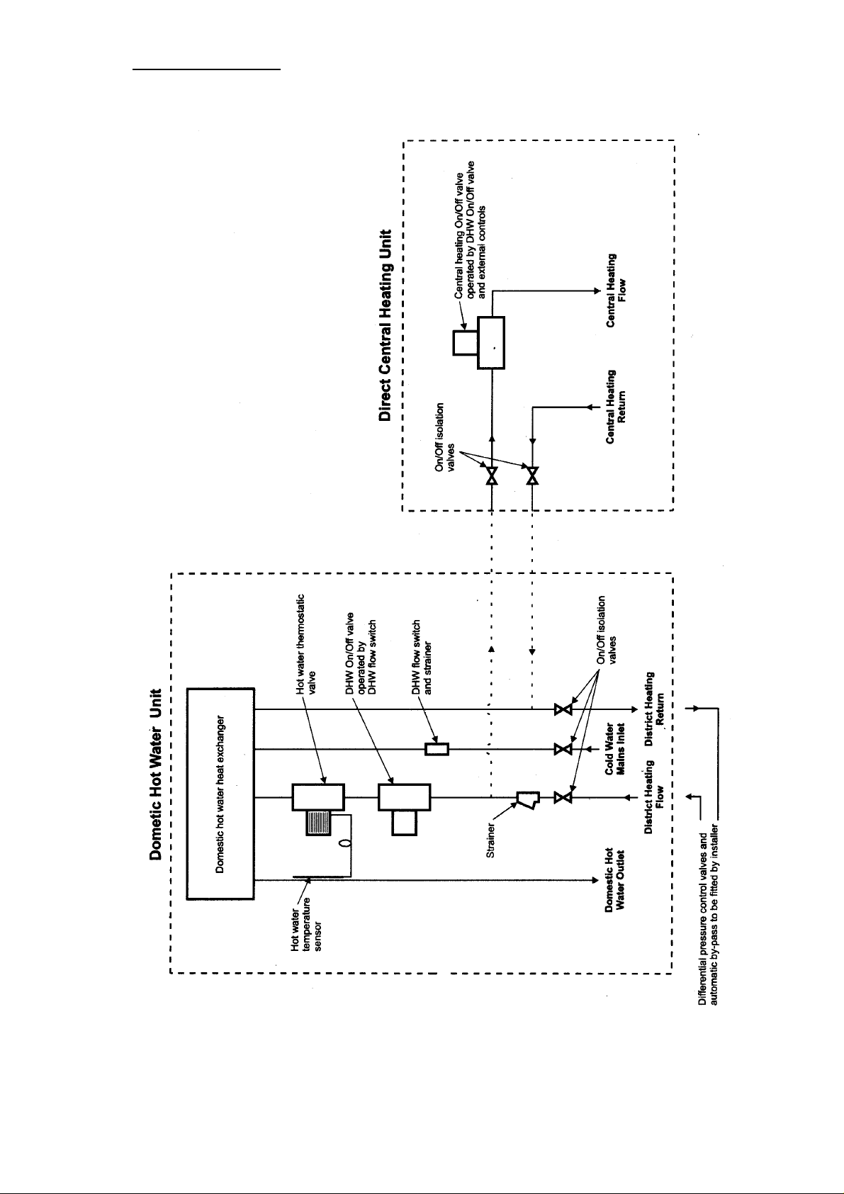
2.6 Schematic Diagram
5
Page 6

3/ OPERATION
Domestic hot water is available continuously and always takes priority over central
heating. If a demand for hot water is required during a central heating period the
controls will automatically switch to the hot water mode until the demand is
satisfied. This interruption in the central heating is only when the demand for hot
water is present and should not be noticed by the User.
3.1 Domestic Hot Water mode
When a demand for hot water is sensed by the flow switch, the DHW valve is
opened via a relay and district heating water is circulated to the plate heat
exchanger thus heating the incoming mains water. The hot water is maintained at
the set temperature by the hot water thermostatic valve regulating the district
heating water flow to the heat exchanger. When the flow switch senses that hot
water is no longer required the DHW valve closes.
3.2 Direct Central Heating
If there is a call for heating from an external control the CH valve will open and
allow district heating water to circulate to the dwelling’s radiator circuit. When there
is no demand for heating the CH valve will close. If there is a demand for hot water
the CH valve will be closed and will not be allowed to open until the hot water
demand has been satisfied.
4/ INSTALLATION
4.1
DCH Box - CH valve, two 22mm isolation valves
Unpacking
(1) The contents of each box is as follows:-
DHW Box - Assembled unit panel mounted with heat exchanger,
flow switch, DHW valve, hot water controller, control box
and pipework
Thermostat and sensor
Thermostat sensor kit, screws and wall plugs
Two 22mm isolation valves, strainer, 15mm Isolation valve
(2) Unpack and remove loose items
6
Page 7

4.2 Unit Location
(1) The unit is not suitable for external installation. It must be installed vertically on
a flat vertical wall which is capable of supporting its weight.
(2) Decide upon the position of the unit taking into consideration the clearances
required (Refer Sect 2.5)
(3) Refer to diagram below for the layout and location of the two units:
7
Page 8

4.3 Fit the DHW Unit
(1) Drill four fixing holes (5mm dia) through the back panel of the unit to accept
the No. 8 screws supplied.
(2) Hold the unit on the wall in the required position ensuring it is level and mark the
position of the fixing holes. Then drill the fixing holes (6mm dia) in the wall to
accept the No.8 wall plugs.
(3) Using the screws supplied secure the unit to the wall.
4.4 Fit the Ther mostat and Sensor (Refer Diagram 4.2.3)
(1) Unscrew the plastic cap on the hot water control valve body and remove.
(2) Locate and secure the thermostat onto the valve body by tightening the loose
nut by hand onto the thread of the body.
(3) With care unwind the capillary tube and position the sensor onto the location
provided on the outlet pipe from the heat exchanger.
(4) Secure the sensor in position using the tape supplied. Then locate the
insulation supplied around the sensor and secure with the two straps provided.
4.5 Connect the Pipework (Refer Diagram 4.2.3)
(1) Thoroughly flush out ALL the
pipework.
(2) Connect the 15mm isolating valve to the cold inlet pipe of the unit and then
connect the domestic hot water pipework.
(3) Using a ‘T’ connection, connect the central heating pipework to the DH flow and
return of the DHW unit and fit the CH valve and isolating valves in the positions
shown in the diagram 2.6.
Note:
Ensure the CH valve is located within 600mm of the DHW unit. This will
allow it’s cable to be directly connected into the unit’s control box .
(4) Connect the 22mm strainer supplied to the DH flow pipe and then connect the
two isolation valves to the DH flow and return pipes.
Note:
Ensure the strainer is always fitted after the valves. This will allow
isolation for cleaning of the filter (Refer diagram 2.6)
4.6 Connect the CH Valve Electrical Cable (Refer Sect 2.4)
(1) Gain access to the DHW terminal block by releasing the 4 screws securing
the control box cover.
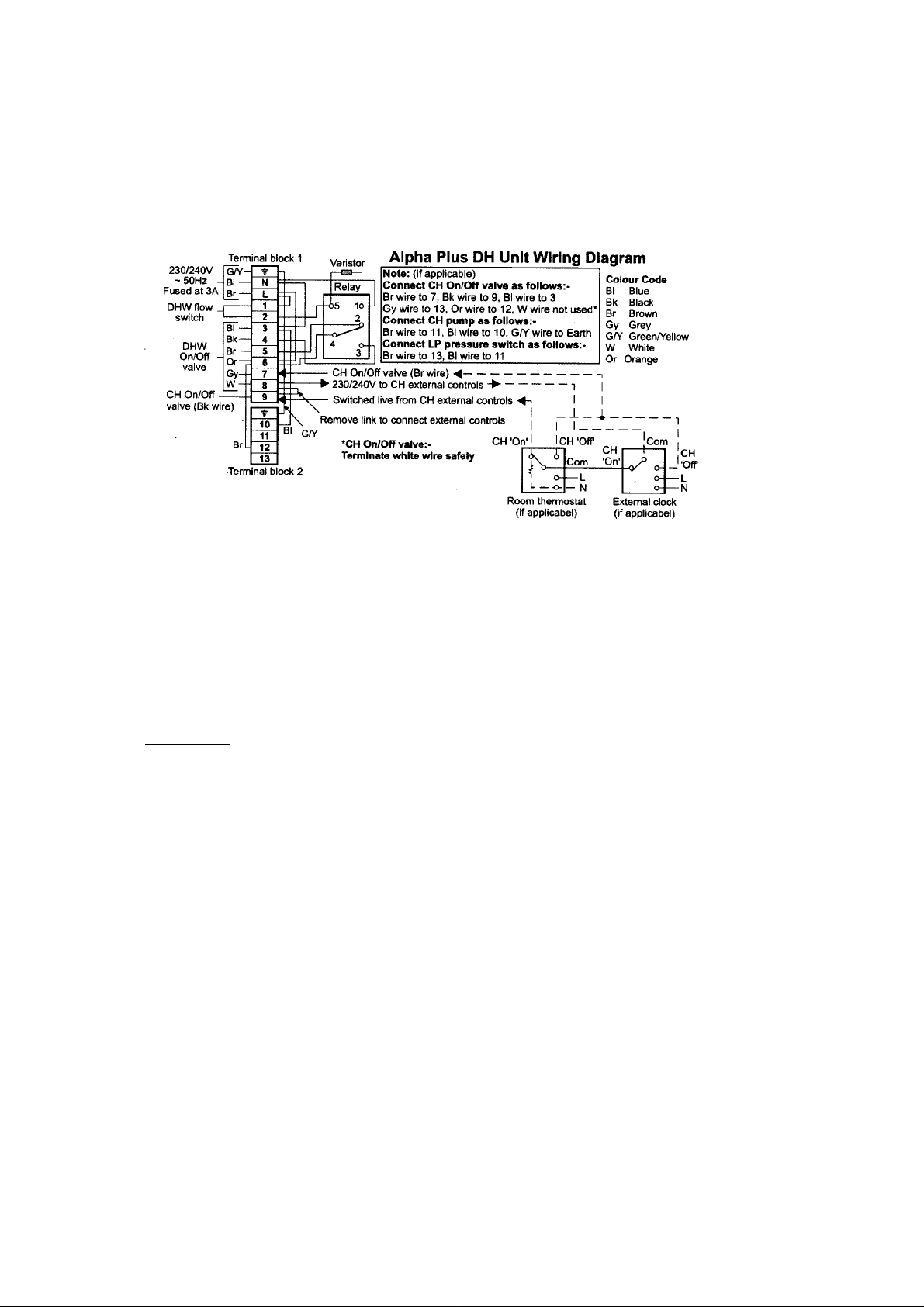
(2) Pass the CH valve’s electrical cable through a cable clamp and connect the
wires as follows (refer to diagram 2.4);
Brown to terminal 7, Black to terminal 9, Blue to terminal 3, Grey to terminal 13,
Orange to terminal 12, White is not used, therefore terminate safely.
(3) Tighten the cable clamp by hand until the cable is secured.
8
Page 9

4.7 Connect the Electrical Supply (Refer Sect 2.4)
The Unit requires a 230/240V ~ 50Hz mains supply, fused at 3A
The Unit must be earthed.
There must be only one common isolator, providing complete electrical isolation, for
the Unit and any external controls.
Using PVC insulated cable not less than 0.75mm
the Unit should be connected to a fused three pin plug and uns witched shuttered
socket outlet (both complying with BS1363), or a fused double pole switch with a
contact separation of at least 3mm in both poles.
Wiring external to the Unit must be in accordance with the current IEE Wiring
Regulations (BS7671).
NOTE:
The procedure is as follows:
(1) Gain access to the terminal block as in 4.6.1.
(2) Pass the mains supply cable through the cable clamp and connect as follows:-
(3) If an external control i.e. room thermostat or external clock is to be fitted,
(4) Ensure there is sufficient free cable to allow the control box cover to be
(5) Carry out electrical system checks – short circuit, polarity, earth continuity
If external controls are fitted, they MUST be suitable for 230/240V
switching and MUST be single pole, 2 way / Changeover switching
Brown to L, Blue to N and Green/Yellow to earth. Ensure correct polarity.
Note:
Ensure that the length of the earth wire is such that if the supply cable
is pulled out of its clamp the live and neutral wires become taut before
the earth wire.
remove the link between terminals 8 and 9. Pass the cable through the cable
clamp and connect to terminals 8 & 9 using terminal 9 as switched live.
removed giving easy access to the main terminal block, then tighten the cable
clamps by hand.
and resistance to earth with a suitable multimeter.
² (24 x 0.2mm) to BS6500 Table 16,
9
Page 10

(6) Ensure terminal block 2 is correctly located into the control box as shown below.
(7) Replace the control box cover and secure with the 4 screws previously
removed.
10
Page 11

5/ COMMISSIONING
(1) Fill the DHW pipework.
Open the cold mains inlet valve. Turn on all the hot water taps and allow water
to flow until there is no air present. Turn off the taps and check for water
soundness, rectifying if necessary.
(2) Fill the DH circuit pipework.
Open the DH flow and return isolation valves.
Manually open the DHW valve to allow water to flow by pushing the white lev er
down to midway and in on the valve’s actuator. This will hold the valve in the
open position. Check for water soundness, rectifying if necessary.
(3) Fill the Direct Central Heating system.
Open the CH flow and return isolation valves and allow DH water to flow into the
system. Vent each radiator etc to remove any air and check for water
soundness, rectifying if necessary.
(4) Turn on the electrical supply.
Open a hot water tap and check that the DHW valve opens, the CH valv e closes
and hot water is supplied. Set the outlet temperature as required by adjusting
the thermostat’s knob (Setting 9 gives approximately 55 to 60’C). Turn off the
tap and check the DHW valve closes and the CH valve opens.
6/ SERVICING and COMPONENT REPLACEMENT
Each component is easily removable for replacement or cleaning without needing
to remove other components
11
Page 12

7/ SHORT PARTS LIST
Description Alpha Pt. No.
DHW Heat Exchanger 1.020259
DHW Flow Switch 1.015142
Pipe 1 – Mains Inlet/Flow Sw 1.019921
Pipe 2 – Flow Sw/HE 1.019922
Pipe 3 – DHW Outlet 1.019923
Pipe 4 – DH Flow 1.019924
Pipe 6 – DH Return 1.020254
Pipe 7 – 22 x 60mm 6.3000144
Elect Plug Flow Switch 6.3000111
Relay (Control box) 6.3000112
Control Box 6.3000110
DHW/CH Valve 6.3000120
Thermostat Body 6.3000131
Thermostat Head 6.3000130
15mm Isolation Valve 6.3000141
22mm Isolation Valve 6.3000142
22mm Strainer 6.3000143
Thermostat & Fixing Kit 6.3000136
DHW Flow Regulator 10L 1.016595
12
Page 13

13
Page 14

These instructions have been carefully prepared but we reserve the right to alter the
specification at any time in the interest of product improvement. Alpha Therm Ltd 2005
Part no 6.3000160
04/05
14
 Loading...