

Page 1
User's
Instructions
Eco
Wall Mounted, Fan Assisted, Room Sealed,
Gas Fired, High Efficiency Condensing Combination Boiler
Nepicar House, London Road,
Wrotham Heath, Sevenoaks,
Kent TN15 7RS
For Technical help or for Service call ...
ALPHA HELPLINE Tel: 0844 871 8764
website: www.alpha-innovation.co.uk
Alpha Eco G.C. No. 47 532 59
For use with Natural Gas only
Leave these instructions with the User
0051
Page 2
2
Eco
The Eco high efficiency condensing boiler incorporates the latest technology in boiler design. With improved burner efficiency
and reduced electrical consumption together with high quality and reliability.
The boiler output will automatically adjust according to the requirements of the system.
The Eco is designed to work with most central heating controls however we recommend the Alpha Comfort standard controls
or the enhanced Alpha Climatic boiler energy manager further improving the system efficiency by varying the system
temperature depending on the room temperature and heat losses.
In addition the Eco features optional connections for an outside sensor to enable the boilers built in weather compensation
feature.
The boilers will provide central heating when required during the on times as set according to the controls fitted. Hot water
will always take priority over the central heating whenever a hot tap is opened.
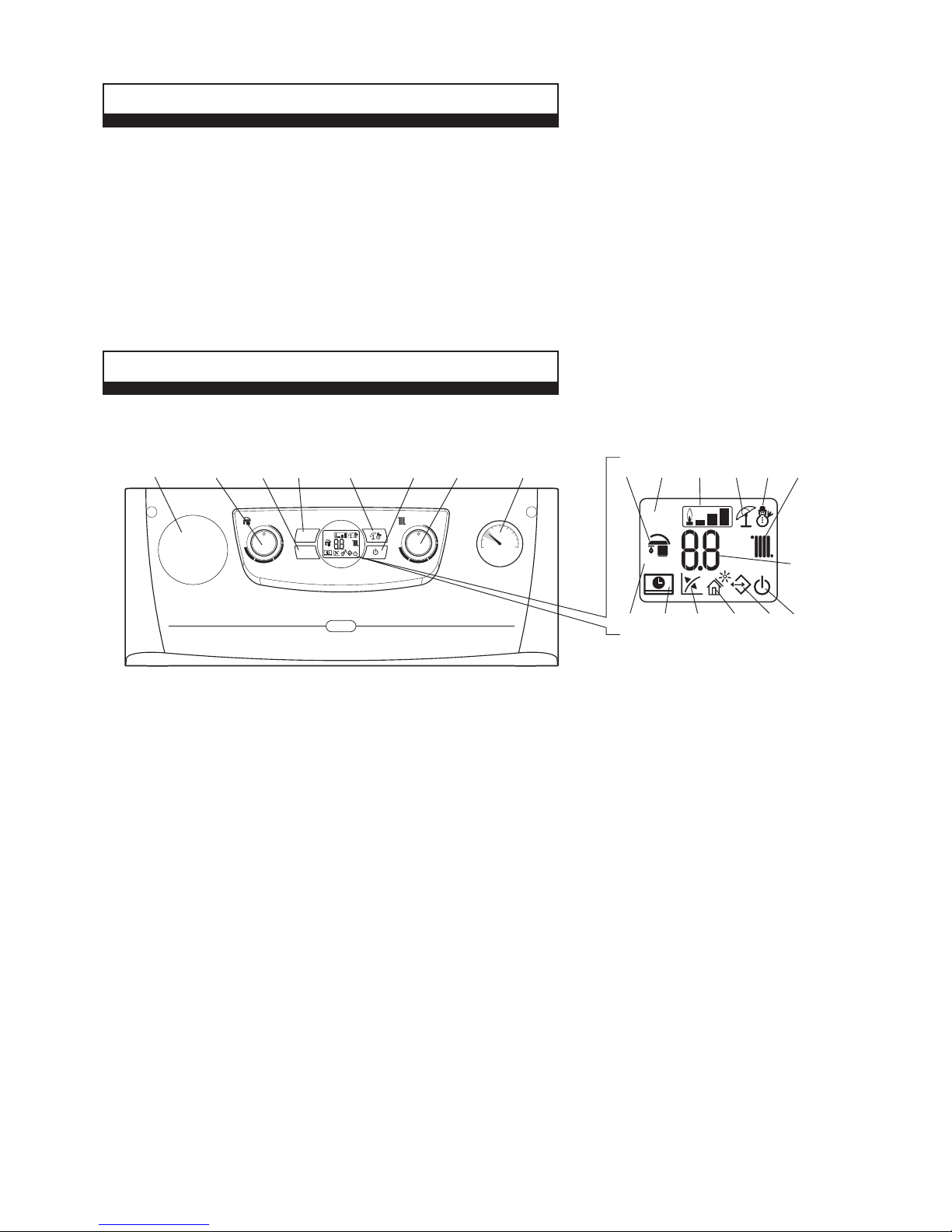
Fig. 1
2 OPERATING THE BOILER
1 INTRODUCTION
Make sure the heating system is filled and the needle on the pressure gauge (item 7 in Fig. 1) is in the green band. If
incorrect refer to Section 5.
Switch the boiler on at the mains supply socket switch. The boiler will automatically go through a system purging operation
for 8 minutes; this is indicated by a count down on the display starting from 96. During this operation the pump will turn on
and off to help remove any air that may be trapped in the heating system. If the boiler has already been commissioned by the
installer then this operation can be terminated by pressing the reset button (item 3 in Fig. 1).
Note: It is important to allow this purging operation to function when the boiler has been initially installed to remove all the air
from the system.
After this purging operation the boiler will be in 'Standby' or 'On' mode.
By pressing the On-Off button (item 1 in Fig. 1) the Standby or On mode can be selected, or press and hold the On-Off
button for eight seconds to turn the boiler off.
Standby - In this mode the boiler will not provide hot water or central heating, but frost protection and pump circulation
features are still active.
Off - In this mode there is electrical power to the boiler but the boiler will not function in any condition.
The boiler controls are located on the control panel.
Please read these instructions carefully before operating your boiler.
1 On-Off/Standby button
2 Summer/Winter button
3 Reset button
4 Information button
5 Domestic hot water temperature
selector switch
6 Central heating water temperature
selector switch
7 Heating system pressure gauge
8 DHW mode active
9 Boiler locked does not require reset via
“RESET” button
10 Flame present symbol and relative
power scale
11 Operating in summer mode
12 Operating in winter mode
13 Central heating mode active
14 Temperature indicator, boiler info and
error codes
15 Boiler in Stand-by mode
16 Presence of external connected devices
17 Solar function active
18 Functioning with external temperature
probe active (optional)
19 Boiler connected to remote control
(optional)
20 Not used on this model
21 Optional boiler controls (if fitted)
RESET
BOOST
bar
°C
x100rpm
RESET
INFO
bar
0
4
3
2
2.5
3.5
1.5
0.5
1
CORRECT PRESSURE
WHEN COLD
12
3
4
5 6
721
RESET
BOOST
bar
°C
x100rpm
8 9 10
11 12
13
14
151617181920
Eco
Page 3
3
Eco
The temperature of the hot water to the taps can be adjusted by turning the hot water selector switch (item 5 in Fig. 1) to the
required value shown on the display in °C.
When a tap is opened the display will indicate the temperature of water in the boiler heating the tap water and not the actual
water temperature to the tap.
The temperature of the central heating water can be adjusted by turning the central heating selector switch (item 6 in Fig. 1).
When the heating is on the temperature of the water leaving the boiler to the radiators will be displayed.
If an external weather compensation probe is fitted, indicated by the
symbol (item 18 in Fig. 1) in the display, it will
automatically vary the temperature of the water in the radiators and on mild day the radiators will not feel as hot as on a cold
day, this is normal and not a fault with the boiler or heating circuit. The room temperature will still be maintained as set by the
room thermostat.
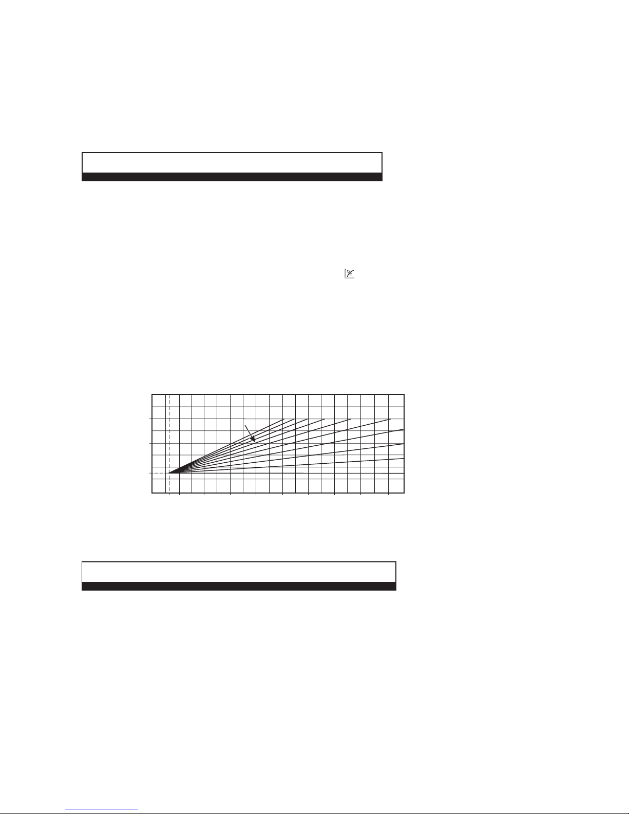
When an external weather probe is fitted, the central heating selector switch (item 6 in Fig. 1) will no longer adjust the flow
temperature in °C, instead the display will show a scale of 1 to 9. Each number corresponds to a line on the graph in Fig 2
i.e. line 6 will give a flow temperature of 60°C when the external temperature is 10°C.
Note: This is the temperature of the water supplied to the radiators and not the desired room temperature. The time and
temperature will still be maintained according to the setting of the room thermostat.
3 HEATING AND HOT WATER TEMPERATURE
On - In this mode the boiler can be switched between 'Summer' or 'Winter' settings by pressing the Summer/Winter button
(item 2 in Fig. 1).
Summer setting - The boiler will only provide hot water when a tap is turned on and the central heating will not activate even
if requested by external controls (frost protection and pump cycle are still active).
Winter setting - The boiler will operate in both heating and hot water. The heating will activate depending on the time and
temperature from any heating controls fitted. Hot water will always take priority over heating when a hot outlet tap is opened.
Fig. 2 - External weather compensation probe fitted
Flow temperature (°C)
External temperature (°C)
27 15
5
-510 0 -10 -1520
25 (25)
60 (40)
85 (50)
Flow temperature in brackets
ie. 25 to 50°C range when boiler
is used with a low temperature
system such as under floor heating
Setting 1 to 9 as selected using
the central heating selector switch
9 8
7
6
5
4
3
2
1
0
4 FILL AND PRESSURISE THE SYSTEM
Your boiler should have a filling loop fitted by the installer located in the pipework below the boiler.
Do not attempt to fill or pressurise the system while the system is hot - wait for it to cool.
The filling loop on the underside or underneath the boiler will have two tap connections at either end of the filling loop.
These taps should normally be in the closed position 90° to the tap housing.
To fill or pressurise the system open one tap fully by turning it 90° anticlockwise in line with the tap housing. The second tap
should be opened a quarter of a turn and the water will start to refill the system (water should be heard filling the system).
You should see the pressure gauge (item 7 in Fig. 1) rise back up into the green area on the pressure gauge between 1 bar
and 1.5 bar pressure.
Once the pressure gauge is in the green area turn the taps back to the off position and the water will stop filling the system.
If you happen to fill the system too much and the pressure gauge is over the green area, just bleed water from a radiator until
the pressure on the gauge goes down into the green area.
Page 4

4
Eco
By pressing the info button (item 4 in Fig. 1) the information menu is accessed this will then show the information according
to the table below.
6 FROST PROTECTION
7 CONDENSATE DRAINAGE
High efficiency (condensing) boilers remove more useful heat from the combustion gases, resulting in additional water vapour
which is collected within the boiler (as condensate) and run to a suitable drainage point via the condensate drainage pipe.
If the condensate drain pipe runs outside it should be fitted with increased diameter pipe and be suitably lagged to reduce
the risk from freezing.
In situations where there are likely to be extremes of temperature or wind-chill the use of a proprietary trace-heating system
for external condensate drainage pipework, incorporating an external frost thermostat, should be considered.
5 INFORMATION MENU
The boiler has a built in frost protection function to protect the boiler (only) from freezing. If water within the boiler falls below
4°C the boiler will fire in heating mode and raise the temperature of the heating water (in the boiler only) to 30°C.
For this function to be active the gas and electricity supplies to the boiler must be turned on and the boiler be in either
'Standby' or 'On' mode.
Further protection for the mains water supply and heating circuit must be provided separately.
If Alpha external controls are fitted, a frost protection setting is incorporated into the room thermostat activating the central
heating when the temperature falls below 5°C.
Info Menu
(d - prefix)
d0
d1
d2
d3
d4
d5
d6
d7
d8
d9
Information
FlowSmart cylinder temperature adjustment (45 - 78°C)
Flame signal
Central heating water temperature leaving the boiler
Domestic hot water temperature leaving the boiler
Central heating set point temperature
Domestic hot water set point temperature
External weather compensation probe temperature (value flashes if negative)
Mains inlet temperature or FlowSmart cylinder temperature (if sensor fitted)
Not used
Fault history - by rotating the CH knob (item 6 in Fig. 1) in this menu the last five faults will be displayed
Units
Shown
°C
mA x 10 (approx)
°C
°C
°C
°C
°C
°C
Error code
Page 5

5
Eco
The Eco boilers are fitted with a fault code display feature.
If a fault occurs a fault code will be displayed in the LCD display screen (item 14 in Fig. 1), indicated with an alternating
flashing E followed by the fault code. A list of fault codes are given in the table below.
In the event of a fault occurring firstly check that the gas and electricity supplies are on and that any external controls fitted
are set and working correctly.
Press the reset button (item 3 in Fig. 1) on the control panel to restart the boiler if the fault occurs again, make a note of the
fault code and contact your installer or Alpha technical Helpline for further advice.
8 OPERATIONAL FAULTS
Error
code
Fault Fault description Possible causes
Gas supply
Check pressure tubes
Ignition electrode gap
Flame sensor electrode gap
Ignition generator or lead
Flame sensor electrode lead
Gas valve setting
Gas valve
PCB
Pump or flow problem
Blocked heat exchanger
Air in heat exchanger
Overheat thermostat
Thermal fuse (if open circuit then replace
primary heat exchanger)
Blocked or restricted primary flow
Heat exchanger air flow blocked
Flue restriction
Flue sensor fault
Gas valve lead connection fault
Faulty gas valve
Faulty PCB
Flow sensor wire connections
Flow sensor faulty
DHW sensor wiring connection
DHW sensor faulty
Refer to fault history codes (INFO menu d9)
Check expansion vessel pressure (1 bar)
Leak in system
Expansion relief valve operated
Primary pressure switch
Cylinder sensor wiring connections
Cylinder sensor faulty
Check internal wiring connections to PCB
Combination boiler DHW sensor X4
System boiler link X14
Refer to wiring diagram
Check fan wiring connections
Fan fault
PCB fault
Flame not detected during ignition sequence
Overheat thermostat or thermal fuse has operated
Flue thermostat intervention (flue temperature
over 113°C)
Gas valve wiring circuit fault detected
Incorrect flow sensor resistance value
DHW sensor resistance value is incorrect
Maximum number of resets reached (5)
Primary pressure switch has operated
Incorrect cylinder sensor resistance
Incorrect wiring configuration detected
Fan wiring fault or fan faulty
Ignition failure
Overheat boiler lock
out
High flue thermostat
temperature
Gas valve electrical
connection fault
Heating flow sensor
fault
DHW sensor fault
Maximum number of
resets
Primary system
pressure low
Cylinder sensor fault
(FlowSmart only)
Internal wiring error
Fan fault
01
02
03
04
05
06
08
10
12
15
16
Page 6

6
Eco
Error
code
Fault Fault description Possible causes
Check flame sensing electrode and lead
PCB fault
Check for jammed control panel buttons
Check for jammed PCB buttons
Air in heat exchanger
Blocked or restricted primary flow
Heat exchanger air flow blocked
Flue restriction
Flue sensor fault
Pump fault
Boiler or heating circuit valve closed
Blocked or restricted primary flow
Air in heat exchanger
Boiler or heating circuit valve closed
Pump fault
Primary flow sensor fault
Check sensor wiring connection
Flue sensor faulty
Remote control or receiver connection wiring
Remote control or receiver
Check mains power supply
Check flame sensing electrode and lead
Check for flue gas recirculation
Check/adjust the gas valve settings
Check/adjust the fan speed settings
Check gas supply/working pressure
Check flame sensing electrode and lead
Check for flue gas recirculation
Check/adjust the gas valve settings
Check/adjust the fan speed settings
Check external control (room thermostat)
requests
Rapid on/off hot tap requests
Check external sensor and cable are not
damaged or wet
Check continuity of external sensor and circuit
Check connection at X19 on PCB and sensor
connecting block
Air in heat exchanger
Restricted primary flow
Heat exchanger air flow blocked
Flue restriction
Flue sensor fault
Pump fault
Batteries require replacing
Distance between boiler and climatic control
too great
Interference
Object blocking signal (metallic)
False flame detection
Flame detected but gas valve is not open
Control panel button stuck in the on position
Rapid temperature rise of flue sensor
Rapid temperature rise of primary sensor
Flue sensor resistance out of range
Loss of connection between the boiler and
Alpha Climatic control unit
Insufficient supply voltage to operate boiler
Flame detected but signal is lost. Ignition
reattempts after fan purge
Repeated loss of flame signal during operation
(shown as E38 in the fault code history in the
INFO menu)
The boiler has attempted to fire repeatedly for
the maximum time limit
No continuity of external sensor circuit
Flue thermostat has sensed high flue gas
temperature (110°C) and reduced the burner
output to prevent damage. If the temperature
continues to rise the boiler will lock out and E03
will be displayed
Error between the communication of the
Climatic transmitter and boiler receiver
Flame sensing fault
Control panel button
fault
Overheat lock out
Insufficient primary
flow
Flue sensor fault
Loss of
communication with
external control
(Alpha Climatic)
Low supply voltage
Loss of flame
rectification
Loss of flame
rectification
Safety lock out
External sensor
intervention
Reduced burner
output
Climatic RF
communication fault
20
24
25
27
29
31
37
38
43
44
46
47
51
Page 7

7
Eco
10 GAS SAFETY REGULATIONS
1. BOILER LOCATION
Always ensure the following clearances are available around the casing of the boiler:-
Top: (horizontal flue) 235 mm, Top: (vertical flue) 150 mm, Bottom: 150 mm, Each side: 5 mm, Front: 450 mm
Do not store any other articles in a cupboard containing the boiler and never place any clothing or combustible material on or
near the boiler or flue pipe.
2. FLUE TERMINAL
The terminal on the outside wall must not be allowed to be obstructed. If it is damaged, in any way, turn the boiler off and
contact your Service Engineer.
Note: The Eco boilers are high efficiency condensing boilers and when operating vapour will be emitted from the terminal.
This is safe and quite normal.
3. MAINS FAILURE
In the event of an electrical supply failure the boiler will not operate. When the supply is restored, the boiler will return to
normal operation. Remember to reset any controls, if fitted, when the supply is restored.
If the mains water supply fails, there will be no hot water from the taps. The boiler will continue to provide central heating.
4. ADDITIONAL BATHROOM FITTINGS
Any equipment such as mixing valves, showers, bidets etc. must be designed to operate at mains water pressure. Contact
your plumbing merchant or installer for advice when considering purchasing such items.
5. CLEANING
Use only a damp cloth and mild detergent to clean the boiler outer casing. Do not use abrasive cleaners.
6. SERVICING
To maintain efficient and safe operation of your boiler, routine annual servicing is essential.
For advice on servicing contact:- The Alpha Helpline: 0844 871 8764.
7. GAS LEAK
If a fault or gas leak is suspected, turn off the gas supply. Do not touch any electrical switches, do not smoke and extinguish
all naked flames. Contact your local Gas Region immediately on 0800 111 999.
8. ELECTRICAL SUPPLY
The boiler requires a 230/240 V ~ 50 Hz supply, fused at 3 A if a 13 A 3-pin plug is used or a 5 A fuse if any other type of
plug is used.
To connect a plug:-
The colour of the wires in the mains lead of the boiler may not correspond with the coloured markings identifying the
terminals in your plug. In this case proceed as follows:-
The wire coloured green and yellow must be connected to the terminal in the plug that is marked with the letter E, or by the
earth symbol
, or coloured green or green and yellow.
The blue wire must be connected to the terminal which is marked with either the letter N or coloured black.
The brown wire must be connected to the terminal which is marked with the letter L or coloured red.
THE APPLIANCE MUST BE EARTHED.
9 IMPORTANT NOTES
Current Gas Safety (Installation and Use) Regulations:-
It is the law that all gas appliances are installed and serviced by a competent person, i.e. Gas Safe registered personnel.
Failure to install or service appliances correctly could lead to prosecution. It is in your interest and that of safety to ensure
compliance with the law. The manufacturer's instructions must not be taken in any way as over-riding statutory obligations.
The Benchmark Checklist must be fully completed by the installer on installation of the boiler. The Benchmark Checklist is
shown in back of the Installation and Servicing instructions. All Gas Safe registered installers carry a Gas Safe ID card and
have a registration number. Both should be recorded in the Checklist. You can check your installer is Gas Safe registered by
calling Gas Safe on 0800 408 5500.
Page 8

Instructions compiled and designed by Publications 2000 - Tel: 01670 356211 09/13/D328
These instructions have been carefully prepared but we reserve the right to
alter the specification at any time in the interest of product improvement.
© Alpha Therm Limited 2013.
Alpha Therm Limited.
Nepicar House, London Road, Wrotham Heath,
Sevenoaks, Kent TN15 7RS
Tel: 0844 871 8764
email: info@alpha-innovation.co.uk
website: www.alpha-innovation.co.uk
Part No. 1.033693 Rev 15.037883/000
11 OPTIONAL BOILER CONTROLS (if fitted)
There is a range of controls available from Alpha to operate your boiler. In addition to the items listed below the Eco boilers
are compatible with most controls available on the market. However to get the most comfort and efficiency from your boiler
we recommend the Alpha Climatic controls with enhanced remote boiler functions and efficiency control.
Please refer to the instructions provided with the controls for further information on their setting and use.
Available Alpha controls:
24hr mechanical heating clock (boiler mounted) ........................................................................................ Part No. 6.1000201
7 day digital heating clock (boiler mounted) ...............................................................................................Part No. 6.1000210
Alpha Comfort 7 day wireless programmable room thermostat (boiler mounted receiver) .........................Part No. 3.022141
Alpha Climatic wired programmable boiler energy manager (boiler mounted) ........................................... Part No. 3.022144
Alpha Climatic wireless programmable boiler energy manager (boiler mounted receiver) .........................Part No. 3.022143
External weather compensation probe ....................................................................................................... Part No. 3.022383
Optional boiler controlled condensate trace heating kit ..............................................................................Part No. 6.5500000
 Loading...