

Page 1
AlphaNet™ DSM3 Series DOCSIS® Status Monitor
for the XM3 CableUPS
®
Installation and Quick Start Guide
The AlphaNet DSM3 Series (DSM3, DSM3x, DPM models) Embedded DOCSIS Communications Module allows monitoring of Alpha power
supplies through existing cable network infrastructure. Advanced networking services provide quick reporting and access to critical powering
information.
DSM3 Series Communications Modules utilize Simple Network Management Protocol (SNMP) and Management Information Bases (MIBs) to
provide network status monitoring and diagnostics. A Web interface enables authorized personnel direct local and remote access to advanced
diagnostics using a common Web browser. No proprietary cables or software are required.
The Communications Modules can be installed and congured for operation in the XM3-HP CableUPS® Power Supply. The major features of
the DSM3x are shown below; the DSM3 and the DPM models are shown on the following pages.
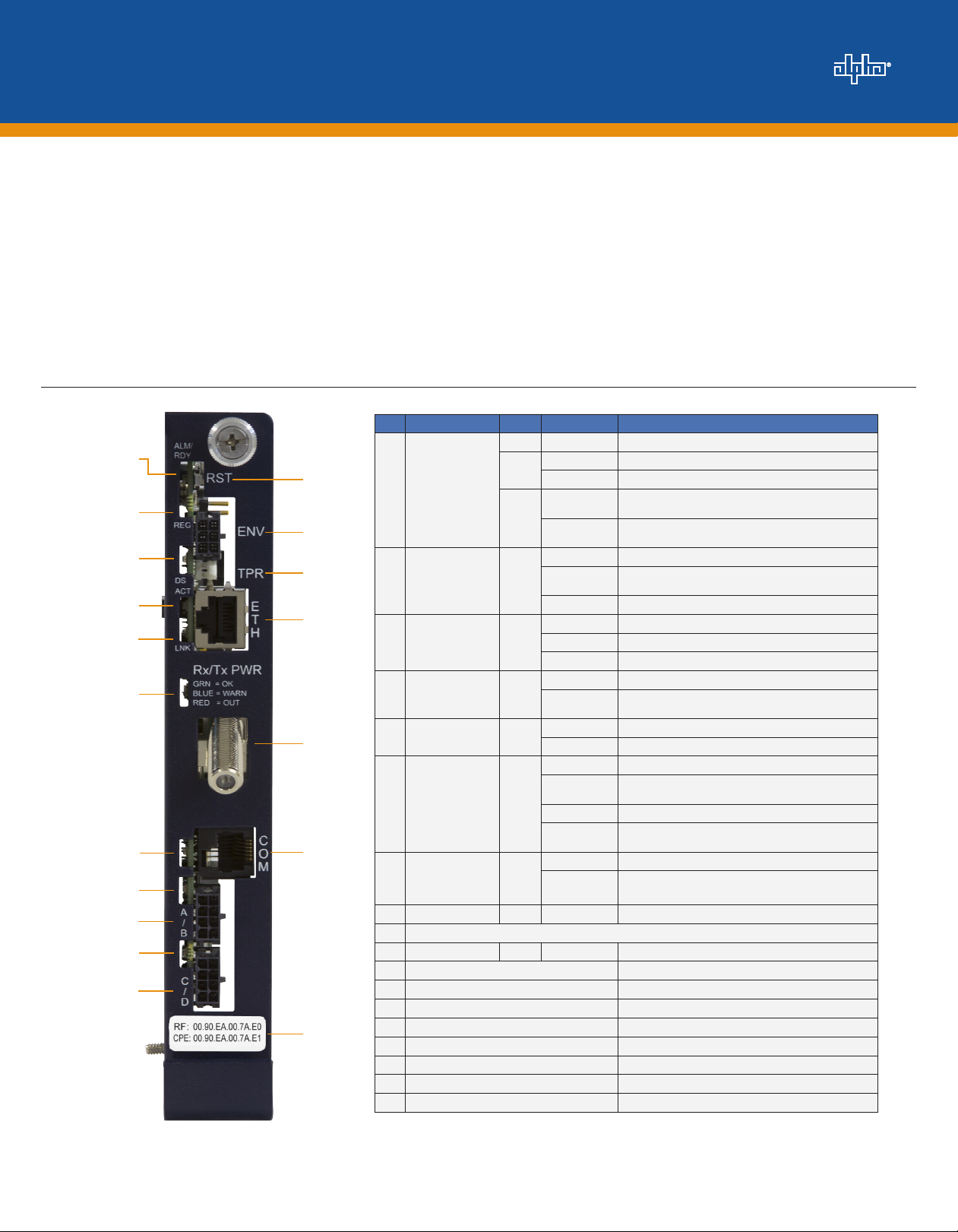
DSM3x DOCSIS Communications Module
Item LED or Connector Status Behavior Indication
N/A OFF No power or malfunctioning DSM3 Series
10
11
1
12
ALM/RDY: Alarm and
1
Ready
2
13
3
14
2
REG: Upstream
ranging and
registration lock
4
15
5
6
16
7
17
8
9
18
DS: Downstream
3
RF Carrier detection
and lock
ACT: CPE Activity
4
status
LNK: CPE Link
5
status
RF Rx/Tx Power
6
Level Indicator
COM: AlphaBus
7
communications
8 BAT A/B GRN ON/OFF ON (steady) if battery string(s) connected correctly
9 BAT A/B Connector
10 BAT C/D GRN ON/OFF ON (steady) if battery string(s) connected correctly
11 BAT C/D Connector
12 RST: Reset Buttton
13 ENV: Environmental Control Connector
14 TPR: Tamper Switch Connector
15 ETH: Ethernet Connector
16 RF Connector
17 COM: AlphaBus Communications Connector
18 CM, CPE MAC Address Label
ON Reset of the DSM3 Series is in process
GRN
Steady Blinking Normal operation
Blinking more
OFF than ON
RED
Blinking more
ON than OFF
OFF No power, upstream frequency undetermined
Blinking
GRN
ON CMTS registration completed
OFF No power / downstream carrier
GRN
Blinking Power on, downstream carrier frequency searching
ON Downstream carrier lock
OFF No Ethernet communications activity
GRN
Blinking
OFF No Ethernet link
GRN
ON Link on Ethernet Craft port
OFF No RF detected
Blue
TRI
Green Rx/Tx RF Power level within tolerance
Red
OFF No AlphaBus Communications
GRN
Blinking Momentary ashes - AlphaBus Port communications active
Minor Alarm
Major Alarm
Power on, downstream locked, upstream frequency ranging,
DHCP request in progress
Momentary ashes during CPE communications via the
Ethernet craft port
Rx/Tx Power at a warning level as set within the SCTE-HMS
Property Table
Rx/Tx Power at an alert level as set within the SCTE-HMS
Property Table
Fig. 1, DSM3x Communications Module Front Panel Indicators and Connectors
1746-114-B5-001 Rev. B (04/2013)
Page 2
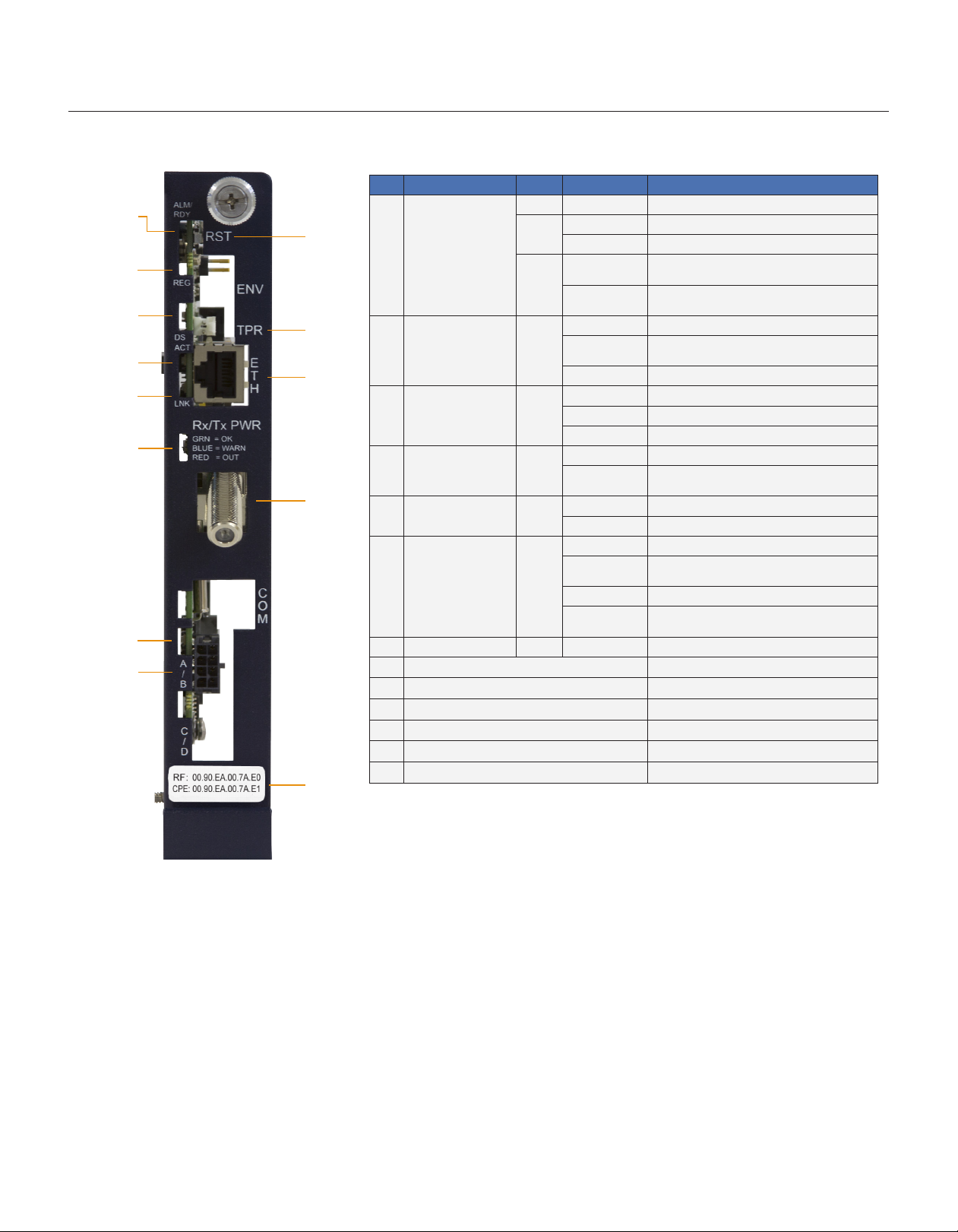
DSM3 DOCSIS Communications Module
Item LED or Connector Status Behavior Indication
1
9
2
3
10
4
11
5
6
12
7
8
13
ALM/RDY: Alarm and
1
Ready
REG: Upstream ranging
2
and registration lock
DS: Downstream RF
3
Carrier detection and lock
4 ACT: CPE Activity status GRN
5 LNK: CPE Link status GRN
RF Rx/Tx Power Level
6
Indicator
7 BAT A/B GRN ON/OFF ON (steady) if battery string(s) connected correctly
8 BAT A/B Connector
9 RST: Reset Buttton
10 TPR: Tamper Switch Connector
11 ETH: Ethernet Connector
12 RF Connector
13 CM, CPE MAC Address Label
N/A OFF No power or malfunctioning transponder
GRN
RED
GRN
GRN
TRI
ON Transponder reset in process
Steady Blinking Normal operation
Blinking more OFF
than ON
Blinking more ON
than OFF
OFF No power, upstream frequency undetermined
BLINKING
ON CMTS registration completed
OFF No power / downstream carrier
BLINKING Power on, downstream carrier frequency searching
ON Downstream carrier lock
OFF No Ethernet communications activity
BLINKING
OFF No link
ON Link on Ethernet Craft port
OFF No RF detected
Blue
Green Rx/Tx RF Power level within tolerance
Red
Minor Alarm
Major Alarm
Power on, downstream locked, upstream frequency
ranging, DHCP request pending
Momentary ashes during CPE communications via the
Ethernet Craft port
Rx/Tx Power at a warning level as set within the SCTEHMS Property Table
Rx/Tx Power at an alert level as set within the SCTEHMS Property Table
Fig. 2, DSM3 Communications Module Front Panel Indicators and Connectors
2746-114-B5-001 Rev. B (04/2013)
Page 3
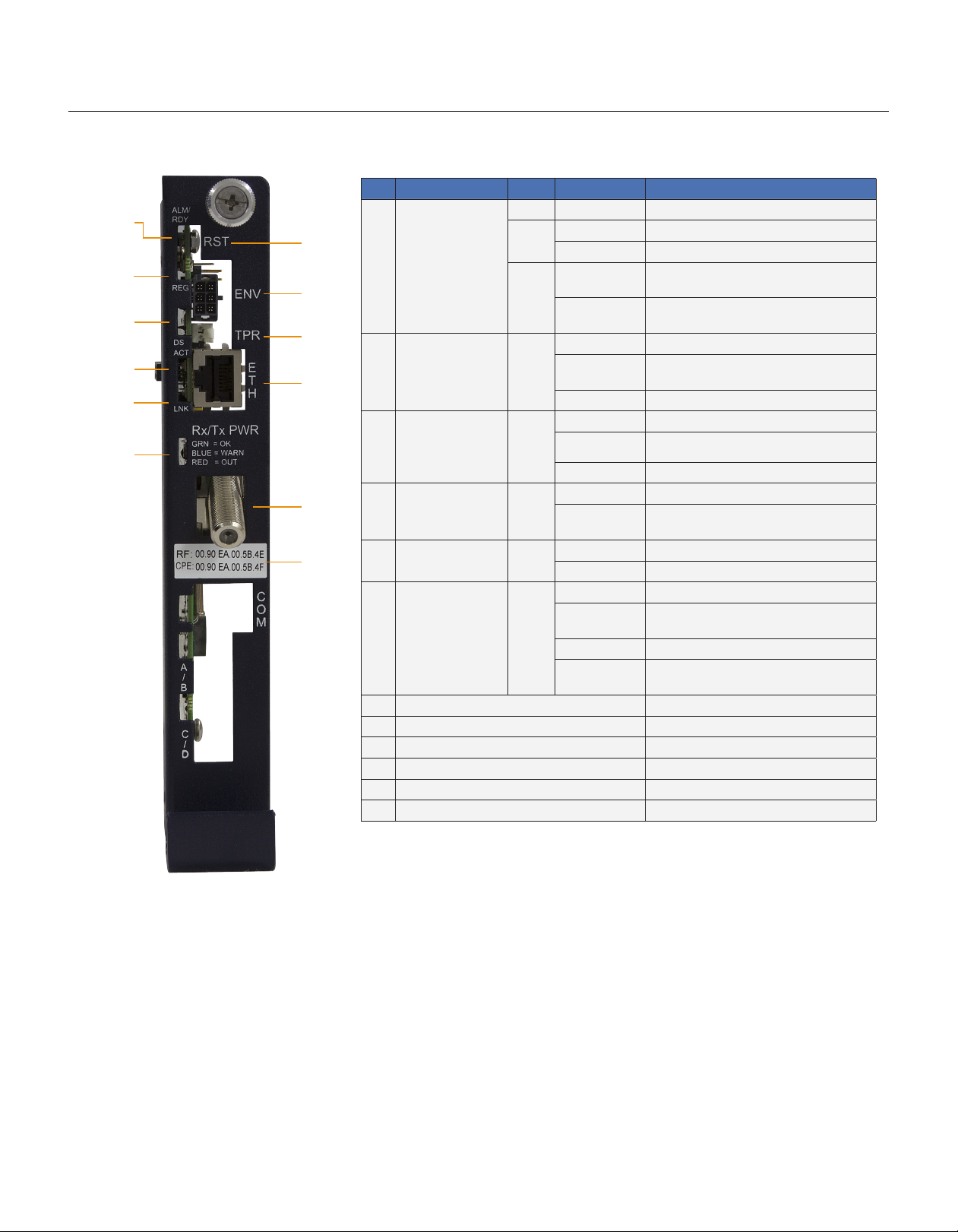
DPM DOCSIS Communications Module
Item LED or Connector Status Behavior Indication
1
7
ALM/RDY: Alarm and
1
2
8
3
9
4
10
5
6
11
12
Ready
REG: Upstream
2
ranging and
registration lock
DS: Downstream RF
3
Carrier detection and
lock.
ACT: CPE Activity
4
status
5 LNK: CPE Link status GRN
RF Rx/Tx Power Level
6
Indicator
7 RST: Reset Buttton
8 ENV: Environmental Control Connector
9 TPR: Tamper Switch Connector
10 ETH: Ethernet Connection
11 RF Connection
12 CM, CPE MAC Address Label
Note: The DPM requires the XM3 Smart AlphaGuard (SAG) option for individual battery voltage measurements.
N/A OFF No power or malfunctioning transponder
GRN
RED
GRN
GRN
GRN
TRI
ON Transponder reset in process
Steady Blinking Normal operation
Blinking more
OFF than ON
Blinking more ON
than OFF
OFF No power, upstream frequency undetermined
BLINKING
ON CMTS registration completed
OFF No power / downstream carrier
BLINKING
ON Downstream carrier lock
OFF No Ethernet communications activity
BLINKING
OFF No link
ON Link on Ethernet Craft port
OFF No RF detected
Blue
Green Rx/Tx RF Power level within tolerance
Red
Minor Alarm
Major Alarm
Power on, downstream locked, upstream
frequency ranging, DHCP request pending
Power on, downstream carrier frequency
searching
Momentary ashes during CPE communications
via the Ethernet Craft port
Rx/Tx Power at a warning level as set within the
SCTE-HMS Property Table
Rx/Tx Power at an alert level as set within the
SCTE-HMS Property Table
Fig. 3, DPM Communications Module Front Panel Indicators and Connectors
3746-114-B5-001 Rev. B (04/2013)
Page 4

Overview
CAUTION!
For units in service, backup battery power will not be available during this procedure.
DSM3 Series installation and setup is comprised of three basic steps:
1. Installation of the DSM3 Series into the power supply, making front panel connections and verifying operation.
2. Setting Options: the DSM3 Series is designed for out-of-the-box, "plug and play" operation. Non-default settings such as
SNMP trap destination addresses may be required for the Network Management System (NMS). SNMP trap addresses
can be set automatically via the DOCSIS conguration le's docsDevNmAccessTable per RFC 4639 (IPv4) or through
the SNMPv3 Notication settings (IPv6), while DSM3 Series proprietary options may be set through type 11 TLV entries.
The SCTE-HMS and Alpha MIBs may need to be compiled into a MIB browser before it can be used to monitor or set
transponder and power supply parameters. Refer to the DSM3 Series Technical Manual for details.
3. Conguring the Network: provisioning the DHCP Server with the transponder’s MAC address and assigning it a
DOCSIS conguration le.
These steps can be performed independently of one another. However, conguring the network prior to eld installation will
allow the installation to be veried while personnel are still on-site. Performing eld installation before network conguration
might result in additional eld service calls to correct mistakes.
Installation Procedure
Removing the Inverter Module:
1. Turn off the battery breaker.
CAUTION!
Service personnel must verify the Inverter Module battery breaker remains in the OFF position until instructed to
return unit to service.
2. Disconnect the battery input and temperature sensor cables from the Inverter Module and the tamper, RF and battery
sense cables from the communication module if one is currently installed.
3. Loosen the two thumbscrews on the XM3 Inverter Module.
4. Grasp the handle on the bottom right side of the Inverter Module. Pull rmly to release the module from the inverter
connector. Gently slide the module assembly straight out until the Inverter Module is accessible.
Fig. 3, XM3-HP with DSM3x Communications Module Installed
4746-114-B5-001 Rev. B (04/2013)
Page 5

Installation Procedure, continued
The following steps apply to both new installations or
removal/replacement of existing Communications Modules:
5. Line up the 18-pin connector on the Communications Module
(Fig. 5) with the 18-pin socket on the Inverter Module and connect
the two units together (Fig. 6).
6. Fasten the Communications Module to the Inverter Module
by tightening the two captive screws. (Fig. 4, items A) It is
recommended the screws be tightened alternately, a few turns
at a time so the Communications Module aligns in parallel to the
Inverter Module.
A
A
Fig. 4, Captive Screw Locations
Fig. 5, 18-pin Connector
Fig. 6, Connecting the Communications
Module to the Inverter Module
7. Reinstall the Inverter Module, tighten the two thumbscrews and
reconnect the front panel connections (tamper, temperature sensor,
battery harness, etc.).
8. Verify the recording of the cable modem MAC address (RF MAC) from the
front of the unit for network provisioning.
Fig. 7, Front Panel View of Completely Installed DSM3x in XM3-HP
5746-114-B5-001 Rev. B (04/2013)
Page 6

Installation Procedure, continued
9. Make Battery Sense Wire Kit connections (not required with Smart AlphaGuard). Refer to the battery diagrams provided
with the sense wire kit or reference the DSM3 Series Technical Manual (Alpha p/n 745-814-B11).
10. Connect the RF drop and make front panel connections as shown in Fig. 8 for the DSM3, or Fig. 9 for the DSM3x. The
DOCSIS specication for downstream power level is ± 15 dBmV. However, for optimal performance, set the level as
close to 0 dBmV as possible. RF attenuators or cable simulators may be required to obtain optimal downstream and
upstream RF levels.
To Battery Sense Wire Harnesses
Tamper Switch Connector
Required
Grounded Surge Protector
(Alpha p/n 162-028-10 or equivalent)
RF Cable to Headend
Communications
Port
Fig. 8, DSM3 Front Panel Connections
NOTE:
Refer to Fig. 9 when using a DSM3x in a system conguration with multiple
power supplies or AlphaGen generator.
Alpha Bus Cable
XM3 SI
(Serial Interface)
Card
S
Y
S
C
O
M
System Port
XM3 SI
(Serial Interface)
Card
S
Y
S
C
O
M
Communications
Port
Battery String
Connectors
“Master”
XM3
Tamper Switch Connector
Required
Grounded Surge Protector
(Alpha p/n 162-028-10 or equivalent)
ECM Interface (Alpha p/n 704-709-20)
RF Cable to Headend
A/B
C/D (option on
DSM3x only)
To Battery Sense Wire Harnesses
Generator (ECM)
(Alpha p/n 744-726-XX)
ECM Technical Manual p/n 744-862-C0
available at: www.alpha.com
Legend:
Connections
Connections with more
than one power supply
Fig. 9, DSM3x Front Panel Connections
NOTE:
Each power supply must have a unique address. Refer to Intelligent CableUPS technical manual
(p/n 017-882-B0), or the DSM3 Series Transponder technical manual (p/n 745-814-B11) for additional
information.
6746-114-B5-001 Rev. B (04/2013)
Page 7

Total Power Solutions
Initial Turn-up and Test / Returning the Unit to Service
1. Plug the power supply into the AC outlet.
2. Switch battery breaker ON.
3. The DSM3 Series Status LEDs will all blink in unison upon initial power up. The
RDY LED will then begin blinking steadily indicating normal processor activity.
4. Verify the DS and REG LEDs are on solid. This veries the Communications
Module has registered an IP address on the network.
5. Verify the RF LED is solid Green, indicating Upstream and Downstream Power
is within the default specied range and the Upstream RF Power is below the
LED Color Rx Range (dBmV) Tx Range dBmV)
Green +10 to -10 0 to +50
Blue +15 to +10 and -10 to -15 +50 to +55
Red >+15 and <-15 >+55
Table 1, RF Power Default Values
recommended +50 dBmV (Table 1).
6. Verify no XM3 alarms are active.
Test Connection
1. XM3 Smart Display - COMM Menu:
Verify DSM3 communication parameters such as IP address, RF Power
Levels and Signal/Noise Ratio on the COMM menu of the XM3 Smart
Display. Press Enter <ENTR> to open the COMM-GENERAL Menu
enabling the operator to view values for communications parameters.
Pressing the up or down arrow softkeys will show two lines of information
for each submenu item (Fig. 10).
2. Local Web Server Access:
You may also test the connection using a computer and a standard Ethernet cable. Connect the computer to the Ethernet
port on the transponder, launch an Internet browser (e.g. Internet Explorer) and enter 192.168.100.1 in the address
eld. The General Conguration page shown below will appear and display connectivity, power levels and power supply
status information such as alarms, output voltage, output current and individual battery voltages. System Name, System
Location, System Contact and Common Logical ID may be edited on this page; when prompted for a User Name and
Password, use "Alpha" and "AlphaGet".
3. Remote Web Server Access:
Connect the computer to the cable modem network, launch an Internet browser (e.g. Internet Explorer) and enter the
designated transponder IP address in the address eld. The General Conguration page will appear (Fig. 11).
COMM-GENERAL
CM MAC ADDRESS
00:90:EA:A0:04:99
RF Power Default Values
ESC
Fig. 10, XM3 Smart Display Screen
COMM-GENERAL
CM MAC ADDRESS
00:90:EA:A0:04:99
CM IP ADDRESS
192.168.1.121
CM IPV6 ADR PR EFIX
2001:123:456:789
CM IPV6 ADR P OSTFIX
111:2 22:3 33: 343 4
CPE MAC ADDRESS
00:90:EA:00:52:33
(Sample data values shown for illustration purposes only)
Fig. 11, General Page
Alpha Technologies Inc.
3767 Alpha Way
Bellingham WA 98226
USA
Tel: +1 360 647 236 0
Fax: +1 360 671 4936
Alpha Technologies Alpha reserves the right to change specications without notice.
© 2013 Alpha Technologies Inc. All Rights Reserved.
Alpha is a registered trademark of Alpha Technologies. 746-114-B5-001B (04/2013) For more information visit www.alpha.com
Alpha Technologies Ltd.
7700 Riverfront Gate
Burnaby BC V5J 5M4
Canada
Tel: +1 604 436 5900
Fax: +1 604 4 36 1233
Alpha Technologies Europe Ltd.
Twyford H ouse, Tho rley
Bishop’s Stortford, Hertfordshire
CM22 7PA
United Kingdom
Tel: +44 1279 501110
Fax: +44 1279 659870
Alpha Technologies
GmbH
Hansastrasse 8
D 91126 Schwabach
Germany
Tel: +49 9122 79889 0
Fax: +49 9122 7 9889 21
AlphaTec Ltd.
339 Sai nt Andrew s Street
Suite 101 Andrea Chambers
3307 Lim assol
Cyprus
Tel: +357 25 375675
Fax: +357 25 35959 5
AlphaTEK ooo
Khokhlovskiy Pereulok 16
Stroenie 1 Of ce 403
109028 Moscow
Russia
Tel: +7 495 916 1854
Fax: +7 495 916 1349
Alpha Technologies
Suite 190 3, Tower 1
33 Canto n Road, Kowloon
Hong Kon g
Tel: +852 2736 8 663
Fax: +852 2199 7988
 Loading...