

Page 1
DSM2 Hardware Installation Quick Start Guide
Power
Conguring the network prior to installation is recommended to allow the transponder communication to be veried while
the technician is on-site eliminating the need for a second visit if there are any problems.
CPE MAC Address
Provision the RF MAC Address
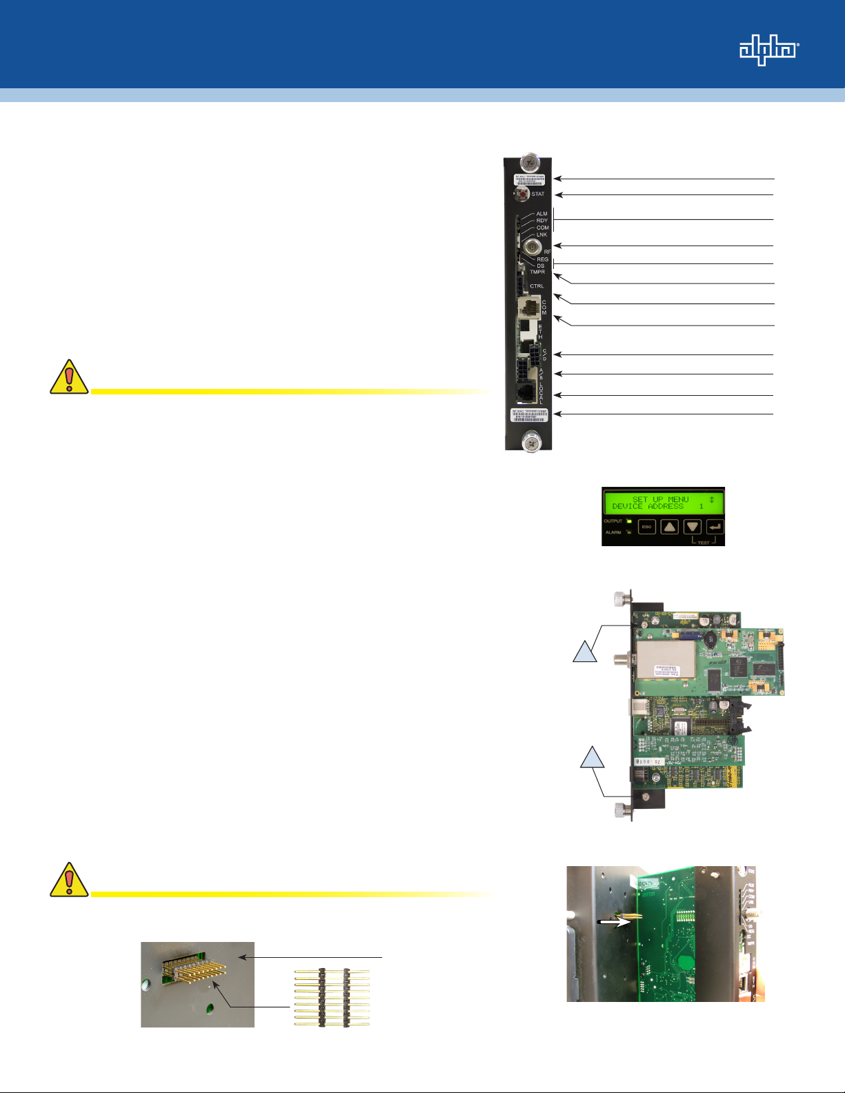
The RF (modem) and CPE (Dual-IP) MAC Addresses are printed
on barcode labels on the front and side of the DSM2 (Fig.1), as
well as on the packing slip.
• Provision the RF MAC Address with the proper DOCSIS®
conguration le.
• If operating in Dual IP Mode, provision the CPE MAC Address
so that it will be assigned a valid IP address on the public CPE
network through the modem.
CAUTION!
For units in service, backup battery power will not be available
during the following procedure.
Hardware Installation Procedure
Cable Modem Status LEDs
Tamper Switch Connection
Environmental Control (option)
AlphaBus Communication Port
Battery String Connection (C/D) (option)
Battery String Connection (A/B)
Local Port Connection
Modem's RF MAC Address
Fig. 1, Front view with callouts
Reset Button
Status LEDs
RF Connection
1. Verify the power supply device address is correct.
Power supplies should be assigned a unique address, e.g.,1, 2, or 3 (do
not use 0). No two power supplies monitored by a single DSM2 can have
the same address. The address can be changed in the SETUP menu of
the power supply's smart display (Fig. 2). See the power supply's technical
manual for more information.
2. Install the DSM2.
a. Turn off the XM2 battery breaker and disconnect all inverter module
connections.
b. Loosen the inverter module thumb screws and slide the inverter module
out of the power supply just far enough to disconnect the ribbon cable.
Disconnect the ribbon cable and remove the inverter module. If the
inverter module is equipped with a communication module, remove it
by loosening the two Phillips captive screws "A" (Fig. 3).
c. Insert the 18-pin jumper into the Inverter Module (Fig. 4).
(For earlier versions, insert the longer pins into the inverter
module).
d. Line up the 18-pin jumper with the DSM2 connector and connect the
unit to the inverter module (Fig. 5).
e. Tighten the two captive screws to secure the DSM2, re-install the
inverter module, reconnect the ribbon cable, tighten thumb screws and
inverter module connections.
Fig. 2, Smart Display
A
A
Fig. 3, Captive Screw location
CAUTION!
Verify the battery breaker remains in the OFF position.
Inverter Module
Fig. 4, 18-pin Jumper Installation Location
Fig. 5, Inverter Module, DSM2 connction
Page 2
Total Power Solutions
3. Make Battery Sense Wire Kit connections.
See the battery diagrams that came with the sense wire kit or reference the DSM2 Technical Manual.
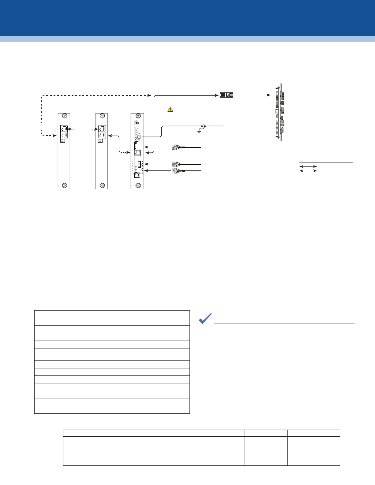
4. Connect the RF drop and make front panel connections.
The DOCSIS specication for downstream power level is ± 15dBmV. However, for optimal performance, set the level as close to 0
dBmV as possible.
Communications
Port
Serial Interface Card
(P/N 704-742-20)
XM2 XM2
S
Y
System Port
S
C
O
M
Serial Interface Card
(P/N 704-742-20)
S
Y
S
C
O
M
Communications
Port
Battery String
Connectors
“Master”
XM2
STAT
ALM
RDY
COM
LNK
REG
DS
TMPR
CTRL
O
C
A
L
ECM to SCM Interface
Required
Grounded Surge Protector
(Alpha P/N 162-028-10 or equivalent)
(Alpha P/N 704-709-20)
RF Cable to Headend
RF
Environment Control Wire
C
O
M
E
T
H
C
D
A
B
L
(Alpha P/N 875-627-20) to Heater Mat, Fan, etc.
To Battery Sense Wire Harnesses
Generator (ECM)
(Alpha p/n 744-726-XX)
ECM Technical Manual p/n 744-862-C0
available at: www.alpha.com
Legend:
Connections
Connections with more
than one power supply
5. Initial Start-up and Test.
Plug the power supply into the AC outlet and turn on the battery breaker (XM2-HP units perform a 10-second self test to check the
batteries).
The DSM2 LEDs blink three times and the RDY light begins blinking on and off.
Verify the DS and REG LEDs are on solid. This veries that the DSM2 has registered an IP address on the public network.
Verify LNK LED is ashing in Single IP mode, or ON solid in Dual IP mode.
Verify no XM2 alarms are active.
6. Test the Connection.
With the DSM2 used in conjunction with the XM2-HP power supply, connectivity can be veried via the XM2-HP smart display.
Otherwise, test the connection with a personal computer and a Local Port Adapter Cable (Alpha P/N 745-826-21). Terminal
Emulation software is necessary (e.g., HyperTerminal). Serial communication settings are:
Baud: 19200; Data Bits, 1; Parity, None; Stop Bits, 1; Flow Control None
To test the connection, launch the terminal emulation software and press ENTER.
Type SNAPSHOT, then press ENTER Description
MAIN > SNAPSHOT
CM MAC 000308142452 MAC address of the cable modem
CPE MAC 0090EAA0F269 MAC address of the CPE Device
CM 192.168.1.204 IP address of the cable modem
CPE 192.168.1.205 IP address of the CPE device (dual IP mode
only)
BATT 1A-2A 13.4 13.4 Power supply battery voltages
BATT 3A-4A 13.7 --.- Power supply battery voltages
CM TX (dBmV) 47.2 Cable modem transmit level
CM RX (dBmV) 8.5 Cable modem receive level
CM Ver 1.38 Cable modem rmware version
DSM VERV 2.02.1 Transponder processor rmware version
MAIN>
For contact information visit www.alpha.com
The Alpha Group >
Nort h Amer ica Europ e, Middl e East & Af rica Asia Pa cic Latin & South Am erica
USA Cyprus Germany Lithuania P.R. China Contac t USA ofc e
Tel: +1 360 647 236 0 Tel: +357 25 375 675 Tel: +49 9122 7988 9 0 Tel: +370 5 210 5291 Tel: +852 2736 86 63
Fax: +1 360 671 493 6 Fax: + 357 52 3 59 595 Fax: +49 912 2 79889 21 Fax: +370 5 210 5292 Fax: +852 2199 79 88
Canada Russia United Ki ngdom
Tel: +1 604 430 1476 Tel: +7 495 925 984 4 Tel: +44 1279 501110
Fax: +1 604 4 30 8908 Fa x: +7 495 916 1349 Fax: +44 1279 659 870
Alpha Technologies reserves the right to make changes to the products and information contained in this document without notice.
Copyright © 2009 Alpha Technologies. All Rights Reserved. Alpha® is a registered trademark of Alpha Technologies.
NOTE:
The procedure shown at left will allow you to see MAC
addresses, useful in working with network registration. IP
addresses can help determine if the transponder is recognized
by the management system, and if the transponder is in single
or dual IP operation (in dual IP, the CPE and CM will have an IP
address; in single, only the CM will have an IP address). Correct
battery voltages verify that the battery sense cable is connected
properly. Cable modem transmit and receive levels will be
helpful in verifying proper padding at the RF drop.
745-814-B6-001 Rev. A (03/09)
 Loading...