

Page 1

2007/02/23
DS16 OPERA TIONS MANUAL
Ring Communications, Inc.
1
Crisis Alert System
Direct Select Annunciator
16 Button
DS16
Page 2

2
DS16 OPERA TIONS MANUAL
2007/02/23
Page 3

2007/02/23
DS16 OPERA TIONS MANUAL
3
Contents
INTRODUCTION ............................. 5
INSTALLATION............................... 5
INTRODUCTION............................................................................................................................... 5
J1 - 8 pin (RJ45) Network connections : ........................................................................................... 5
Defaulting Configuration Memory ..................................................................................................... 6
Setting Network and Node Address ................................................................................................... 6
SWITCHES AND INDICATORS - ................................................................................................... 6
.............................................................................................................................................................. 6
OPERATION................................................................................. 7
CONFIGURATION........................... 8
SYNTAX......................................................................................... 8
TYPE FONTS ...................................................................................................................................... 8
COMMAND........................................................................................................................................ 8
PROMPT ............................................................................................................................................. 8
ERROR HANDLING......................................................................................................................... 9
HELP ............................................................................................. 9
HELP COMMANDS .......................................................................................................................... 9
CALL NUMBERS....................................................................... 10
BUTTON ADDRESS................................................................... 11
BACKUP ..................................................................................... 12
Page 4
4
DS16 OPERA TIONS MANUAL
2007/02/23
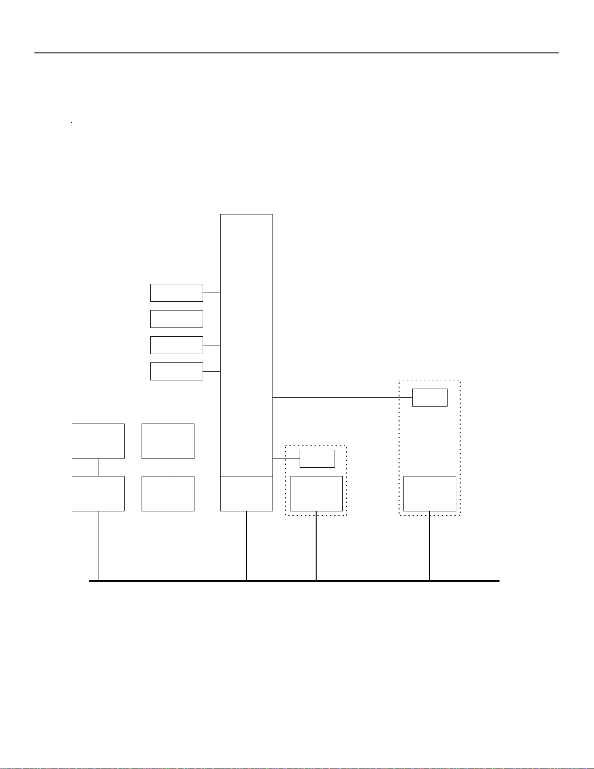
CRISIS ALERT
DS16
SUBSTATION
SUBSTATION
PC
DNA100
NODE 2
SUBSTATION
SUBSTATION
LOG
PRINTER
PRINTER
(DNA100)
NODE 3
RM5000
(CB901)
AA916
DXC910
(DXC901)
NODE 0
1 PAIR RS485
PACKET SWITCHED
LOCAL AREA NETWORK
MAX 8 NODES
DAD104
NODE 1
VOICE/POWER
AA916
DS16
NODE 4
2002/11/5
Page 5

2007/02/23
DS16 OPERA TIONS MANUAL
5
INTRODUCTION
The DS16 can be interfaced to the Crisis Alert Network for the purpose of handling incoming and outgoing calls
associated with one of the Crisis Alert master st ations.
Each DS16 must be asigned to a master station in the exchange controller DXC901/DXC910 (the same way as
when using DAD104).
INSTALLATION
INTRODUCTION
The DS16 operates on +24 VDC. It can be powered from the central exchange or can be powered locally by a
separate 24 VDC regulated power supply .
The recommended cord is the BF640A to connect the DS16 to the RJ45 network jack, KB171. Cords and jacks
must be ordered separately .
J1 - 8 pin (RJ45) Network connections :
One modular jack is provided at the back of the DS16. Use modular cables with straight through pin configuration only! An 8-pin (RJ45) modular jack (KB171) and cord (BF640A) are required for connection to the network.
PIN# - DESIGNA TION
1 - No connection.
2 - +12 VDC power input
3 - Data + (positive)
4 - No connection.
5 - No connection.
6 - Data - (negative)
7 - -12 VDC power input
8 - External Alarm.
Page 6

6
The maximum total network length is 7000 feet. A unshielded twisted pair cable should be used for the dat a pair (24
or 22 A WG).
Connect the DA T A pair from the network to pins 3 and 6 of the RJ45 wall jack maint aining polarity of the pair .
If a remote power source is being used, the negative side of the supply must be referenced to Earth Ground, as well
as, the CB901/RM5000 power supply .
DS16 OPERA TIONS MANUAL
2007/02/23
Defaulting Configuration Memory
Clear Memory: Set DIP switch SW2 1-8 to off . Push RESET. Master light will st art to flash when done.
Set Network and Node Address. Push Reset. The DS16 is now ready to be configured.
Preset Memory: Set DIP switch SW2 1-8 to on . Push RESET. Master light will start to flash when done.
Set Network and Node Address. Push Reset. The DS16 now has buttons 1-8 configured for call numbers 1 1-17.
Setting Network and Node Address
DIP switch SW2 is used to set the address of the DS16. See SETTING NETWORK ADDRESS of Chapter A -NETWORK
for a full description for setting addresses, as well as, an addressing chart.
SWITCHES AND INDICATORS -
SWITCHES
SW1 - Reset. Creates a local reset for this node only .
SW2 - Node & Network Address
L.E.D.’s
RUN - Indicates the local processor in the DS16 is running. Will illuminate after power up or reset.
MAST - Will light steady if this node is the master on the network. There can only be one master on each
network. On power up, each device waits for a response from a master . If no response is received,
then this device will take over as a master . Therefore, the first device powered up will be the master .
TX - Transmit data to the Network. Will flash when the DS16 sends data out on the Network. If the Master
LED is on, the TX LED will flash constantly. When the Master LED is off, TX will only flash when
transmitting to other devices.
RX - Receive data from the Network. Will flash when data is transmitted from another device to the
network. If the Master LED is on, the RX LED will flash when other devices respond to scanning
from the Master. When the Master LED is of f, the RX LED will flash constantly.
Page 7

2007/02/23
DS16 OPERA TIONS MANUAL
7
OPERATION
DIRECT SELECT BUTTONS
The DS16 has 16 buttons used for receiving or placing calls. Each button has a staus light.
The buttons are addressed in HEX from 0 to F .
Button 0 is upper left and button F is lower right. Call numbers may be programmed to buttons 1-F.
After a call button is programmed it can be used for answerring or placing a call to the programmed call number.
Button 0 is used for answering calls from call numbers that have not been programmed to any of the buttons,
and the call number of the calling station will displayed on the four digit numeric display .
FEA TURE BUTTONS
The DS16 has 4 buttons used for call handelling.
P: Park
X: Cancel
R: Remote control
BLANK: Not used
3
Answer key
4
Direct Select keys 1-7
6
Park key
2
Index paper
1
2
3
4
5
6
7
P
10:37
R
X
1
Call Status Lights (16)
8
9
A
B
C
D
E
F
Direct Select keys 8-15
4
8
Clock
Transfer status
Call Number
5
Remote control
key
7
Cancel key
Page 8

8
ST ATUS LIGHTS
Blinking Orange: Incomming Call or Alarm
Blinking Red: Incomming Fault
Solid Green: Call or Alarm or Fault has been answerred on this DS16.
Solid Orange: Call or Alarm or Fault has been answerred by another station.
Flashing Orange: Parked (on hold)
LED/KEY TEST
The test program is accessed with the following key sequence:
P-R-P-R
DS16 OPERA TIONS MANUAL
All lights turn on for the direct select keys Red+Green=Orange and 88:88 in the display .
When one of the Direct select keys is pushed the coresponding light turns Green,
and all the other lights turn Red.
If no keys are pushed for 10 seconds the DS16 returns to normal operation.
2007/02/23
OPTION MENU
The menu is accessed when pushing the blank key while in LED test mode.
Direct select 0-6 are used for selecting menu options.
0-Adjust Y ear
1-Adjust Month
2-Adjust Day
3-Adjust Hour
4-Adjust Minute
5-Adjust Second
6-Enable/Disable Time Display
Blank key = Increment
Park key = Decrement
Page 9

2007/02/23
DS16 OPERA TIONS MANUAL
CONFIGURATION
One DNA100 is used as a programming interface to the DS16. The DNA100 has one RS232 port
for connection to a PC running PROCOM+.
The DNA100 sets up a link between the PC and the DS16 on the RS485 network. The Configuration is
done from the PC and the information is stored in battery RAM in the DS16. When the system is first
installed the RAM must be reset before the system is configured (described earlier in this section). After
configuring the system the DNA100 may be removed.
SYNTAX
9
TYPE FONTS
boldface type
cr
indicates user input
Courier font indicates output
COMMAND
The command consists of a command word plus one or more parameters.
The command may be entered on one line with the parameters separated by spaces.
>command par1 par2 par3
cr
The command may be entered in prompt mode with parameters separated by carriage return. The prompt
will indicate what type of parameter value is required.
>command
Prompt>par1
Prompt>par2
Prompt>par3
cr
cr
cr
cr
>
PROMPT
< > Angle brackets enclose input parameters.
$ Hexadecimal value (default is decimal).
- Range of values may be entered.
.. Periods indicate that only ONE value is required from the range of values.
* Wild card means all values in a range of values.
/ Optional input selection separator.
Page 10

10
DS16 OPERA TIONS MANUAL
ERROR HANDLING
Misspelled command input will give the following error message:
Unknown Command
Parameter errors will print ERROR: and then prompt for the parameter again.
HELP
HELP COMMANDS
Help lists all help commands in the Configuration program. T ype HELP , H or ?.
>HELP
DS16 Command Summary:
====== =======================
H Help
? Help
LCN List Call Numbers
SBA Set Pushbutton Address
BAK Backup
>
cr
2007/02/23
Page 11

2007/02/23
DS16 OPERA TIONS MANUAL
11
CALL NUMBERS
All intercom stations are assigned call numbers in the Ring intercom central exchange.
The DS16 interface assigns a Push Button Address to each of the intercom call number for the external
device. This assignment is stored in the DS16 and may be listed with the command LCN from the PC
connected to the DNA100.
The call number may be 2,3 or 4 digit decimal.
The Push Button address is 1 digit HEX.
The Button may be removed from a a call number by entering 0 as the address.
>LCN
cr
Call Number <10-9999/*> : 10-20
Intercom Button NetSub
Call Number Address Address
============ ======== =======
11 1 801
12 2 802
13 3 803
14 4 804
>
Note! The NetSub is the Network Address and Line Equipment Number of the
intercom station. This information is used for testing only.
cr
Page 12

12
DS16 OPERA TIONS MANUAL
BUTTON ADDRESS
Assign a Push-Button to an intercom station.
PROGRAMMING
The following commands are used for this feature.
SBA Set Button Address
LCN List Call Number
Example: Set Button address for intercom call number 11 to address 1.
>SBA
cr
Call Number <10..9999> : 11
Button Address <0..F> : 1
>LCN
cr
Call Number <10-9999/*> : 11
Intercom Button NetSub
Call Number Address Address
============ ======== =======
11 1
cr
cr
cr
2007/02/23
>
Page 13

2007/02/23
DS16 OPERA TIONS MANUAL
BACKUP
Backup generates all programming commands required to restore the configuration of the DS16.
These commands may be downloaded and stored in a file on the PC. This file can then be uploaded to
restore the configuration of the DS16
PROGRAMMING
The following commands are used for this feature.
BAK Backup
Example:
>BAK
cr
Call Number <10..9999> : *
!
! BACKUP START: 2007/02/23
!
! DS16 VERSION: 2006/12/21
!
SBA 11 1
SBA 12 2
SBA 13 3
SBA 14 4
!
! END OF TRANSFER
cr
13
 Loading...