

Alpha DNA100, DNA100W User Manual

Chapter C
Ring Communications Inc.
Digital Network Adapter
DNA100
RING COMMUNICATIONS INC.

RING COMMUNICATIONS INC.

CHAPTER C
TABLE OF CONTENTS
DNA100 DIGITAL NETWORK ADAPTER ................................................................. C5
INTRODUCTION ............................................................................. C5
INSTALLATION .............................................................................. C6
Network connections ................................................................. C6
RS232 signals ...................................................................... C7
RS422 signals ...................................................................... C8
Setting Baud Rate / Selecting Device Type .............................................. C9
Communication Protocols ............................................................ C9
Setting Network and Device Address ..................................................C10
External Alarm Output ...............................................................C10
FRONT PANEL SWITCHES AND INDICATORS .................................................C11
MENU SYSTEM OPERATION ..........................................................................C12
MAIN MENU ................................................................................C12
MENU OPTIONS ............................................................................C12
STATUS DISPLAY ...........................................................................C14
Description of Status ................................................................C15
Description of Status Headings .......................................................C15
Additional Status For Master Display Line ..............................................C16
Operation ..........................................................................C16
NETWORK MONITOR .......................................................................C20
NETWORK INFORMATION ...................................................................C22
PACKET MONITOR ..........................................................................C24
ACTIVITY LOG PRINTER .............................................................................C26
Description of Status Headings .......................................................C26
Description of Status ................................................................C26
Additional Status For Devices ........................................................C27
RING COMMUNICATIONS INC.

October 2004 DIGITAL NETWORK ADAPTER DNA100
C4 RING COMMUNICATIONS INC.

October 2004 DIGITAL NETWORK ADAPTER DNA100
DNA100 DIGITAL NETWORK ADAPTER
INTRODUCTION
The Digital Network Adapter (DNA100) interfaces an external RS232 or RS422 device to Ring Communications'
Crisis Alert System. By setting DIP switches, the DNA100 can be selected to drive these devices:
Termina:l
The external device may be a VT100 Terminal or a PC with VT100 emulation software. The DNA100
is used to configure the following devices:
DXC901 Exchange controller for CB901
DXC910 Exchange controller for CB910/RM5K
DNA200 Video switcher
DNA300 Input Output Module
DNA400 Pocket page interface
A menu of options on the terminal also allow the user to set the Time/Date, List devices connected to
the Crises Alert Network ,View Errors on network, and Monitor network data traffic. The terminal may
also be used as an annunciator display. (see M ENU SYSTEM OPERATION).
Printer:
Provides an event activity log of all annunciation and event handling with time/date stamp (see
ACTIVITY LOG PRINTER).
The DNA100 operates on +24 VDC (+12, -12 VDC). It can be powered from a spare fuse in the CB901 central
exchange or can be powered locally by a separate 24 VDC regulated power supply.
The recommended cord is the BF640A to connect the DNA100 to the RJ45 network jack, KB171. Cords and
jacks must be ordered separately.
C5RING COMMUNICATIONS INC.
October 2004 DIGITAL NETWORK ADAPTER DNA100
INSTALLATION
Each DNA100 in a system can be individually powered from a fuse in the CB901 or a local power supply
operating off 24V regulated DC.
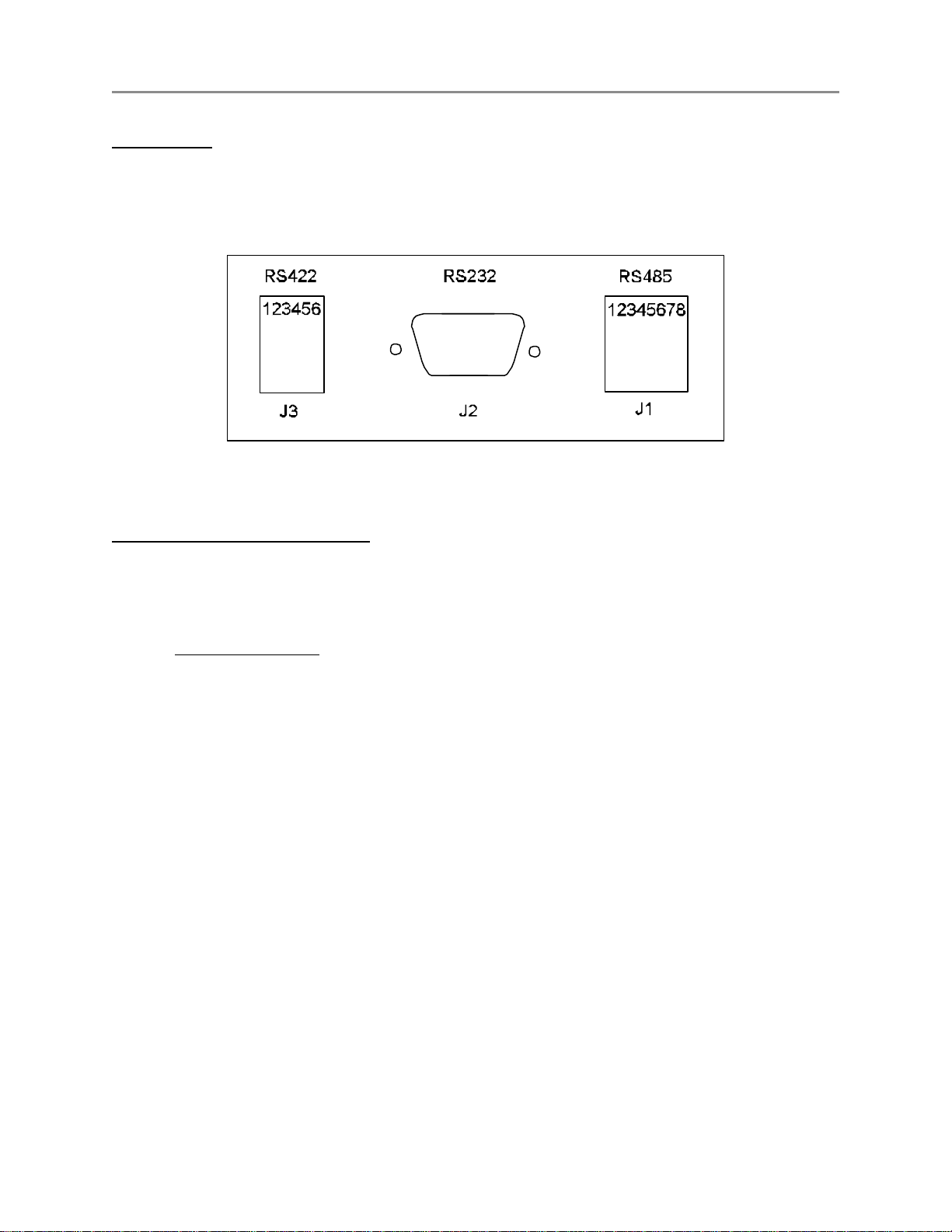
Figure C1 - Rear Panel Connectors
J1 - 8 pin (RJ45) Network connections :
Two modular jacks are provided at the rear of the DNA100. See Figure C1 . Use modular cables with straight
through pin configuration only! An 8-pin (RJ45) modular jack (KB171) and cord (BF640A) are required for
connection to the network.
PIN# - DESIGNATION
1 - No connection.
2 - +12 VDC power input
3 - Data + (positive)
4 - No connection.
5 - No connection.
6 - Data - (negative)
7 - -12 VDC power input
8 - External Alarm.
The maximum total network length is 7000 feet. A unshielded twisted pair cable should be used for the data
pair (24 or 22 AWG).
C6 RING COMMUNICATIONS INC.

October 2004 DIGITAL NETWORK ADAPTER DNA100
Connect the DATA pair from the network to pins 3 and 6 of the RJ45 wall jack maintaining polarity of the pair.
If a remote power source is being used, the negative side of the supply must be referenced to Earth Ground,
as well as, the CB901 power supply.
J2 - 9 pin (DB9) RS232 signals :
The DNA100 has a RS232 serial port interface, J2, that can connect to a terminal or printer. Check your
terminal, printer or video switcher manual for the correct RS232 connector type, input, output and handshaking
signal connections.
The maximum length for a RS232 cable connecting the DNA100 and other equipment is 50 feet.
A null-modem (LapLink) cable can be used to connect a DNA100 and a laptop or computer together if they are
close enough to each other.
If you are going to make your own cable the following is a description of the pinout of the DB9 connector on the
DNA100.
J2 SIGNAL
PIN# NAME
1 DCD
2 RXD
3 TXD
4 DTR
5 GND Signal Ground.
6 DSR Not used.
7 RTS Request to Send, output.
8 CTS Clear to Send, input.
9 RI Not used.
DIRECTION/
DESIGNATION
Data Carrier Detect, input.
Receive Data, input.
Transmit Data, output.
Data Terminal Ready, output.
C7RING COMMUNICATIONS INC.
October 2004 DIGITAL NETWORK ADAPTER DNA100
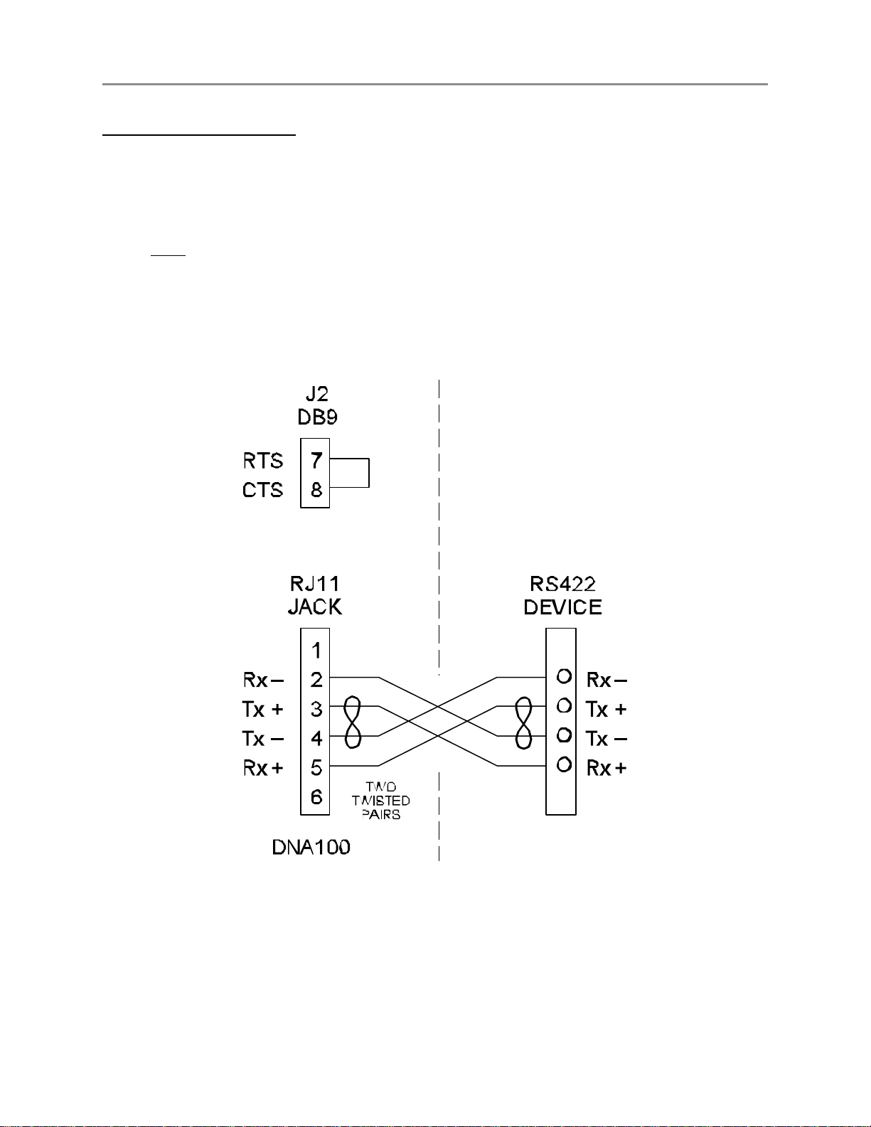
J3 - 6 pin (RJ11) RS422 signals :
A two twisted pair installation utilizing RS422 signals can be used to connect two bridges up to 7000 feet apart.
Use a six wire RJ11 cord with straight through wiring from J3 to another RJ11 jack on both sides of the
installation, and then use two twisted pairs between the two RJ11 jacks as shown in Figure C2.
A strap MUST be installed between RTS and CTS of J2 (DB9), in order to disable flow control for the RS422.
To do this, simply place a strap between pin 7 and pin 8 of J2. You could also solder this strap to a female
DB9 connector with solder lugs on the rear, then insert it into the J2 connector. Figure C2 illustrates the
strapping of J2.
Figure C2 - RS422 Interconnection
C8 RING COMMUNICATIONS INC.

October 2004 DIGITAL NETWORK ADAPTER DNA100
Setting Baud Rate / Selecting Device Type (For switch locations see Figure C3.)
DIP switches SW3-1 through SW3-6 are used to set the desired baud rate for the RS232 device. SW3-7 and
SW3-8 are used to select the RS232 device the DNA100 is driving (see chart below).
BAUD
RATE
1 2 3 4 5 6 7 8
19200 1 0 0 0 0 1 Terminal 0 0
9600 1 0 0 0 1 0 0 = off Printer 0 1
4800 0 1 0 0 0 1 1 = on Not used 1 0
2400 0 1 0 0 1 0 Not used 1 1
1200 1 0 0 0 1 1
Note! The Video switcher software is moved to DNA200
The I/O Module software is moved to DNA300
SW3
DEVICE
SW3
Communication Protocols
Aside from the baud rate, the terminal emulation should be set for VT100.
The DNA100 has No Parity, 8 Data Bits, and 1 Stop Bit.
Hardware flow control is used (RTS/CTS). The DNA100 will send data only if CTS is high from the other device.
Compatible emulation software:
Procomm Plus
Terminal for Windows 3.11
Hyper Terminal for Windows 95/98
Set software flow control to OFF and hardware flow control to ON.
Set Pace character to >
C9RING COMMUNICATIONS INC.
 Loading...