

Page 1

n Operator’s Manual
n Redundant Control Unit
FOR CFR UNINTERRUPTIBLE POWER SUPPLIES
FROM ALPHA TECHNOLOGIES
Page 2

TABLE OF CONTENTS
1. Introduction.......................................................................................................1
1.1 The Alpha Redundant Control Unit (RCU)................................................................... 1
1.2 A Tour of the RCU ........................................................................................................ 2
1.2.1 Front P anel......................................................................................................... 2
1.2.2 RCU Interior....................................................................................................... 4
1.2.3 Rear Panel......................................................................................................... 6
2. Installation.........................................................................................................7
2.1 Unpacking and Inspection Checklist............................................................................ 7
2.2 Rack Mount Installation................................................................................................ 8
2.3 Wall Mount Installation.................................................................................................9
3. Operation....................................................................................................10
3.1 RCU Start–Up and Test Procedure............................................................................ 10
3.2 RCU Voltage Configuration ....................................................................................... 13
4. Maintenance ...............................................................................................15
4.1 Internal Fuse Replacement ....................................................................................... 15
4.2 Troubleshooting.........................................................................................................16
4.3 RCU Wiring Diagrams ............................................................................................... 17
4.4 Return Instructions..................................................................................................... 18
4.5 Specifications ............................................................................................................ 19
4.6 Warranty ....................................................................................................................20
Page 3
1 Introduction
g
y
y
1.1 The Alpha Redundant Control Unit (RCU)
Purpose: Describes the operation of Alpha’s Redundant Control Unit (Figure
1.1)
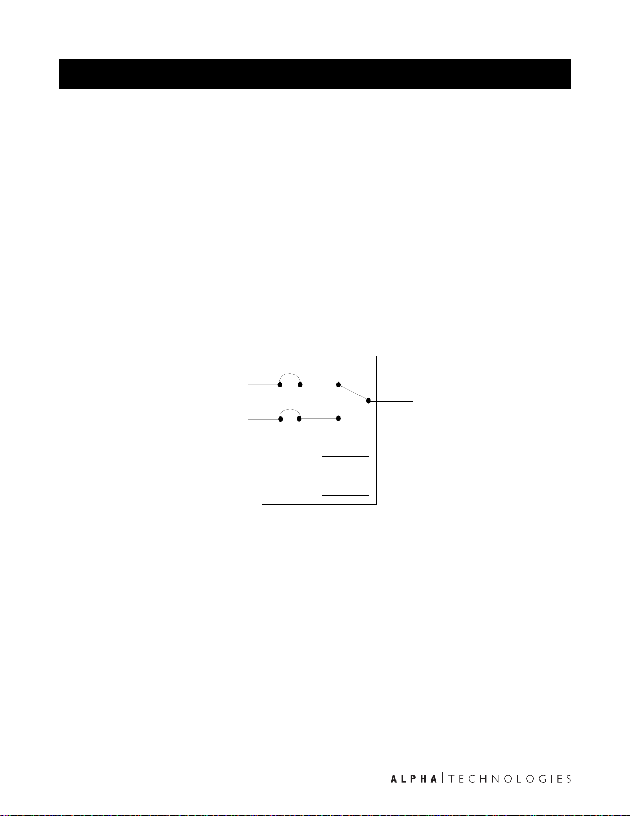
Alpha’s Redundant Control Unit (RCU) provides a dual–redundant configuration, ensur ing
power is always supplied to the critical load. Both input voltages are monitored, so if power is
lost at input 1, the RCU transfers to input 2. Input 1 is the primary source of power so the RCU
automatically returns to it when power is restored. Before transferring, it waits about 1 minute
to allow input voltage and frequency to stabilize.
The RCU has two contactors, one for each po wer source . They both cannot be on at the same
time. If there is a f ailure in either contactor or the control logic , the Type C alarm contact on the
rear panel is activated and the “Red Alert” LED turns on. Alarm conditions are: logic f ailure;
Contactor 1 or 2 fails to open; Contactor 1 or 2 f ails to close or open internal fuses. The front
panel LEDs shows the RCU’s status.
Inputs
Secondar
Primar
Contactor 1
Contactor 2
Figure 1.1
RCU Operating Diagram
Lo
Output
ic
1
Page 4

1 Introduction
1.2 A Tour of the RCU
Purpose: Describes the RCU’s controls, displays and terminal blocks
(Figures 1.2, 1.3, 1.4, 1.5).
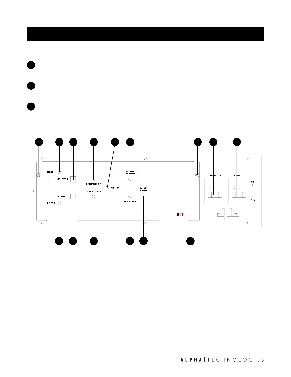
1.2.1 Front Panel (Figure 1.2)
1
Input 1 LED:
Shows the presence of AC power at Input 1.
2
Input 2 LED:
Shows the presence of AC power at Input 2.
3
Contactor 1 LED:
Shows Contactor 1 is closed, providing primary power to the output.
4
Contactor 2 LED:
Shows Contactor 2 is closed, providing secondary power to the output.
5
Output LED:
Shows there is power at the output.
6
Manual T ransfer LED:
Shows both primary and secondary power sources are in phase and that a manual transfer
can be done with the make–before–break manual bypass switch.
7
Red Alert LED:
Shows that one of the contactors or the control logic has failed.
8
Input 1 Circuit Breaker:
Provides circuit breaker protection to the primary input and acts as an ON/OFF switch.
9
Input 2 Circuit Breaker:
Provides circuit breaker protection to the secondary input and acts as an ON/OFF switch.
10
Select 1 Switch:
Opens the secondary contactor before closing the primary to provide Input 1 power to the
output.
11
Select 2 Switch:
Opens the primary contactor before closing the secondary to provide Input 2 power to the
output.
2
Page 5
1 Introduction
1.2 A Tour of the RCU
1.2 A Tour of the RCU (Continued)
1.2.1 Front Panel (Continued)
12
Alarm Reset Switch:
Shuts off the audible Red Alert alarm.
13
Attachment Screws:
These two screws secure the front panel to the RCU .
Front Panel:
14
This hinged panel opens downward to access the interior for voltage configuration, fuse
changing or troubleshooting.
13
1 10 5
2
11
3
4
6
127
Figure 1.2
RCU Front Panel
14
13
9
8
3
Page 6

1 Introduction
1.2 A Tour of the RCU
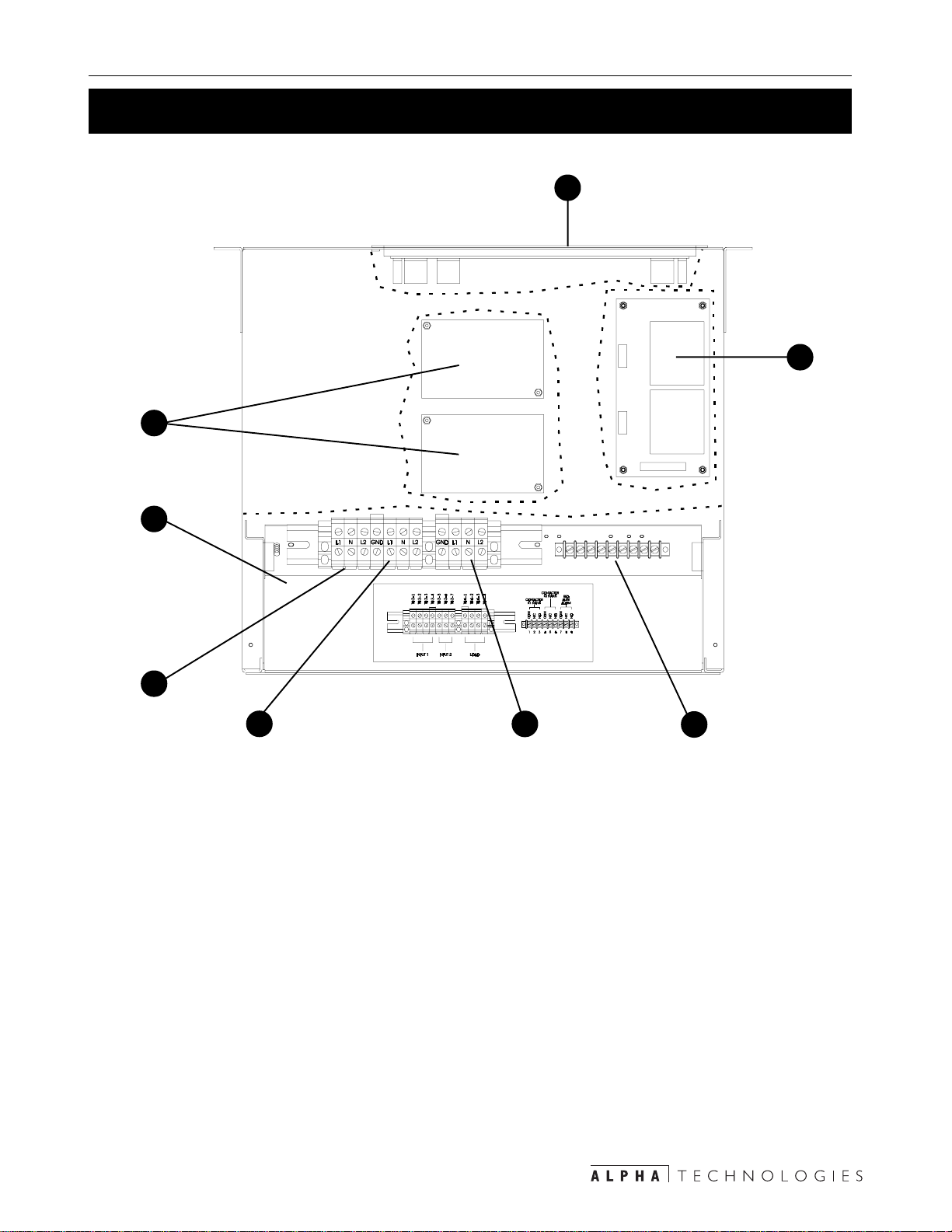
1.2.2 RCU Interior (Figure 1.3)
Front Panel:
1
This hinged panel opens downward to allow the operator access to the RCU interior to
configure the input/output voltage, replace fuses or f or troub leshooting. Two , 3.15 Amp
fuses are located here.
2
Contactors:
The primary and secondary contactors.
3
Sliding Panel:
This panel slides back and forth for access to the RCU’s input, output and alarm terminal
blocks.
4
Input 1 Terminal Block:
This terminal block is the primary power input.
5
Input 2 Terminal Block:
This terminal block is the secondary power input.
6
Output T erminal Bloc k:
This terminal block is the RCU’ s output.
Alarm Terminal Block:
7
This terminal block is the RCU’s alarm connection.
8
Power Board:
The RCU is configured here for 120, 208 or 240 VA C operation. Two, 500 mA fuses are
located on this board.
4
Page 7
1.2 A Tour of the RCU
1 Introduction
1.2.2 RCU Interior (Continued)
2
3
1
8
4
5
Figure 1.3
RCU Interior (Cutaway View)
6
7
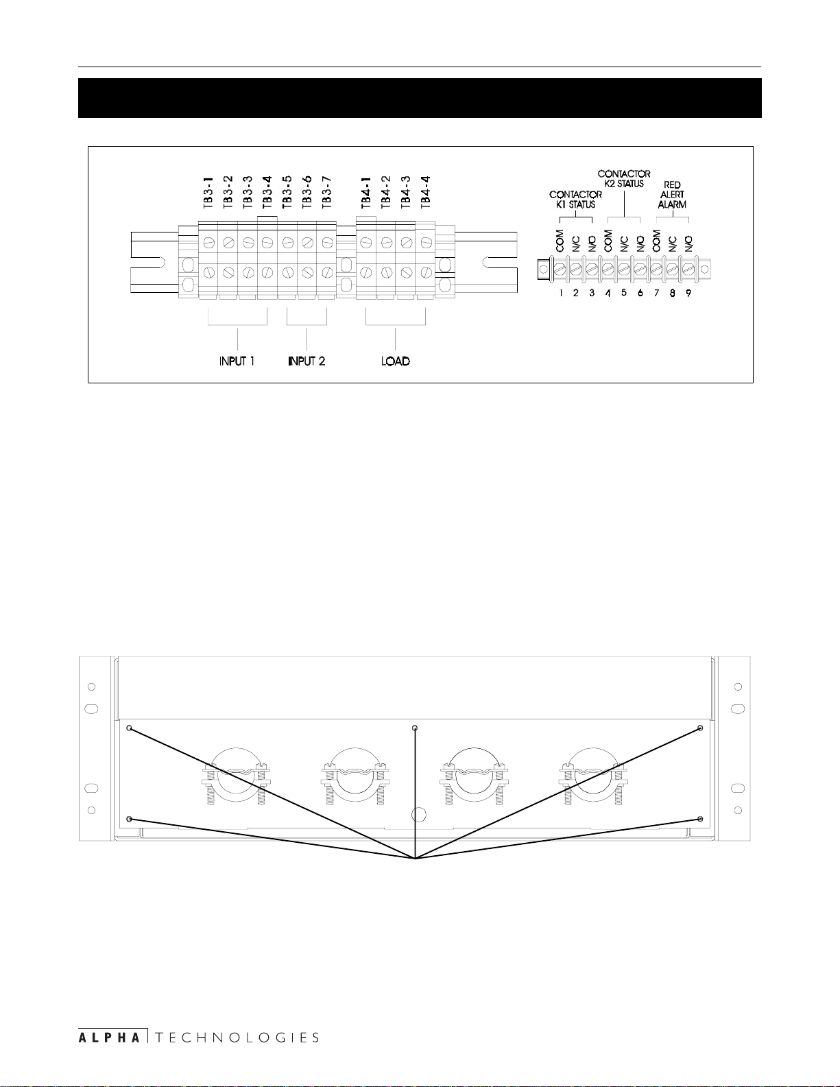
Wiring:
The wiring diagram for the terminal blocks is shown in Figure 1.4. Both Inputs share a common ground.
The alarm terminal block has Type C contacts to provide Contactor and Alarm status to the
monitoring system.
• Contactor K1 is normally closed.
• Contactor K2 is normally open.
• Red Alert Alarm is open when the system is operating normally.
5
Page 8
1 Introduction
1.2 A Tour of the RCU
L1
L2 L2
L1
NN
L2
GNDGND
L1N
Legend:
COM: Common, N/C: Normally Closed, N/O: Normally Open
Figure 1.4
RCU Wiring Diagram
1.2.3 Rear Panel (Figure 1.5)
To access the terminal blocks, unscrew the five attachment screws then remove the panel.
SOURCE 1 SOURCE 2 OUTPUT ALARMS
Attachment Screws
Figure 1.5
RCU Rear Panel
6
Page 9

2 Installation
2.1 Unpacking and Inspection Checklist
Carefully inspect the contents. If items appear damaged or missing, contact Alpha Technologies and the shipping company immediately. Most shipping companies have only a short
claim period. Make sure the following have been included:
Redundancy Control Unit and mounting kit.
Operator’ s Manual
Any other ordered options
SAVE THE ORIGINAL SHIPPING CONTAINER
If the RCU is returned for servicing, pack it in its original shipping
container. Alpha Technologies is not responsible for damage
caused by improper packaging of returned units.
READ THE OPERATOR’S MANUAL
Become familiar with the RCU by reviewing the procedures and
drawings in this manual before installation. If you have questions
contact Alpha Technologies.
COMPLETE THE FOLLOWING FOR Y OUR RECORDS:
Model
Serial Number
Options
Purchase Date
This Unit was purchased from:
Dealer Name
City
State/Province
ZIP/Postal Code
Country
Telephone/ Fax Number
E–Mail
7
Page 10

2 Installation
2.2 Rack Mount Installation
NOTES: 1) The RCU can be mounted in either a 19 or 23 inch ra c k b y adjusting the configur a-
tion of the rack mount brackets.
2) Use #4 AWG f or connecting the input and output terminal bloc ks and #18–22 AWG
solid wire for connecting the communication terminal block.
3) DANGER: Before installation, make sure the Input 1 and 2 circuit breakers are
OFF.
4
Wire the load(s)
to the output
terminal block with
#4 AWG
3
Wire the communication
lines to the communication
terminal block with #18–22
gauge solid wire
Mid Mount
Attachment Points
1
5
Wire the inputs
to the input
terminal block with
#4 AWG
Attach the RCU
2
to the rack
Attach the rack mount brackets
to the RCU in either the front
or mid mount position
Figure 2.1
RCU Rack Mounting
8
Page 11
2 Installation
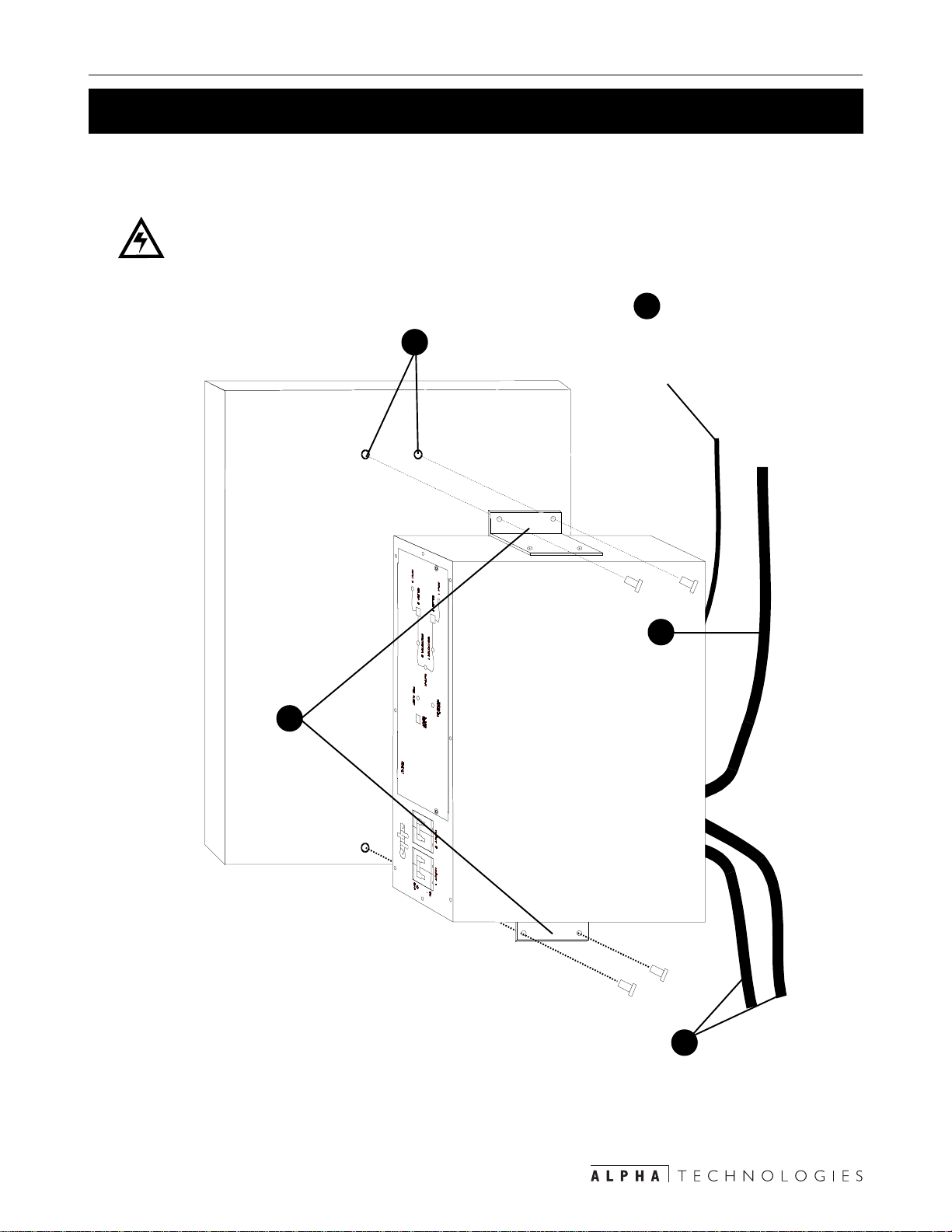
2.3 Wall Mount Installation
NOTES: 1) Use #4 AWG for connecting the input and output terminal bloc ks and #18–22 AWG
solid wire for connecting the communication terminal block.
2) DANGER: Bef ore installation, mak e sure the Input 1 and 2 circuit break ers are
OFF.
3
Wire the communication
Attach the RCU to the wall
2
lines to the communication terminal block with
#18–22 AWG solid wire
Attach the rack mount
brackets to the RCU
Wire the load(s)
to the output
terminal block with
#4 AWG
1
Figure 2.2
RCU Wall Mounting
4
5
Wire the inputs
to the input
terminal block with
#4 AWG
9
Page 12

3 Operation
3.1 RCU Start–Up and Test Procedure
WARNING: Before starting, turn OFF the Input 1 and 2 Circuit Breakers and the Load(s).
NOTE: If there is an y type of logic or contact f ailure during the system start-up, test or opera-
tion, the Red Alert LED turns ON.
STEP 1: RCU Power Up
Press the Select 1
contactor switch.
2
Figure 3.1
RCU Power Up
Switch ON both
1
circuit breakers.
STEP 2: Test Primary Power
1
Switch the Input 1 circuit breaker OFF.
The Input 1 LED on the front panel will go out, showing the loss of primary power. As the
RCU transfers to the secondary power source the Contactor 2 LED turns ON.
NOTE: There will be a five second delay between the transf er from Input 1 to Input 2. This
conforms to the automatic transfer switch safety code.
Input 1 LED
Contactor 2 LED
Figure 3.2
Testing Primary Power
10
T urn OFF
Input 1 circuit breaker
Page 13

3 Operation
3.1 RCU Start–Up and Test Procedure
STEP 3: Restore Primary Power
Switch the Input 1 circuit breaker ON.
1
The Input 1 LED lights, showing the return of primary power. The RCU transf ers back to
Input 1 after about 30 seconds, after the voltage and frequency stabilizes . When done, the
Contactor 1 LED turns ON.
Turn ON
Input 1 LED
Contactor 1 LED
Input 1 circuit breaker
Figure 3.3
Return Primary Po wer
STEP 4: Test Secondary Power
1
Switch the Input 2 circuit breaker OFF.
The Input 2 LED on the front panel turns OFF, indicating the loss of secondary power.
There should be no transfer or an y other change in the status of the RCU.
Switch the Input 2 circuit breaker ON to return to normal status.
2
T urn OFF
Input 2 LED
Input 2 circuit breaker
Figure 3.4
Test Secondary Power
11
Page 14

3 Operation
3.1 RCU Start–Up and Test Procedure
STEP 5: Test Secondary Contactor
1
If the RCU’s Contactor 1 LED is ON:
Press the Select 2 switch. As the RCU transfers to the Secondary power source the
Contactor 2 LED turns ON.
Press the Select 1 switch to return to primary power.
2
Select 2 Switch
Contactor 2 LED Red Alert LED
Contactor 1 LED
Figure 3.5
Test Secondary Contactor
STEP 6: Turn On The Loads
If the Manual Tr ansf er LED is ON, turn on the load(s).
12
Page 15
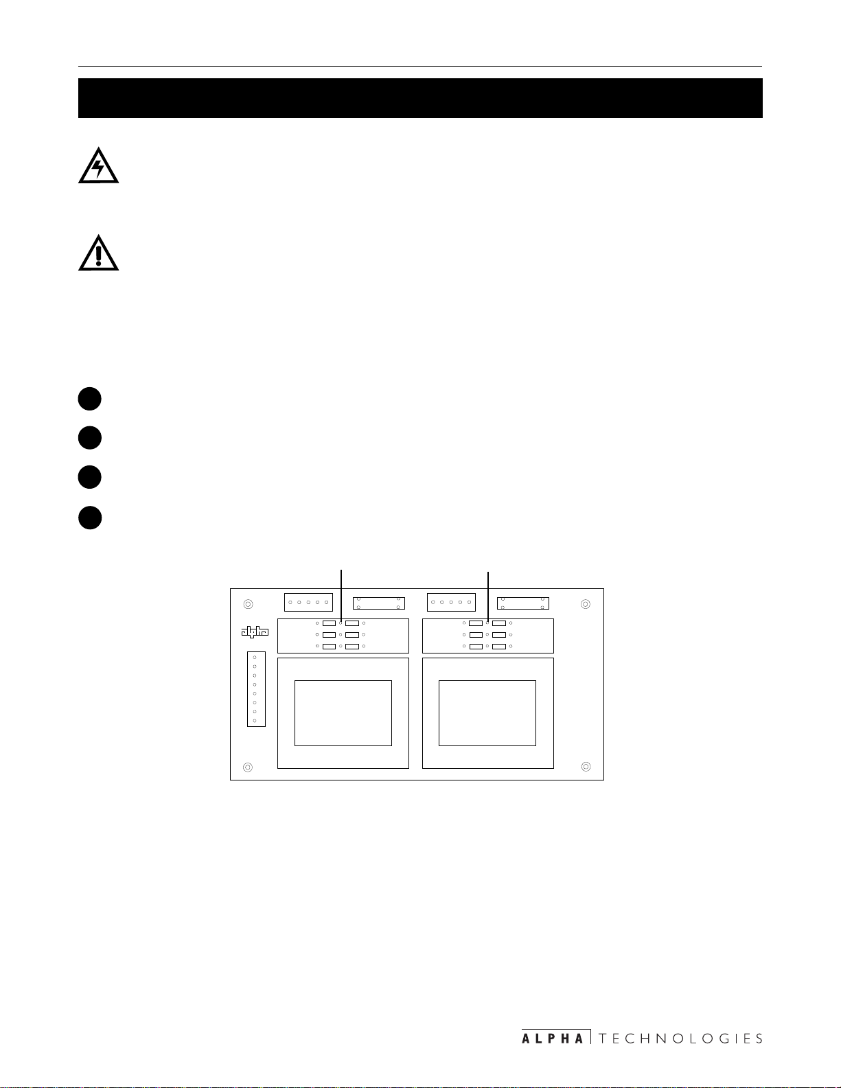
3.2 RCU Voltage Configuration
DANGER: This procedure should be done only by qualified personnel.
DANGER: V erify the power is OFF before opening the front panel.
NOTE: The Input 1 and 2 voltages must be configured identically.
The RCU is designed so it is voltage configurable for 120/208/240 VAC.
PROCEDURE:
Switch the Input 1 and 2 circuit breakers OFF.
1
2
Remove the two Phillips screws on the sides of the front panel.
3 Operation
3
Carefully lower the panel 45 degrees.
Locate the Input 1 and 2 pin jumpers on the power board.
4
Input 1 Pin Jumpers Input 2 Pin Jumpers
J 1
1122334455
R 3 R 4
R 2
120 V
R 1
J 3
12345678
F 1
R 5
R 6
208 V
or
240 V
J 2
R 9
120 V
R 8
R 7
Figure 3.6
Input 1 and 2 Pin Jumpers on the Power Board
R 10
R 11
R 12
F 2
208 V
or
240 V
13
Page 16

3 Operation
3.2 RCU Configuration Procedure
Position jumpers or 0 Ohm resistors according to the following chart.5
deriuqeRderiuqeR
deriuqeRderiuqeR
deriuqeR
segatloV
tnemecalPrepmuJtnemecalPrepmuJ
tnemecalPrepmuJtnemecalPrepmuJ
tnemecalPrepmuJ
*1tupnI
tnemecalPrepmuJtnemecalPrepmuJ
tnemecalPrepmuJtnemecalPrepmuJ
tnemecalPrepmuJ
*2tupnI
CAV021CAV021
CAV021CAV021
CAV021
CAV802CAV802
CAV802CAV802
CAV802
CAV042CAV042
CAV042CAV042
CAV042
* NOTE: Input 1 and Input 2 must always
be configured for the same voltage
Figure 3.7
Input 1 and 2 Jumper Configuration
6
Verify the Input 1 and 2 voltages are configured identically.
7
Close the front panel.
Test it for proper operation (Section 3.1) and required v oltages .
8
3R,2R,1R9R,8R,7R
6R,5R,4R21R,11R,01R
6R,5R,4R21R,11R,01R
14
Page 17

4 Maintenance
4.1 Internal Fuse Replacement
DANGER: Fuse replacement should be done only by qualified personnel.
DANGER: Make sure the power is OFF before opening the front panel.
The RCU has four internal fuses that are accessible from the front panel.
To lower the front panel:
1
Switch OFF the Input 1 and 2 circuit breakers.
Remove the two Phillips screws on the RCU front panel.
2
3
Carefully lower the front panel forward 45 degrees.
Two fuses are located on the power board: Input 1: F1 and Input 2: F2 (both are 500 mA).
Input 1 Fuse
(500 mA)
J 1
1122334455
R 3 R 4
R 2
120 V
R 1
J 3
12345678
F 1
J 2
120 V
R 9
R 8
R 7
208 V
R 5
or
240 V
R 6
Input 2 Fuse
(500 mA)
F 2
R 10
208 V
R 11
or
240 V
R 12
Figure 4.1
Power Board Fuse Location
Two fuses are located on the logic board: Contactor 1: F1 and Contactor 2: F2 (both are
3.15 Amps).
Logic Board
K1
K3
F1
3.15 Amp
Figure 4.2
Logic Board Fuse Location
15
F2
3.15 Amp
Page 18

4 Maintenance
4.2 Troubleshooting
The most common problems, symptoms and causes are listed in Figure 4.3. It starts off with
the simplest problems, working to the most complex. If the operator can’t resolve the problem,
contact Alpha Technologies. Maintenance and troubleshooting should be done only by qualified personnel.
MOTPMYSMOTPMYS
MOTPMYSMOTPMYS ESUACELBABORPESUACELBABORP
MOTPMYS
rehto
refsnarttonlliwUCRrefsnarttonlliwUCR
refsnarttonlliwUCRrefsnarttonlliwUCR
refsnarttonlliwUCR
ehtottupnInomorf
ESUACELBABORPESUACELBABORP NOITULOSNOITULOS
ESUACELBABORP
deppirtrekaerbtiucriCrekaerBteseR
wolootegatloVegatlovkcehC*
NOITULOSNOITULOS
NOITULOS
draobcigolnoesufnepOesuFecalpeR*
neporodesufrotcatnoCUCRecalpeR*
no"KOssapyBlaunaM"no"KOssapyBlaunaM"
no"KOssapyBlaunaM"no"KOssapyBlaunaM"
no"KOssapyBlaunaM"
nonruttonlliwUCR
esahp
deppirtrekaerbtiucriCrekaerBteseR
*
These Items are to be performed only by a qualified technician
Figure 4.3
Troubleshooting Chart
cigollortnochtiwmelborPUCRecalpeR*
fotuo2tupnIdna1tupnI
yrassecensa
tcerrocdnagnisahpkcehC*
16
Page 19

Input
y
CB Panel
Bypass
Input
W1
W5
Input
Breaker
Static
Switch
Battery
Breaker
Battery
Charger
CFR UPS
Inverte r
Normally
OFF
Isolation/Output
Wa ve form C on tro l
Output
Breaker
W 4
W 2
Input 1
Input 2
RCU
Logic
W 3
Optional Manual Bypass
Option XFMR
Line
RCU
Bypass
UPS
W 8
(W 9)
4.3 RCU Wiring Diagrams
Output
17
Input
CB Panel
Bypass
Input
Battery
W1
W5
Figure 4.4
RCU Wiring Diagram
CFR UPS
Static
Switch
Input
Breaker
Battery
Breaker
Battery
Charger
Battery
Inverter
Normall
OFF
Isolation/Output
W a ve form Co n tro l
Figure 4.5
RCU Wiring Diagram
(Without Manual Bypass Switch)
Output
Breaker
W 4
W 2
Input 1
Input 2
RCU
Logic
W 3
Output
4 Maintenance
Page 20

4 Maintenance
4.4 Return Instructions
Before returning an RCU to Alpha Technologies for repair, obtain a Return Material Authorization (RMA) number from Alpha’s customer service department. Clearly write it on the original
shipping container. If you do not have it, pack the substitute container with at least three inches
of shock–absorbing material. Do not use popcorn–type material. Returns should be prepaid
and insured (COD and freight collect cannot be accepted).
NOTE: Alpha Technologies does not assume responsibility for damage caused by improper packaging of returned units.
For parts and service, contact the Alpha Technologies Customer Service Department at:
setatSdetinU0632-746)063(
adanaC6741-034)406(
modgniKdetinU011224-9721-44+
ynamreG303799-2219-94+
tsaEelddiM576573-5-753+
ailartsuA6687-4982)0(16+
To obtain complete technical support (7
days a week, 24 hours a day) call:
USA 1–800–322–5742
CANADA 1–800–667–8743
18
Page 21

4.6 Specifications
4 Maintenance
snoitacificepSlareneGsnoitacificepSlareneG
snoitacificepSlareneGsnoitacificepSlareneG
snoitacificepSlareneG
spmA05spmA05
spmA05spmA05 spmA001spmA001
spmA05
*CAV,egatloVtupnI042/802ro021
zH,ycneuqerFtupnI36-74
spmA,tnerruCtupnI05001
spmA,rekaerBtupnI05001
spmA001spmA001
spmA001
,emiTrefsnarTlacipyT
06-04
)cesm(
gnitarepO
O
(erutarepmeT
)C
04+ot0
)mm/sehcnI(htdiW234/71
)mm/sehcnI(thgieH331/52.5
)mm/sehcnI(htpeD183/51
)gk/sbl(thgieW61/53
* Primary and secondary power source must have the same nominal voltage.
19
Page 22

4 Maintenance
4.6 Warranty
LIMITED 24-MONTH WARRANTY
AC PRODUCTS
Alpha Technologies warrants its equipment to be free of manufactur ing defects in material and workmanship
for a period of 24 months from the date of manufacture. The liability of Alpha Technologies under this warranty
is solely limited to repairing, replacing, or issuing credit for such equipment (at the discretion of Alpha
Technologies), provided that:
1.Alpha Technologies’ Customer Service Department is promptly notified, by facsimile or telephone, that a
failure or defect has occurred.
2.Alpha Technologies’ Customer Service Department issues a Return Materials Authorization (RMA) number,
and designates the service location. The RMA must be clearly marked on the outside of the shipping
container.
3. Purchaser is responsible for all in-bound shipping and handling charges (COD and freight collect will not
be accepted without prior approval from Alpha Technologies); Alpha Technologies will pay out-bound
surface shipping charges for return of repaired equipment.
4.A satisfactory examination of the returned unit by Alpha Technologies’ Service personnel shall disclose
that defects have not been caused by misuse, neglect, improper installation, repair, alteration, or accident,
or failure to follow instructions furnished by Alpha Technologies. If Alpha Technologies’ Service personnel
determine that the unit has been damaged due to one of these causes, or if the unit is free of defects, a
handling or repair fee may be assessed prior to returning the unit.
WITH RESPECT TO BATTERIES, PERIPHERAL DEVICES, ATTACHMENTS OR APPARATUS NOT
MANUF ACTURED BY ALPHA TECHNOLOGIES, ALPHA WILL ASSIGN T O THE PURCHASER ITS RIGHTS
UNDER THE ORIGINAL MANUF A CTURER’S W ARRANTY OF SUCH BA TTERIES , PERIPHERAL DEVICES,
ATTACHMENTS OR APPARATUS, BUT OFFERS NO ADDITIONAL WARRANTIES IN CONNECTION
THEREWITH.
THIS LIMITED 24-MONTH W ARRANTY IS IN LIEU OF ALL OTHER WARRANTIES , EXPRESS OR IMPLIED ,
INCLUDING, BUT NOT LIMITED TO , IMPLIED WARRANTIES OF MERCHANTABILITY AND FITNESS FOR
A PARTICULAR PURPOSE.
IN NO CASE SHALL ALPHA TECHNOLOGIES BE LIABLE FOR ANY INCIDENTAL, SPECIAL OR
CONSEQUENTIAL DAMA GES WHATSOEVER, INCLUDING WITHOUT LIMITA TION ANY CLAIM FOR LOST
PROFITS OR REVENUES, EVEN IF ALPHA TECHNOLOGIES HAS BEEN AD VISED OF THE POSSIBILITY
OF SUCH, FOR BREACH OF THIS OR ANY O THER WARRANTY, EXPRESS OR IMPLIED.
Any action for breach of this limited 24-month warranty must be brought within a period of 24 months from
date of manufacture.
This limited 24-month warranty does not extend to any unit that has been repaired or altered by any party
other than Alpha Technologies or its Authorized Service Center.
Alpha Technologies reserves the right to discontinue particular models and to make modifications in design
and/or function at any time, without notice and without incurring obligations to modify previously purchased
units.
8/96
20
Page 23

USA, LA TIN AMERICA & ASIA
P ACIFIC
Alpha Technologies
3767 Alpha Way
Bellingham, WA 98226
Tel: (360) 647–2360
Fax: (360) 671–4936
CANADA
Alpha Technologies
7033 Antrim Ave.,
Burnaby BC V5J 4M5
Tel: (604) 430–1476
Fax: (604) 430–8908
UNITED KINGDOM,
EUROPE & AFRICA
Alpha Technologies
Cartel Business Estate
Edinburgh W ay
Harlow, Essex
CM20 2DU
Tel: +44–1279–422110
Fax: +44–1279–423355
GERMANY
Alpha Technologies
Hansastrasse 8
D-91126 Schwabach
Tel: +49–9122–79889–0
Fax: +49–9122–79889–21
MIDDLE EAST
Alphatec
P.O. Box 6468
3307 Limassol, Cyprus
Tel: +357–5–375675
Fax: +357–5–359595
AUSTRALIA/SOUTH P A CIFIC
Alpha Technologies
8 Anella A ve., Unit 6
Castle Hill, NSW 2154
Tel: +61–2–9894–7866
Fax: +61–0–2–9894-0234
http://www.alpha.com
Alpha sales and service offices located throughout the world
Printed In Canada
020–145–B0–001 01/00
© 1999 Alpha Technologies
 Loading...