

Page 1

CFR
3000 and 3000RM
Uninterruptible Power Supplies
From Alpha Technologies
!!
! Operator ’s Manual
!!
Page 2
!!
!
!!
!!
!
!!
Operator’s Manual
CFR 3000 and 3000RM
Uninterruptible Power Supplies
LINE PRESENT
LINE FAILURE
SERVICE
LOW BATTERY
WARNING
LOW BATTERY
SHUTDO WN
TEST
ALARM
OFF
MANUAL
START
OUTPUT LOAD
OVERLO AD
100%
75%
50%
25%
Page 3
CFR 3000 and 3000RM
Save This Manual
It contains important installation and operating instructions.
Keep it in a safe place.
CAUTION
Risk Of Electrical Shock
T o reduce the risk of electrical shock and to ensure the safe operation of the CFR 3000 and
3000RM, these symbols are used throughout this manual. Where they appear only qualified
personnel should carry out the instructions.
A DANGEROUS VOLTAGE exists in this area. Use extreme caution.
ATTENTION: Important operating instructions. Follow them exactly.
NOTICE:
The CFR 3000 and 3000RM generates, uses and can radiate radio frequencies if not installed and
tested in accordance with the instructions contained in this manual. It has been tested and found to
comply with the limits established for a Class A computing device pursuant to part 15 of FCC rules
when it is operated alone. It also complies with the radio interference regulations of DOC which are
designed to provide reasonable protection against such interference when this type of equipment is
used in a commercial environment. If there is interference to radio or TV reception, which is determined by switching it on and off, relocate the equipment or use an electrical circuit other than the
one used by the CFR 3000 and 3000RM.
i
Page 4
Safety Checklists
DANGER: Do not expose the unit to rain or moisture.
DANGER: Sealed lead-acid batteries with high energy and chemical hazards are
used. This manual contains important operation and safety instructions. Only qualified
personnel should service the CFR 3000 and 3000RM.
CFR 3000 and 3000RM Safety Checklist
Carefully unpack the unit. Report any shipping damage at once.
CFR 3000 and 3000RM
Read this manual. If you have any questions about the safe installation, operation or maintenance of the unit, contact Alpha Technologies’ customer service department.
Before installation, confirm the voltage and current input requirements of the load(s) is
compatible with the unit’s output. Also see the line voltage and current is compatible with
the unit’s input requirements.
The unit should be installed on a dedicated circuit.
Wiring should be done to meet local electrical codes.
Place a warning label on the electrical panel to tell emergency personnel an
Uninterruptible Power Supply (UPS) is installed.
Use proper lifting techniques when lifting or moving the unit.
The unit has more than one live circuit. AC power may be present at the outputs even if the
unit is disconnected from line power.
Battery Safety Checklist
Always switch the unit’s battery circuit breaker off before connecting or disconnecting an
external battery back. This reduces the chance of a spark.
There are dangerous voltages inside the unit. Only qualified personnel should perform
installation and maintenance.
ii
Page 5

CFR 3000 and 3000RM
Safety Checklists (Continued)
Live battery wires must not touch the unit’s chassis or any other metal objects. This can
cause a fire or explosion.
Inspect the batteries once a year for signs of cracks, leaks or swelling. Replace as required.
When batteries are in storage, charge them at least once every three months for
optimum performance and to extend their lifetime.
Always replace batteries with ones of identical type and rating. Never install old or un-
tested batteries.
Use insulated tools during servicing.
Remove all rings, watches, jewelry or other conductive items before working inside the
enclosure.
Follow local regulations for the disposal of batteries. Recycling is the best method.
Never burn batteries to dispose of them. They may explode.
Do not open the batteries. The contents are toxic.
iii
Page 6

CFR 3000 and 3000RM
Table of Contents
The emergency shutdown procedure is on the inside rear cover
1. Introduction .........................................1
1.1 The CFR Advantage.................................. 2
1.2 Unpacking and Inspection Checklist......... 3
1.3 The Alpha CFR 3000 and 3000RM............ 5
2. Installation ..........................................10
2.1 Pre–Installation Checklist....................... 11
2.2 Installing the Unit ................................... 13
2.3 Connecting the Unit................................ 15
2.4 Connecting the External Battery Packs.. 18
2.5 Connecting the External Alarm Port ....... 20
2.6 Connecting the LAN Port........................ 21
2.7 Connecting the RS–232 Port .................. 22
2.8 Transformer Output Load Sharing ...........23
3. Operation ............................................26
3.1 Turning On the Unit ................................27
3.2 Turning Off the Unit ................................ 29
3.3 Testing the Unit ...................................... 30
3.4 Troubleshooting with the SID .................. 31
3.5 Controlling the Unit with the Standard
Interface Device ..................................... 32
4. Communication ............................. 35
4.1 RS–232 Set-Up ...................................... 36
4.2 Using the Opening Menu........................38
4.3 Menu Tree..............................................41
4.4 System, Input, Output & Battery Param-
eters ......................................................42
4.5 User Parameters ....................................45
4.6 Maintenance Parameters ....................... 49
4.7 Installing and Using the External Modem 50
5. Maintenance ....................................58
5.1 Testing the Battery Run Time ................. 59
5.2 Troubleshooting......................................60
5.3 Returning the CFR to Alpha for Repairs .. 62
5.4 Replacing the Internal Batteries.............. 62
5.5 Configuring the Input/Output Voltage ......67
5.6 Battery Run Times .................................70
5.7 Specifications.........................................72
Index ............................................ 73
Warranty ...................................... 78
iv
Page 7

1
Section 1
Introduction
This section introduces you to the Alpha
CFR 3000 and 3000RM UPS’s:
• The CFR advantage (Section 1.1).
• An unpacking and inspection checklist (Section
1.2).
• A tour of the unit, it’s connectors, switches and
control panels (Section 1.3).
Page 8

1 Introduction
2
1.1 The CFR Advantage
! Advanced Power Protection Technology
Alpha’s CFR Uninterruptible Power Supply (UPS) provides continuous and conditioned
computer-grade AC power for computer systems, point of sale terminals, process controls,
telecommunications, cable TV headend, broadband LAN, manufacturing control systems,
hospital critical care and lab equipment.
!
Rack or Tower Mounting
The unit comes in a rack mount case which can be fitted into any standard rack or a tower
case for mounting on the floor. The two units operate identically .
!
Regulation
The unit maintains ±1% output regulation without using the batteries. Even with input voltage
fluctuations as great as +10% or –20%, the output is constant regardless of the load’s size.
!
Isolation
The output is totally isolated from the input to protect the loads from spikes, surges and line
noise. The ferro resonant transformer provides nondegradable spike and surge protection.
! Extended Backup Cap ability
Alpha's EBP Series external battery packs extends backup time during power outages.
Installing the battery pack is as simple as plugging it in.
! Self Test Function
The built-in self test checks all critical areas, including the batteries, to ensure optimum performance.
! Load and Overload Information
The display panel shows the loading and tells you when the unit is overloaded.
! Generator Ready
The unit has frequency sense and constant slew frequency synchronization circuits for
trouble-free operation with most standby generators.
! Advanced Communications Capabilities
The RS–232 communications port is SNMP and modem compatible.
! Safety
Alpha designed the CFR to meet or exceed the UL, CSA or VDE safety standards. Our
commitment to safety makes Alpha T echnologies a leader in the power industry .
Page 9
3 1 Introduction
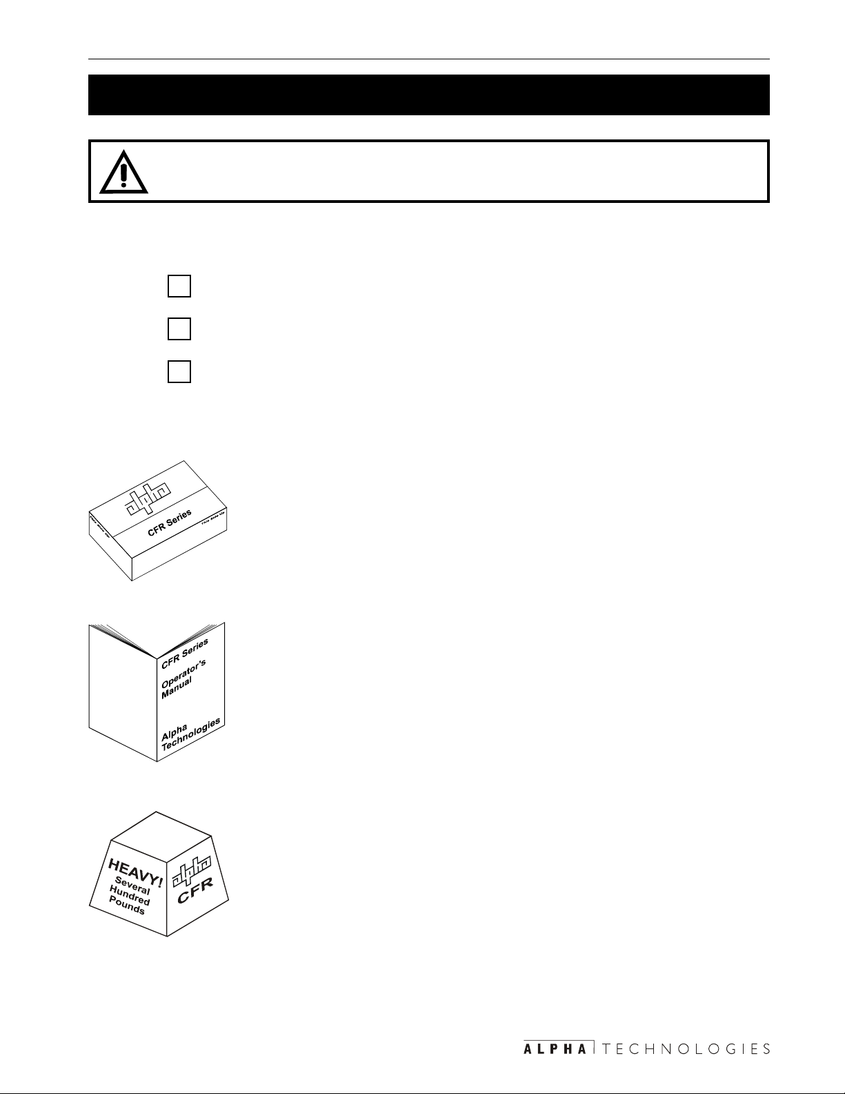
1.2 Unpacking and Inspection Checklist
TIP: If items are missing or damaged, contact Alpha and the shipping company at
once. Most shippers have a short claim period.
Carefully remove the unit from its shipping container . Inspect it for damage and make sure the
following items are included:
One CFR series UPS.
One operator’s manual.
Any ordered options.
Save The Original Shipping Container
If you should have to return the unit for servicing, pack it in the original
shipping container. Alpha is not responsible for damage caused by the
improper packaging of returned units.
Read This Manual
Before installation, become familiar with your unit by reviewing the procedures and drawings in this manual. If you have any questions about safe
installation, operation or maintenance, contact Alpha’s customer service
department.
Transportation And Site Planning
The weight of the unit and optional battery packs can be as much as
several hundred lbs/kg. A safe means of transportation to the site, lifting
the cabinet into position and proper floor support must be devised.
Page 10

1 Introduction
4
1.2 Unpacking and Inspection Checklist (Continued)
Complete the following for your records
Serial # __________________________________
Options __________________________________
Purchase Date ____________________________
This CFR was purchased from
Dealer ___________________________________
City _____________________________________
State/Province_____________________________
Zip/Postal Code ___________________________
Country __________________________________
T elephone #_______________________________
Fax #____________________________________
E Mail ___________________________________
T o order parts or for technical information, cont act Alpha T echnologies customer service department directly at:
:setatSdetinU:setatSdetinU
:adanaC6741-034)406(
:setatSdetinU:setatSdetinU0632-746)063(
:setatSdetinU
:modgniKdetinU011224-9721-44+
:ynamreG:ynamreG
:ynamreG:ynamreG0-98897-2219-94+
:ynamreG
:ailartsuA0233-2279-2-16+
:tsaEelddiM57657-352-753+
For emergency technical support 7 days a week / 24 hours a day call:
USA: 1–800–863–3364
CANADA: 1–800–667–8743
Page 11
5 1 Introduction
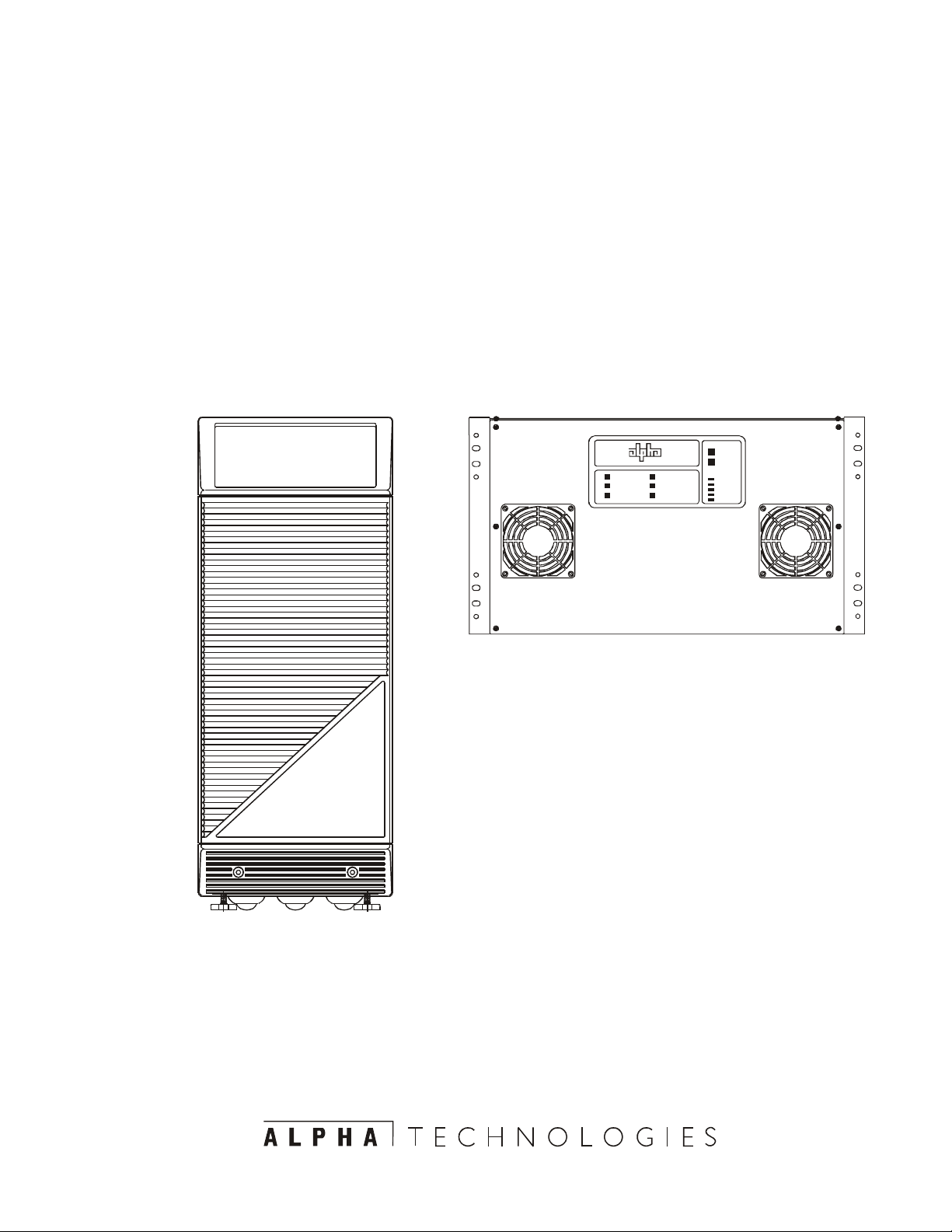
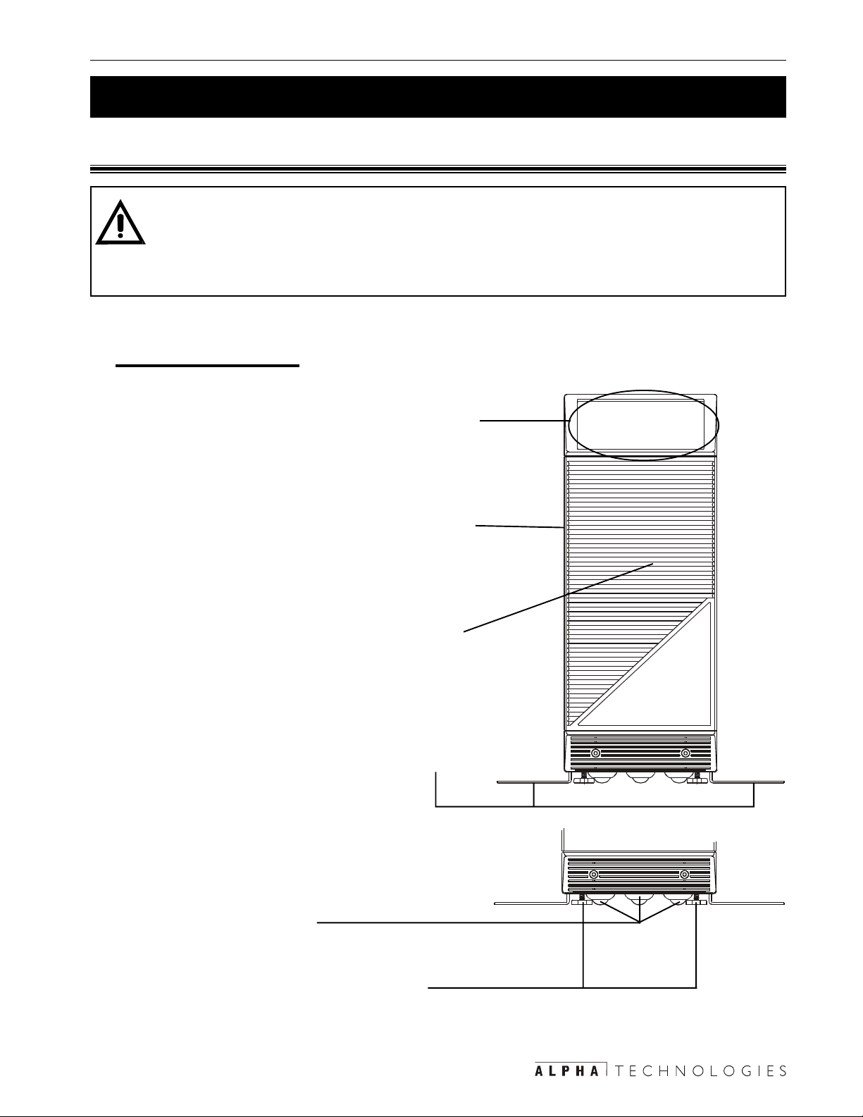
1.3 The Alpha CFR 3000 and 3000RM
1.3.1 Front Panel
TIP: Unless otherwise shown in this manual, the 3000 and 3000RM are identical and
operate the same way .
The major difference is the 3000RM does not have internal batteries. An Alpha Exter-
nal Battery Pack (EBP) must be connected (Section 2.4).
3000 Tower Mount
Display Panel
This is either the St andard Interface Display (SID)
(Section 3.5) or the optional Intelligent Interface
Device (IID) (manual #018–029–B0–001).
Cover
The cover can be removed to allow access to the
unit’s interior in order to change the batteries,
perform maintenance, etc. (Section 5.4).
Front Panel
The front panel can be removed to allow access
to the unit’s interior in order to change the batteries, perform maintenance, etc. (Section 5.4).
Seismic Brackets
These secure the unit to the floor if required by the
local codes. They are removable (Section 2.2).
Casters
These let you move the unit.
Feet
If you don’t secure the unit with the seismic
brackets, you can stop the unit from moving by
screwing these down.
Page 12
1 Introduction
6
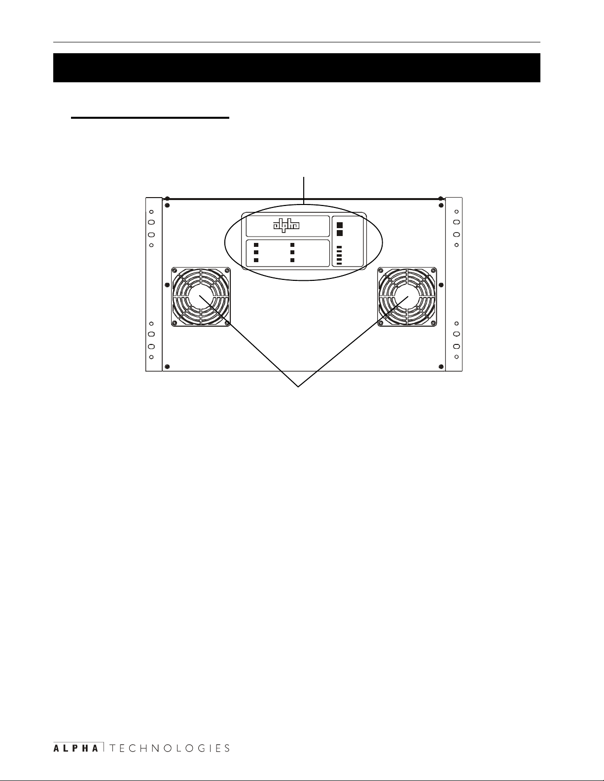
1.3 The Alpha CFR 3000 and 3000RM (Continued)
3000 Rack Mount (RM)
Display Panel
This is either the St andard Interface Display (SID) (Section 3.5) or the
optional Intelligent Interface Device (IID) (manual #018–029–B0–001).
ALARM
OFF
MANUAL
START
LINE PRESENT
LINE FAILURE
SERVICE
LOW BATTERY
WARNING
LOW BATTERY
SHUTDOWN
TEST
OUTPUT LOAD
OVERLOAD
100%
75%
50%
25%
Fans
These two fans cool the unit. They must not be blocked.
Page 13
7 1 Introduction
1.3 The Alpha CFR 3000 and 3000RM (Continued)
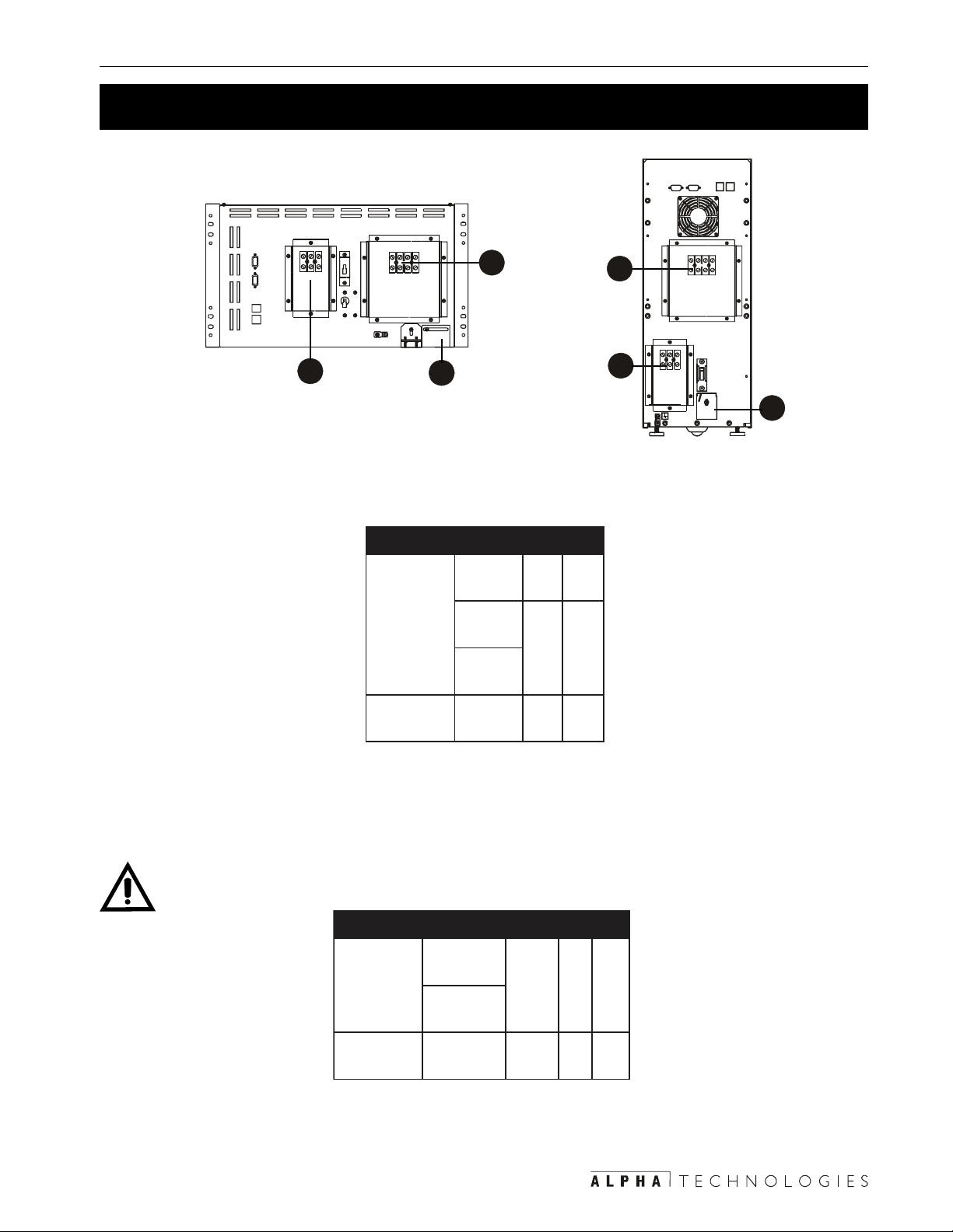
1.3.2 Rear Panel
3000RM
3000
Figure 1.1
Rear Panels
Fan (3000 Only)
This fan cools the unit. It must not be
blocked.
Output Receptacles
This is the unit’s output power connector . It
is factory configured to your specifica-
tions. See Section 2.3 for wiring informa-
tion.
Output Circuit Breaker
This resettable breaker provides addi-
tional protection to the load.
Page 14
1 Introduction
8
1.3 The Alpha CFR 3000 and 3000RM (Continued)
Input Circuit Breaker
This provides protection for the unit. It can
be used as an input power on/off switch.
AC Line Cord
This is a standard, grounded line cord.
Battery Circuit Breaker
This protects the unit’s inverter and DC
circuits and can be used as a battery
power on/off switch.
TIP: It should be switched off
whenever the unit is turned off for
more than a few hours or is being
serviced. Having this breaker on
can drain the battery .
External Ground Lug
This provides a single point ground
connection. Always follow your local
electrical code for correct grounding.
This connector grounds the external EBP
battery packs to the unit.
External Battery Connector
It accepts a standard plug from either
Alpha's EBP series battery pack or a
custom battery source (Section 2.4).
Page 15
9 1 Introduction
1.3 The Alpha CFR 3000 and 3000RM (Continued)
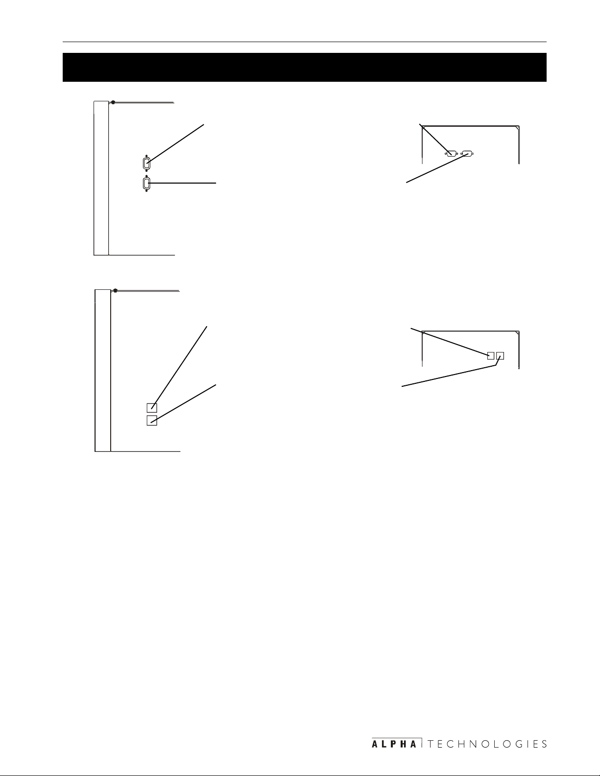
RS-232 Connector
This DB–9 port is the RS–232 connection
(Section 2.6).
LAN Interface Connector
This DB–9 port provides dry contact
status monitoring and output shutdown
capability via LAN communication (Sec-
tion 2.7).
External I2D
An external IID plugs into this connector
for remote control and monitoring.
External Alarm Connector
This RJ–45 connector provides line
failure and low battery warning informa-
tion and allows the connection of an
emergency shutdown switch with Form–
C contacts (Section 2.5).
Page 16

10
Section 2
Installation
This section shows you how to install
and connect the Alpha CFR 3000 and
3000RM UPS’s:
• A pre-installation checklist (Section 2.1).
• How to unpack and install the unit (Section 2.2).
• How to connect the unit to the loads, the batteries and the line (Section 2.3).
• How to connect the external battery packs (Section 2.4).
• How to connect the external alarm port (Section
2.5).
• How to connect the RS–232 communications port
(Section 2.6)
• How to connect the LAN port (Section 2.7).
• How to prevent the UPS from being overloaded
(Section 2.8)
Page 17

11 2 Installation
2.1 Pre–Installation Checklist
2.1.1 Site Preparation
Install the unit upright in a dry, well-ventilated, dust free environment. There must be at least
6 inches (152 mm) between the unit and the wall(s) for cooling and access to the front and
rear panels. Do not place the unit next to air conditioning or heating thermostats.
Do not connect the unit to line conditioning equipment. This can cause improper operation
of both the unit and the equipment.
Do not connect equipment that produces electrical noise such as motors, relay control
circuits, copiers or laser printers to the same circuit as quieter or more sensitive devices.
The unit cannot fully protect this type of equipment when noisy devices are connected.
Electrically noisy equipment should be connected to a dedicated unit.
Place a warning label on the electrical panel so emergency personnel know a UPS is in the
building. Label the service panel(s) to identify the circuit(s) supplying and being supplied by
the unit.
2.1.2 Grounding & Utility Line
All wiring should be done only by qualified personnel and comply with the local electrical
code.
The unit’s input and output voltage is factory configured to your specifications. If you need to
change either one or both, see Section 5.5, “Configuring the Input/Output Voltage.”
If required, install a hardwired ground. Since many older facilities have improper grounding,
a qualified electrician should inspect both the wiring and the grounding before installation.
Measure the line voltage at the main electrical panel. Compare that reading with the input
rating of the unit as listed on the nameplate label on the back panel:
• 240 VAC units: the voltage must be between 216 VAC and 252 VAC.
• 230 VAC units: the voltage must be between 207 VAC and 242 VAC.
• 208 VAC units: the voltage must be between 188 VAC and 216 VAC.
• 120 VAC units: the voltage must be between 110 VAC and 125 VAC.
Also see Section 2.8, “Transformer Output Load Sharing.” For information about
reconfiguring the unit’s input or output voltage , see Section 5.5, “Configuring the Input/
Output Voltage.”
Page 18

2 Installation 12
2.1 Pre–Installation Checklist (Continued)
The unit should be wired to dedicated circuit equipped with a properly sized circuit breaker.
The breaker’s size is the unit’s maximum input current (as given in the specifications) plus
25%.
For example if the unit draws 32.0 Amps of current at 208 VAC, adding 25% the input
current becomes 40.0 Amps. A 40 Amp circuit breaker would be OK. Always follow the
local electrical code when installing or sizing circuit breakers.
2.1.3 Standby Generator
The unit has frequency sense circuits for operation with most standby generators. Use a
generator equipped with electronic speed and voltage controls since the unstable frequencies created by a mechanical governor can make the unit run continuously in line failure
mode, draining the batteries.
Before installation see that the generator’s output voltage meets the unit’s input voltage
requirements as shown on both nameplates. A 240 VAC unit must be attached to a 240
VAC generator.
Page 19
13 2 Installation
2.2 Installing the Unit
2.2.1: CFR 3000
TIP: The seismic brackets can be removed if they are not required by the local code or
you are not in an earthquake zone (See
Tools and Materials Required:
• Fork lift or other means of transporting heavy objects (up to 288 lbs./131 kg).
• Screwdriver or power screwdriver with a Philips bit.
•15/16 inch socket wrench.
5
).
Procedure:
The unit is shipped attached to a pallet. Use a forklift to transport the unit and pallet to the
1
installation site.
Remove the packing from around the unit. Unbolt the unit from the pallet.
2
Slide the unit off the pallet as per the included instruction sheet (017–098–C3). Move the
3
unit to its final position.
If the seismic brackets are used:
4
The drawing below looks down unto the brackets and the floor:
0.562 inch diameter for mounting 0.5 inch anchor bolts.
0.781 inch diameter for mounting heavy duty anchor bolts
(Hilti #665927 (HSL M12/25)).
Mark the position on the floor where the unit will be secured by using the bracket as a template. Drill holes and secure using the appropriate anchor bolts.
Page 20
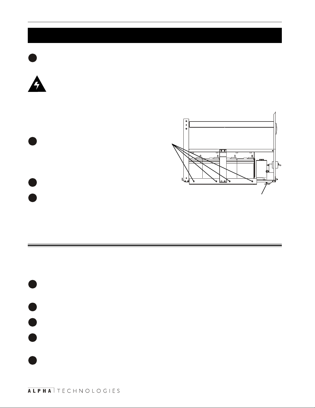
2 Installation 14
2.2 Installing the Unit (Continued)
If the brackets are not needed, remove the cover and the front panel as described in Sec-
5
tion 5.4, Step 1, “Remove the Front Panel and the Cover .”
DANGER:
1) There are dangerous voltages inside the unit when the cover is removed.
2) When removing or attaching the cover , do not let it touch the battery terminals, battery
wires or other internal components.
Remove the seismic brackets by unbolting the four
6
bolts attaching them to the unit.
Reattach the cover and the front panel.
7
T o stop the unit from moving, screw down the feet until they are solid against the floor .
8
Installation finished
2.2.2: CFR 3000RM
Tip: The unit is shipped so that it will fit in a 19 inch rack. To fit in a 23 inch rack, reverse the
position of the mounting brackets.
Procedure:
The unit is shipped attached to a pallet. Use a forklift to transport the unit and pallet to the
1
installation site.
Remove the packing from around the unit. Unbolt the unit from the pallet.
2
Move the unit to the rack.
3
Mount it in the rack. The mounting screws are not provided by Alpha. Use the screws speci-
4
fied for your rack.
Mount an Alpha external battery pack (Section 2.4).
5
Installation finished
Page 21
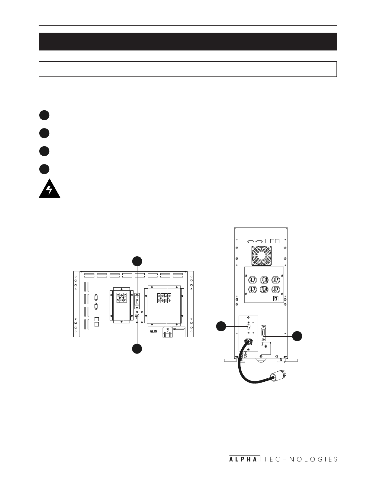
15 2 Installation
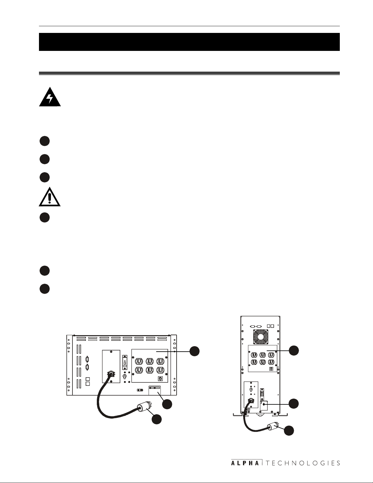
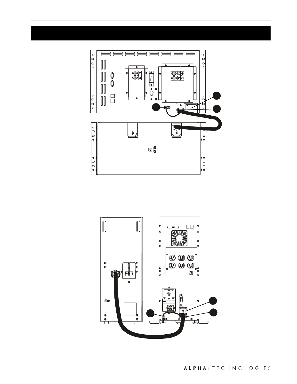
2.3 Connecting the Unit
2.3.1: Plug and Connector
Danger: All wiring must meet the local electrical code. Mark all circuit breakers supply-
ing power to the unit. Connect a dedicated ground wire to the external ground lug if the
building ground is inadequate.
Procedure:
Switch off the utility circuit breaker supplying power to the unit.
1
Plug the unit’s AC line cord into the receptacle.
2
If used, plug in an external battery pack (Section 2.4).
3
TIP: The rackmount unit has no internal batteries. It uses an external battery pack.
Switch on the utility circuit breaker supplying power to the unit. St art and test the unit with no
4
loads connected (Section 3.3).
• If it passes go to the next step.
• If it doesn’t do troubleshooting (Sections 3.4, 5.2).
Turn of f the unit (Section 3.2).
5
Connect the loads. The loads must be turned off before connection.
6
Connection Finished
6
6
3
2
Figure 2.1
Connecting the Unit (Plug and Connector)
3
2
Page 22

2 Installation 16
2.3 Connecting the Unit (Continued)
2.3.2: Terminal Block
Danger: All wiring must meet the local electrical code. Mark all circuit breakers supply-
ing power to the unit. Connect a dedicated ground wire to the external ground lug if the
building ground is inadequate.
Procedure:
Switch off the utility circuit breaker supplying power to the unit.
1
Connect the line to the terminal block as given in Figure 2.3.
2
• For 120 VAC units use 12 AWG (3.3 mm2).
• For 208/230/240 VAC units use 14 AWG (2.0 mm2).
• Torque to 35 Inch–Pounds (4.0 Nm).
• Switch on the utility circuit breaker supplying power to the unit. Make sure the unit has
been wired correctly by measuring the voltages at the terminal block. Switch off the circuit
breaker.
If used, plug in an external battery pack (Section 2.4).
3
TIP: The rackmount unit has no internal batteries. It uses an external battery pack.
Switch on the utility circuit breaker supplying power to the unit. St art and test the unit with no
4
loads connected (Section 3.3).
• If it passes go to the next step.
• If it doesn’t do troubleshooting (Sections 3.4, 5.2).
Switch off the unit (Section 3.2).
5
Connect the loads to the terminal block as shown in Figure 2.4. See 2 for the recom-
6
mended wire gauges and torques.
Connection Finished
Page 23
17 2 Installation
2.3 Connecting the Unit (Continued)
6
2
Connecting the Unit (T erminal Block)
3
Figure 2.2
ycneuqerFycneuqerF
ycneuqerFycneuqerF *egatloV*egatloV
ycneuqerF
zH06zH06
zH06zH06
zH06
zH05zH05
zH05zH05
zH05
*egatloV*egatloV
*egatloV
021021
021021
021
LLLLLNNNNN
CAV
802802
802802
802
CAV
042042
042042
042
CAV
032032
032032
032
CAV
1L1L1L1L1L2L2L2L2L2L
LLLLLNNNNN
6
2
3
* Caution: Refer to the voltage and frequency ratings for the unit as shown on the nameplate.
Figure 2.3
Input T erminal Block Wiring
TIP: Over current protection for the AC output circuit must be provided when the unit is
installed.
ycneuqerFycneuqerF
ycneuqerFycneuqerF *egatloV*egatloV
ycneuqerF
zH06zH06
zH06zH06
zH06
zH05zH05
zH05zH05CAV032CAV032
zH05
* Caution: Refer to the voltage and frequency ratings for the unit as shown on the nameplate.
*egatloV*egatloV
*egatloV
802/021802/021
802/021802/021
802/021
CAV
042/021042/021
042/021042/021
042/021
CAV
CAV032CAV032
CAV032
1L1L1L1L1LNNNNN2L2L2L2L2L
toNtoN
toNtoN
toN
NNNNNLLLLL
desU
Figure 2.4
Output Terminal Block Wiring
Page 24
2 Installation 18
2.4 Connecting the External Battery Pack
DANGER: There are hazardous voltages inside the battery packs. Use extreme cau-
tion. For more information on battery handling, see the safety instructions in the front of
this manual.
CAUTION:
1) Verify the p ack’s polarity and voltage at the connector before attaching the cable to
the unit.
2) When a pack or batteries have been in storage for more than 6 months, they should
be recharged for at least 24 hours and then thoroughly tested with a load before installation. If after charging, a battery’s voltage varies more than 0.3 VDC from the others, do
not use it.
Tools and Materials Required:
• DC voltmeter.
• Phillips screwdriver.
Procedure:
Verify the battery circuit breaker is switched of f. Keep it off until after the unit has been
1
started with line power .
Loosen the cover plate and slide it up to expose the connector (Figures 2.5, 2.6)
2
Verify the correct DC volt age and polarity at the battery pack’s connector . It should be
3
between 48 to 53 VDC.
TIP: Wrong voltages or polarities could damage the unit or the battery pack.
Connect the pack’s ground wire to the unit’s ground connection.
4
Connect the pack’s connector to the unit’s battery connector .
5
.
Battery Pack Connection Finished
Page 25
19 2 Installation
2.4 Connecting the External Battery Pack (Continued)
2
4
Figure 2.5
Connecting an External Battery Pack to the 3000RM
5
4
Figure 2.6
Connecting an External Battery Pack to the 3000
2
5
Page 26
2 Installation 20
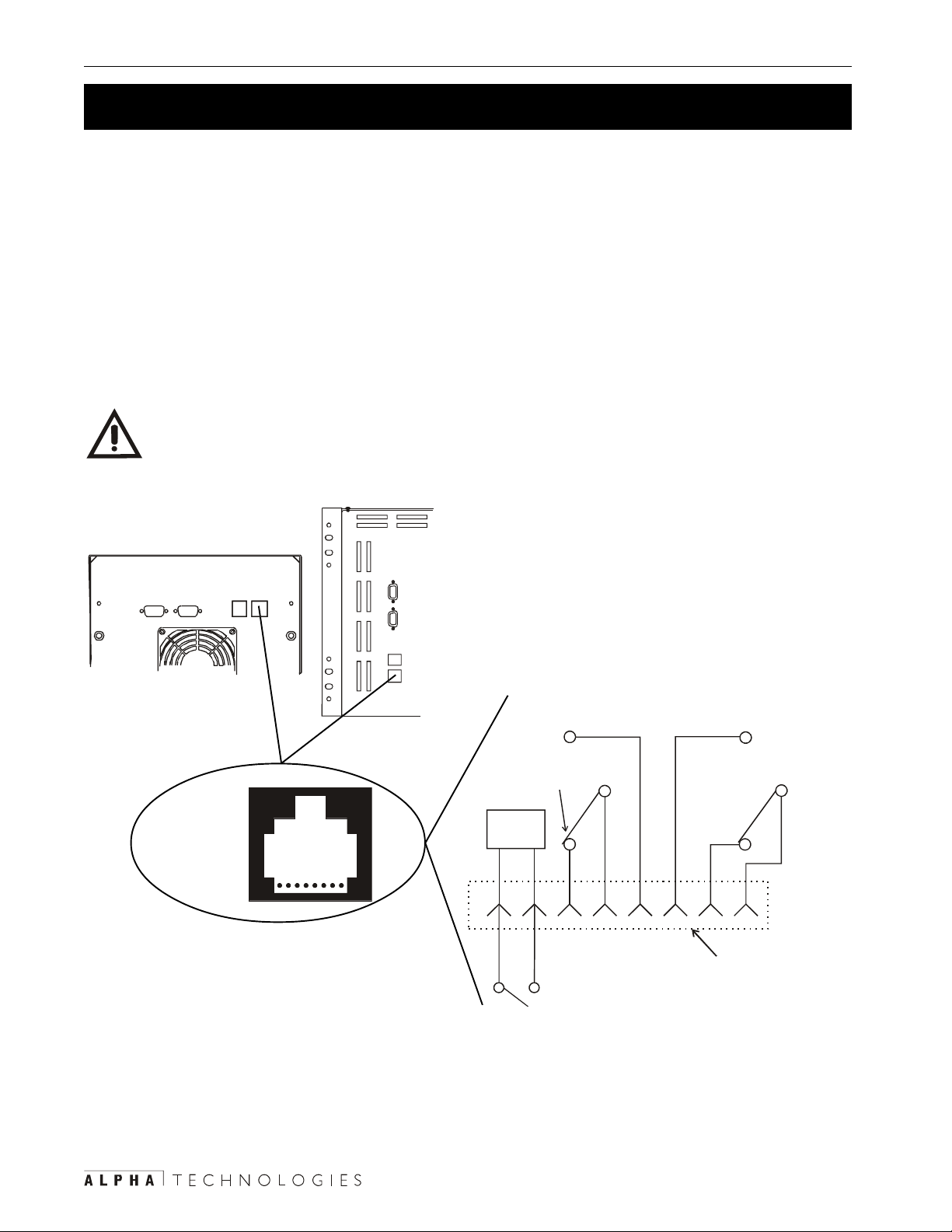
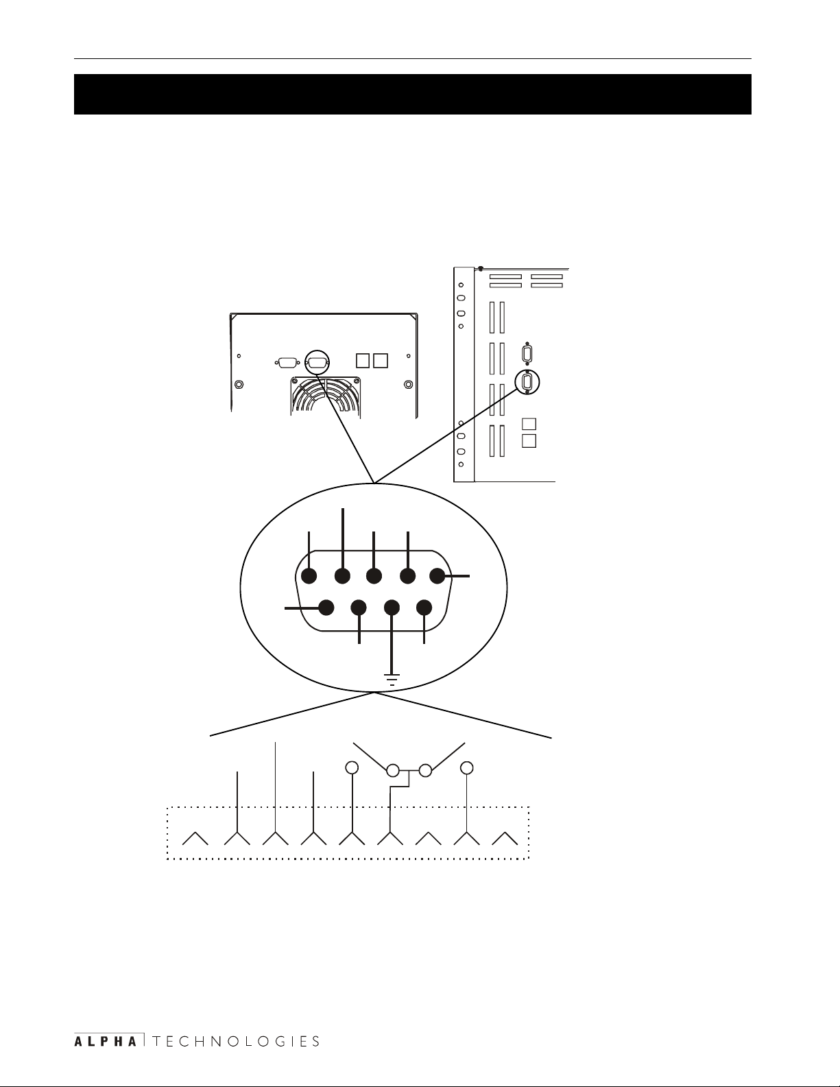
2.5 Connecting the External Alarm Port
An external alarm panel can be connected to the external alarm port (Figure 2.7). The port’s
contacts are rated at 30 VDC at 1 Amp.
An Emergency Power Off (EPO) switch is created by wiring a switch to Pins 7 and 8. This feature must be ordered from the factory so the unit can be configured to operate with this switch.
• The switch must be a SPST, N.O. type and be electrically isolated (up to 1500 VAC
isolation is recommended). The connecting cable can be twisted or shielded wire not
more than 100 ft. long.
• The contacts must be shorted for at least 1.5 seconds with unit shutdown about 2 seconds
after the shorting starts.
CAUTION: The EPO switch does not disconnect the utility line. Switch off the circuit
breaker providing line power to the unit.
RJ-45
Connector
(8-Pin Type)
N.O. Low
Battery W arn in g
N.C.
Battery OK
EPO
Circuit
18
87654321
Optional
N.O. EPO Switch
Figure 2.7
Wiring the External Alarm Port
N.O. Line
Failure
N.C. Line
Present
UPS Internal
UPS External
Contact Rating:
30 VDC @ 1 Amp
Page 27
21 2 Installation
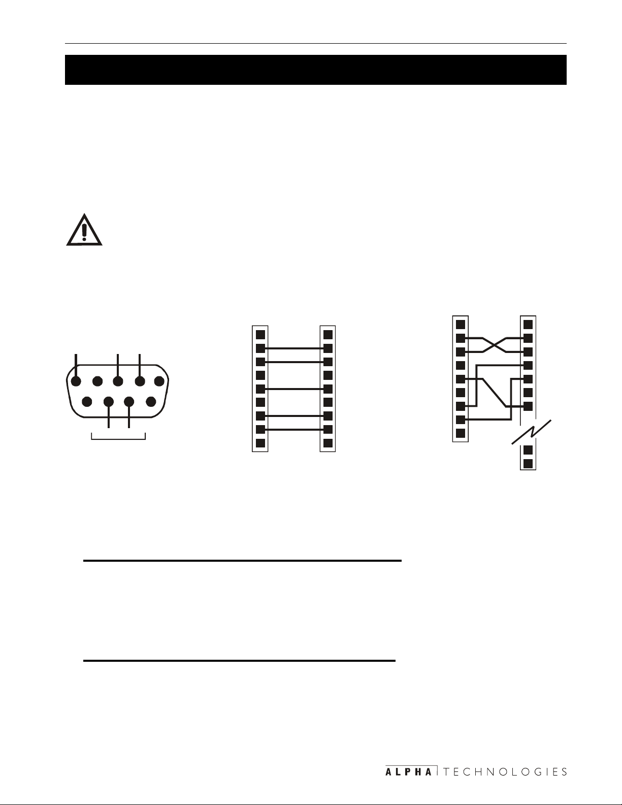
2.6 Connecting the RS–232 Port
The unit can be remotely setup, monitored, and tested by connecting the unit’s DB–9 connector
to a computer’s serial port (Figure 2.8) or communication via a LAN with an optional SNMP
agent. Windows HyperT erminal or any other terminal emulation program is used to communicate with the unit. Section 4 gives more information.
The DB–9 port is a standard feature, but its configuration is different depending upon if a SID or
IID display panel is installed on the unit.
TIPS:
1) The cable must be less than 50 ft (15m). long and it must be shielded to meet EMI
requirements.
2) The RS–232 is not isolated. Signal ground is directly connected to the internal logic
ground. Contact Alpha if the external battery connector must be referenced to positive
ground instead of negative ground (the factory default).
1
TXD 2
RXD 3
4
GND 5
6
RTS 7
CTS 8
9
UNIT RS-232
SERIAL CONNECTOR
(9-PIN FEMALE)
TXDRXDGND
345
789
CTS RTS
FOR USE WITH II D
EQUIPPED UNITS
1
TXD 2
RXD 3
4
12
6
GND 5
6
RTS 7
CTS 8
9
UNIT RS-232
SERIAL CO NNECTOR
(9-PIN FEMALE)
1
2 RXD
3 TXD
4
5 GND
6
7 RTS
8 CTS
9
9-PIN IBM PC
SERIAL PORT
Figure 2.8
RS–232 Wiring Diagrams
Connecting Units With an SID Display Panel:
• It uses a basic 3–wire line with software handshaking (XON / XOFF).
• Figure 2.8 shows how to connect the RS–232 port to a standard PC serial port.
• The parameters are: 1200 baud, 8 data bits, no parity, 1 stop bit.
1
2 TXD
3 RXD
4 RTS
5 CTS
6
7 GND
24
25
25-PIN IBM PC
SERIAL PORT
Connecting Units With an IID Display Panel:
• The IID RS–232 port uses a nonstandard cable with RTS/CTS signal straight through
and RX/TX signals reversed.
• The baud rate is operator-configurable.
• For further information on IID RS–232 applications refer to “Information Management
Using the Intelligent Interface Device” manual (Alpha P/N # 018–029–B0–001).
Page 28
2 Installation 22
2.7 Connecting the LAN Port
The unit can be remotely monitored and shutdown with the unit’s DB–9 LAN port (Figure 2.9).
Two dry cont acts provide line failure and low battery information. A connection to the unit’s mi-
croprocessor shuts down the unit’s output. The shut down delay, duration and recovery is controlled via RS–232 commands (Section 4.5).
9
Common
+12 VDC
5 mA (Max)
Not
Connected
GND
Low
Battery
Output
Shutdown
Connected
+12 VDC
5 mA (Max)
N.O. Low
Battery
Not
Line
Fail
6789
Output
Shutdown
Common
12345
N.O. Line
Failure
Not
Connected
87654321
Figure 2.9
Wiring the LAN Port
UPS Internal
UPS External
Page 29

23 2 Installation
2.8 Transformer Output Load Sharing
2.8.1: Transformer Output
The units have a single phase output. They do NOT have three phase characteristics.
Figure 2.10 shows the voltages between L1, L2 and N for 120/208/240 units and between L and
N for 230 V AC units
60 Hz Units
TRANSFORMER
FERRO
32 VAC
120 VAC
88 VAC
240 VAC
TRANSFORMER
208 VAC
120 or 88 VAC
50 Hz Units
FERRO
L
120 VAC
L1
NEUTRAL
120 VAC
240 or 208 VAC
230 VAC
N
Figure 2.10
Transformer Output
2.8.2: Load Sharing
The total current drawn from each winding must not exceed that winding’s maximum output
current rating (Figure 2.1 1). For 60 Hz units, where possible, connect 120 V AC loads to L1.
zH060003RFCzH060003RFC
1L1L1L1L1LspmA0.52spmA0.52
zH060003RFCzH060003RFC zH050003RFCzH050003RFC
zH060003RFC
spmA0.52spmA0.52LLLLLspmA0.31spmA0.31
spmA0.52
zH050003RFCzH050003RFC
zH050003RFC
spmA0.31spmA0.31
spmA0.31
2L2L2L2L2LspmA4.41spmA4.41
spmA4.41spmA4.41----------------------
spmA4.41
----------------------
-----------
Figure 2.1 1
Transformer Output Current Ratings
Since loads are shared between windings, you can exceed a winding’s output without exceeding the unit’s maximum current output. There are two ways to calculate the current drawn by the
loads; measuring or displaying the output current.
Page 30

2 Installation 24
2.8 Transformer Output Load Sharing (Continued)
2.8.2.1: Measuring the Output Current
This uses a clip-on current probe (Figure 2.12 for 240 V AC, Figure 2.13 for 208 V AC and Figure 2.14 for 230 V AC).
For 120/208/240 V AC units the total current drawn from Winding 1 is the sum of the current s A,
B and C where:
• A is the total current drawn by all of the 120V loads connected to the receptacle.
• B is the total current drawn by all of the 240V loads connected to the receptacle.
• C is the total current drawn from the L1 side of the terminal block.
The total of these currents must not exceed the rated output current for the L1 winding.
For the L2 winding of the transformer , measure the currents at points B and D where:
• B is the total current drawn by all of the 240V loads connected to the receptacle.
• D is the total current drawn from the L2 side of the terminal block.
The total of these currents must not exceed the rated output current for the L2 winding.
D
Output Current 2
Winding 2
Output Current 1
Winding 1
Output Current L1
240 VAC
Receptacle
120 VAC
Receptacle
A
B
Output
Terminal Block
L2
N
L1
120
VAC
240 VAC
120
VAC
C
Figure 2.12
120/120/240 V AC Current Measurement Points
D
Output Current 2
Winding 2
Output Current 1
Winding 1
Output Current L1
208 VAC
Receptacle
120 VAC
Receptacle
A
B
Output
Termin al Block
L2
N
L1
Not Used
120
VAC
C
208 V A C
Figure 2.13
120/208 V AC Current Measurement Points
Page 31

25 2 Installation
2.8 Transformer Output Load Sharing (Continued)
The total outp u t cu r re n t fo r
230 VAC units is measured at A.
A
230 VAC
Receptacle
Output
Termin al Block
Figure 2.14
230 V AC Current Measurement Point
2.8.2.2: Displaying the Output Current
TIP: When using the display panels, you must calculate L1’s current as described
below.
Using the SID Display Panel:
L
230 VAC
N
The current is displayed via RS–232 as Output Current 1 and Output Current 2 (Section
4.4.3).
Use the menu to display Output Current 1 and Output Current 2.
1
The current in Winding 1 (Output Current L1) is the sum of Output Currents 1 and 2.
2
The current in Winding 2 is Output Current 2.
3
The Overload LED will flash if the total current in either winding exceeds its maximum
rating or if the total output in V A or Watts exceeds the unit’ s maximum output.
Using the IID Display Panel:
Use the menu to display Output Current 1 and Output Current 2.
1
The current in Winding 1 (Output Current L1) is the sum of Output Currents 1 and 2.
2
The current in Winding 2 is Output Current 2.
3
Page 32

26
Section 3
Operation
This section shows you how to operate
the Alpha CFR 3000 and 3000RM UPS’s:
• How to turn the unit on and off (Sections 3.1, 3.2).
• How to start the unit’s self test (Section 3.3).
• How to troubleshoot the unit with the SID
(Section 3.4).
• How to use the Standard Interface Device (SID)
(Section 3.5).
Page 33

27 3 Operation
3.1 Turning On the Unit
WARNINGS:
1) The unit runs warm to the touch. During the first few weeks of operation, a brand new
unit may give off an odor caused by the burning of the lacquer finishing of the transformer . This is normal and is not toxic.
2) This unit generates electromagnetic radiation. Keep all sensitive magnetic media
such as floppy disks, recording tape, key cards, bank and credit cards away from it.
Procedure:
Switch off:
1
• All loads connected to the unit.
• The input and battery circuit breakers (Figure 3.1).
Switch on the circuit breaker on the utility panel supplying power to the unit.
2
Switch on the Input circuit breaker.
3
The display panel’s Line Present LED turns on to show the unit is running on line power .
TIP: There is a delay of 5 to 15 seconds before the unit energizes. If it has an SID, the T est
LED flashes. If the unit does not turn on, perform troubleshooting (Sections 3.4, 5.2). Do not
perform a cold start.
Switch on the Battery circuit breaker .
4
Do a self test (Section 3.3).
5
One at a time, turn on the loads.
6
As each load is turned on, look at the load indicator on the control panel to make sure the
unit is not overloaded (Section 3.5, “Output Load”).
Start Up Finished
Page 34

3 Operation
28
3.1 Turning On the Unit (Continued)
1
4
1
3
3
4
Figure 3.1
Turning the Unit On
Cold Start Procedure
This starts the unit with battery power when line power is unavailable or unqualified. Backup
battery power is provided to the loads.
Switch on the Battery circuit breaker .
1
For units with the:
2
• SID display panel, press the Manual S tart button. The unit’s alarm beeps every 20
seconds, indicating it is running on battery power.
• IID display panel, press the T est button.
Cold Start Finished
Page 35
29 3 Operation
3.2 Turning Off the Unit
The emergency shutdown procedure is on the inside rear cover .
Procedure:
One at time, turn off the loads.
1
Switch off the Battery circuit breaker .
2
Switch off the Input circuit breaker .
3
If servicing the unit, switch off the utility circuit breaker supplying the unit.
4
DANGER: During servicing put a warning note on the circuit breaker supplying the unit.
Shutdown Finished
2
3
2
3
Figure 3.2
Turning the Unit Off
Page 36

3 Operation
30
3.3 Testing the Unit
The self test confirms the unit can switch from line to backup battery power and back without
interrupting power to the loads. It takes about one minute to run.
Before starting:
• The Battery circuit breaker must be on.
• The control panel’s Line Present LED must be on.
Procedure:
Press the Manual Start button down for 5
1
seconds.
ALARM
During the test, the T est, Line Present and
Line Failure LEDs are on for about one
minute.
If a fault is found, the unit defaults to Line
2
Present operation without interrupting the
output. The Service LED turns on. Do
troubleshooting (Sections 3.4, 5.2).
LINE PRESENT
LINE FAILURE
SERVICE
LOW BATTERY
WARNING
LOW BATTERY
SHUTDOWN
TEST
OFF
MANUAL
START
OUTPUT LOAD
OVERLOAD
100%
75%
50%
25%
TIP: The unit cannot provide backup battery
power when the Service LED is on.
Self Test Finished
Page 37

31 3 Operation
3.4 Troubleshooting With the SID
The SID’s Output Load LEDs have two functions:
• When the unit is operating normally, it serves to show the unit’s output loading.
• When the Service LED is on, the load LEDs are turned into a fault indicator for as long as
the Alarm Off button is pushed and held down.
TIP: See Section 5.2 for more troubleshooting information.
Procedure:
When the Service LED is on, press and hold
1
down the Alarm Of f button.
OUTPUT LOAD
The Output Load LEDs show a fault code.
2
Refer to Figure 3.3 for the fault descriptions.
Fix the fault.
3
T o clear some faults from the p anel, you may
4
LINE PRESENT
LINE FAILURE
SERVICE
LOW BATTE RY
WARNING
LOW BATTE RY
SHUTDOWN
TEST
have to restart the unit. For others, the unit
automatically resets itself.
T roubleshooting Finished
TIP: If the line present LED flashes, the utility line is unqualified and the unit will not start.
DELDEL
DELDEL gnihsalFroNOgnihsalFroNO
DEL
daolrevOdaolrevO
daolrevOdaolrevO
daolrevO
daolrevOdaolrevO
daolrevOdaolrevO
daolrevO
%001%001
%001%001
%001
%001%001
%001%001
%001
%57%57
%57%57
%57
%57%57
%57%57
%57
%05%05
%05%05
%05
%05%05
%05%05
%05
%52%52
%52%52
%52
%52%52
%52%52
%52
* After fixing the malfunction, these are cleared from the display panel by shutting down and restarting the unit.
** After fixing the malfunction, the unit automatically returns to Line Present mode, clearing the malfunction from the panel.
NONONONONO
gnihsalFgnihsalF
gnihsalFgnihsalF
gnihsalF
NONONONONO
gnihsalFgnihsalF
gnihsalFgnihsalF
gnihsalF
NONONONONO
gnihsalFgnihsalF
gnihsalFgnihsalF
gnihsalF
NONONONONO
gnihsalFgnihsalF
gnihsalFgnihsalF
gnihsalF
NONONONONO
gnihsalFgnihsalF
gnihsalFgnihsalF
gnihsalF
gnihsalFroNOgnihsalFroNO noitcnuflaMnoitcnuflaM
gnihsalFroNO
noitcnuflaMnoitcnuflaM noitcAnoitcA
noitcnuflaM
.evitcaytivitisneswolrotcetedtsaF.seigolonhceTahplAtcatnoC
.denifedtoN.tinusihtnidesutoN
.erutarepmettneibmahgiH.gnikrowerasnafehtfieeS
.tluafLLP.seigolonhceTahplAtcatnoC
.tiucrictrohsegatlovtuptuO*.detiucrictrohstonsidaolehteeS
.hgihegatlovtuptuO*.seigolonhceTahplAtcatnoC
.eruliafMORPEEdraobrewoP
.eruliafliarrewoProTLFWHdraobrewoP
.tluafyrettabroegatlovrevoyrettaB
.tsetflesdeliaftinU**.yrettabehtkcehC
noitcAnoitcA
noitcA
esehtxiftonnacrotarepoehT
tcatnocdluohsdnasnoitcnuflam
*.ecnotaseigolonhceTahplA
**.no
sirekaerbtiucricyrettabehttahteeS
ALARM
OFF
MANUAL
START
OVERLOAD
100%
75%
50%
25%
Figure 3.3
Fault Chart
Page 38

3 Operation
32
3.5 Controlling the Unit with the Standard Interface Device (SID)
The Standard Interface Device (SID) display p anel (Figure 3.4) shows vital operating parameters and starts the self test. It has two push buttons, five LEDs showing the power drawn by the
loads and six LEDs showing the unit’s operating status.
ALARM
OFF
MANUAL
START
LINE PRESENT
LINE FAILURE
SERVICE
LOW BATTE RY
WARNING
LOW BATTE RY
SHUTDOWN
TEST
OUTPUT LOAD
OVERLOAD
100%
75%
50%
25%
Figure 3.4
Standard Interface Device Display Panel
LEDs
Line Present
This green LED is:
• On when the unit is running on line power.
• Off when there is no line power .
• Flashing when the line is present but unqualified.
Line Failure
This yellow LED is on when:
• The line voltage is greater than +10 % or less than –20% of nominal voltage.
• The line frequency is outside of ± 3% of the nominal frequency.
• The unit is providing backup battery power to the loads.
TIP: Also see Low Battery W arning and Low Battery Shutdown.
Service
This red LED shows the unit has a malfunction. Press and hold down the Alarm Off switch
and note which Output Load LEDs turns on or flashes (Section 3.4).
Low Battery W arning
This red LED turns on when the battery voltage is 8% below nominal. This shows the
batteries are almost discharged and a shutdown is pending. Y ou should begin a shutdown of the loads.
Page 39

33 3 Operation
3.5 Controlling the Unit with the Standard Interface Device (SID) (Continued)
Low Battery Shutdown
This red LED turns on when the battery voltage is 12% below nominal. The unit automatically shuts itself down and no longer provides power to the loads to prevent
overdischarge damage to the batteries.
Test
This yellow LED shows the unit is in self test mode (Section 3.3). If it fails the test, the
Service LED is on and the unit defaults to Line Present operation. Y ou should do troubleshooting as shown in Sections 3.4 or 5.2.
TIP: At start-up, this LED flashes for about 5 to 15 seconds.
Line Synchronization
If both the:
• Line Power
• Line Failure
LEDs are on, the unit is synchronizing its output with the input before starting Line
Present operation. This takes about 15 seconds.
Push Buttons
Alarm Off
This turns off most audible alarms. The alarm is off until another alarm occurs.
TIP: Some alarms, such as Line Failure, cannot be turned off and will continue to sound
every 20 seconds. If the Service LED is on, press and hold down the Alarm Off switch
and note which Output Load LEDs turns on or flashes (Section 3.4).
Manual Start
This starts the unit with battery power when line power is absent or unqualified.
It can also be used as a self test. If the Line Present LED is on, press it for 5 seconds.
This tests the inverter and batteries for one minute by providing backup battery power to
the loads, returning to line present mode when done.
Page 40

3 Operation
34
3.5 Controlling the Unit with the Standard Interface Device (SID) (Continued)
Output Load
These five green LED's show the unit’s loading as a percentage of its maximum output.
The Overload LED is on if:
• The output exceeds the unit’s maximum rating.
• The output exceeds either of the transformer output winding ratings (Section 2.8).
WARNING: Do not run the unit when it is overloaded. Damage to the unit, the inverter
or the batteries can result.
If the unit is in Output V oltage Shutdown mode the LED’s will continuously sequence until
the condition is cleared (Section 4.5.2, “Sub Menu #50: Set Output Shutdown Parameters”).
Page 41

35
Section 4
Communication
This section shows you how to control
the Alpha CFR 3000 and 3000RM UPS’s
with RS–232 commands:
• How to set up communications with Windows
HyperTerminal (Section 4.1).
• How to understand and use the opening menu
(Section 4.2).
• A description of the menu tree (Section 4.3).
• A description of the system, input and output and
battery parameters menus (Section 4.4).
• Descriptions of the user and maintenance parameters (Sections 4.5 and 4.6).
• How to connect and setup an external modem to
the unit (Section 4.7).
©
Windows is a copyright of the Microsoft corporation.
Page 42

4 Communication
36
4.1 RS–232 Set-Up
Wire the DB–9 connector as shown in Section 2.6, “Connecting the RS–232 Port.”
Windows HyperT erminal Connection
For this tutorial, Com 1 is used and the unit is called CFR.
Procedure
The path is Start/Programs/Accessories/
1
Communications/HyperTerminal.
Click on the Hypertrm.exe icon. The Con-
2
nection Description screen appears (Figure
4.1).
Enter a name and choose an icon for your
unit. Click OK.
The Connect T o screen appears (Figure 4.2).
3
Connect to COM 1. Click OK.
Figure 4.1
Connection Description Screen
Figure 4.2
Connect T o Screen
Page 43

37 4 Communication
4.1 RS–232 Set-Up (Continued)
The Com 1 Properties screen appears
4
(Figure 4.3). Fill out the fields as shown.
Click OK.
5
The CFR Screen appears.
6
Press Enter to go to the Open-
7
ing Menu (Figure 4.4).
The Opening Menu (Figure 4.5)
appears.
HyperT erminal Set-Up Finished
Figure 4.3
COM 1 Properties Screen
ALPHA TECHNOLOGIES–CFR
OPENING MENU
1 SYSTEM P ARAMETERS
2 INPUT P ARAMETERS
3 OUTPUT P ARAMETERS
4 BA TTERY P ARAMETERS
5 USER P ARAMETERS
6 -NOT AV AILABLE7 MAINTENANCE PARAMETERS
INPUT LINE: PRESENT
SERVICE2: SERVICE CODE 3
Figure 4.4
Opening Menu in CFR Screen
Page 44

4 Communication
38
4.2 Using the Opening Menu
The opening menu (Figure 4.5, also see Figure 4.4) is the top-level menu. It shows the line’s
status, displays if any alarms are present and gives access to the main menus. It is reached
from anywhere in the menu tree by pressing Enter.
The entire menu tree is given in Section 4.3. T ables describing the main and sub menus are
given in Sections 4.4 to 4.7.
Procedure:
T o access a particular main or sub menu, type in the number and press Enter. Pressing Enter
returns you to the opening menu screen.
Tips:
• The readings on the screen do not automatically update to reflect changes in the unit’s
status. To update it type in the number and press Enter.
• For many functions you need to enter a password. The factory set password is 1111.
• If you change the password (Item #58), make sure you record the new password in a safe
and easily accessible place.
• This program ignores the Backspace and Delete keys. If a command is typed in wrong,
press Enter and retype the command.
• “Service2: Service Code 3” is displayed in the alarm field every time the unit starts. This
is normal. To clear it, press Enter.
ALPHA TECHNOLOGIES–CFR
OPENING MENU
1 SYSTEM P ARAMETERS
2 INPUT P ARAMETERS
3 OUTPUT P ARAMETERS
Main Menus
4 BA TTERY P ARAMETERS
5 USER P ARAMETERS
6 -NOT A V AILABLE7 MAINTENANCE P ARAMETERS
Line
Status
Alarms (If any,
otherwise blank.
See Figures 4.6 to
4.9)
INPUT LINE: PRESENT
ALARMS:–
Figure 4.5
Opening Menu Screen
Page 45

39 4 Communication
4.2 Using the Opening Menu (Continued)
Figures 4.6 to 4.9 list the alarms, how they appear on the screen and what they mean.
smralAtupnIsmralAtupnI
smralAtupnIsmralAtupnI
smralAtupnI
emaNemaN
emaNemaN
emaN
neercSnoswohSneercSnoswohS
neercSnoswohSneercSnoswohS esuaCesuaC
neercSnoswohS
esuaCesuaC
esuaC
woLycneuqerFwoLycneuqerF
woLycneuqerFwoLycneuqerFOL_QERFOL_QERF
woLycneuqerF
iHycneuqerFiHycneuqerF
iHycneuqerFiHycneuqerFIH_QERFIH_QERF
iHycneuqerF
hctilGhctilG
hctilGhctilGHCTILGHCTILG
hctilG
ekipSekipS
ekipSekipSEKIPSEKIPS
ekipS
gaSgaS
gaSgaSGASGAS
gaS
egruSegruS
egruSegruSEGRUSEGRUS
egruS
tuonworBtuonworB
tuonworBtuonworBTUONWORBTUONWORB
tuonworB
egruSwolSegruSwolS
egruSwolSegruSwolSEGRUS_WOLSEGRUS_WOLS
egruSwolS
tuokcalBtuokcalB
tuokcalBtuokcalBTUOKCALBTUOKCALB
tuokcalB
emaNemaN
emaNemaN
emaN
yrettaBwoLyrettaBwoL
yrettaBwoLyrettaBwoL
yrettaBwoL
nwodtuhS
yrettaBwoLyrettaBwoL
yrettaBwoLyrettaBwoL
yrettaBwoL
gninraW
yrettaBhgiHyrettaBhgiH
yrettaBhgiHyrettaBhgiH
yrettaBhgiH
egatloV
fleSehtdeliaFfleSehtdeliaF
fleSehtdeliaFfleSehtdeliaF
fleSehtdeliaF
tseT
tluaFyrettaBtluaFyrettaB
tluaFyrettaBtluaFyrettaBTLF_TTABTLF_TTAB
tluaFyrettaB
OL_QERFOL_QERF
OL_QERF
IH_QERFIH_QERF
IH_QERF
HCTILGHCTILG
HCTILG
EKIPSEKIPS
EKIPS
GASGAS
GAS
EGRUSEGRUS
EGRUS
TUONWORBTUONWORB
TUONWORB
EGRUS_WOLSEGRUS_WOLS
EGRUS_WOLS
TUOKCALBTUOKCALB
TUOKCALB
.wolsiycneuqerftupniehT
.hgihsiycneuqerftupniehT
.hctilgastcetedtinuehT
.ekipsastcetedtinuehT
.gasastcetedtinuehT
.egrusastcetedtinuehT
.tuonworbastcetedtinuehT
.egruswolsastcetedtinuehT
sselsiegatlovSMRehtrosm21roftsolsiegatlovtupniehT
.sm001nahteromrofegatlovlanimoneht2/1naht
Figure 4.6
Input Alarms
smralAyrettaBsmralAyrettaB
smralAyrettaBsmralAyrettaB
smralAyrettaB
neercSnoswohSneercSnoswohS
neercSnoswohSneercSnoswohS esuaCesuaC
neercSnoswohS
NWDTHS_TTAB_WOLNWDTHS_TTAB_WOL
NWDTHS_TTAB_WOLNWDTHS_TTAB_WOL
NWDTHS_TTAB_WOL
NRAW_TTAB_OLNRAW_TTAB_OL
NRAW_TTAB_OLNRAW_TTAB_OL
NRAW_TTAB_OL
IH_TLOV_TTABIH_TLOV_TTAB
IH_TLOV_TTABIH_TLOV_TTAB
IH_TLOV_TTAB
TSET_FLES_LIAFTSET_FLES_LIAF
TSET_FLES_LIAFTSET_FLES_LIAF
TSET_FLES_LIAF
TLF_TTABTLF_TTAB
TLF_TTAB
.seirettabehtotegamad
.ffosirekaerbtiucric
esuaCesuaC
esuaC
egrahcsidrevotneverpotsdaolehtotrewoptuptuoffo
.sdaolehtnwodgnittuhstratsdluohsuoY
ehtrofebdluohstinahtrehgihsiegatlovregrahcehT
.seirettablanretxeotnoitcennocevitcefedro
.degamadtoneraseirettabehttahtdnano
tuhssahtinuehtdnalanimonwoleb%21siegatlovyrettabehT
ehtswohssihtdnalanimonwoleb%8siegatlovyrettabehT
.gnidnepsinwodtuhsadnadegrahcsidtsomlaeraseirettab
seirettabroregrahcytluafaybdesuacebnacsihT.seirettab
.tsetflesehtgniodelihwrewoptuptuoedivorptonnactinuehT
erasrekaerbtiucrictuptuodnayrettabehttahteesdluohsuoY
ybdesuacsisihtyllausU.seirettabehtegrahctonnactinuehT
yrettabehtrotinuehtotdetcennocgniebtonseirettabeht
Figure 4.7
Battery Alarms
Page 46

4 Communication
40
4.2 Using the Opening Menu (Continued)
smralAtuptuOsmralAtuptuO
smralAtuptuOsmralAtuptuO
smralAtuptuO
emaNemaN
emaNemaN
emaN
egatloVtuptuOegatloVtuptuO
egatloVtuptuOegatloVtuptuO
egatloVtuptuO
woL
neercSnoswohSneercSnoswohS
neercSnoswohSneercSnoswohS esuaCesuaC
neercSnoswohS
OL_TLOVOL_TLOV
OL_TLOVOL_TLOV
OL_TLOV
:ybdesuacebnacsihT
esuaCesuaC
esuaC
.tinuehtotdetcennocsdaolforebmun
ehtecudeR.tluaftinuasierehtrodedaolrevositinuehT
egatloVtuptuOegatloVtuptuO
egatloVtuptuOegatloVtuptuO
egatloVtuptuO
hgiH
rewoPtuptuOrewoPtuptuO
rewoPtuptuOrewoPtuptuO
rewoPtuptuO
daolrevO
AVtuptuOAVtuptuO
AVtuptuOAVtuptuO
AVtuptuO
daolrevO
tuptuOtuptuO
tuptuOtuptuO
tuptuO
tluaFegatlovrevO
trohStuptuOtrohStuptuO
trohStuptuOtrohStuptuO
trohStuptuO
tiucriC
IH_TLOVIH_TLOV
IH_TLOVIH_TLOV
IH_TLOV
DLVO_RWPDLVO_RWP
DLVO_RWPDLVO_RWP
DLVO_RWP
DLVO_AVDLVO_AV
DLVO_AVDLVO_AV
DLVO_AV
TLF_V_REVOTLF_V_REVO
TLF_V_REVOTLF_V_REVO
TLF_V_REVO
TCC_TROHSTCC_TROHS
TCC_TROHSTCC_TROHS
TCC_TROHS
.staeper
.ahplAybdecivrestievaH.evitcefedsitinuehT--
.degamadgniebmorfflestitcetorpotedom
.deunitnocsidsimralasihtlitnusdaol
.daolytluafarodaolehtfogniriw
.slavretniralugerritarewopswardtahttnempiuqefoeceipA--
mralaehtfieesdnatnempiuqetcepsusehttcennocsiD
nwodtuhsotniogyamtinuehT.dedaolrevosituptuos'tinuehT
tcennocsiD.gnitars'tinuehtsdeecxetnerructuptuoSMRehT
ehT.stiucriclortnoclanretnistininoitcnuflamasahtinuehT
.segatlovhgihmorfsdaolehttcetorpotffotuhssituptuo
reporpmiybdesuacebnacsihT.detiucric-trohssidaolA
Figure 4.8
Output Alarms
smralAecivreSdnalatnemnorivnEsmralAecivreSdnalatnemnorivnE
smralAecivreSdnalatnemnorivnEsmralAecivreSdnalatnemnorivnE
smralAecivreSdnalatnemnorivnE
emaNemaN
emaNemaN
emaN
lanretnIlanretnI
lanretnIlanretnI
lanretnI
hgiHerutarepmeT
kcoLdesahPkcoLdesahP
kcoLdesahPkcoLdesahP
kcoLdesahP
eruliaFpooL
erawtfoSorciMerawtfoSorciM
erawtfoSorciMerawtfoSorciM
erawtfoSorciM
teseR
erawdraHorciMerawdraHorciM
erawdraHorciMerawdraHorciM
erawdraHorciM
teseR
draoBrewoPdraoBrewoP
draoBrewoPdraoBrewoP
draoBrewoP
tluaFMORPEE
draoBrewoPdraoBrewoP
draoBrewoPdraoBrewoP
draoBrewoP
tluaFerawdraH
CDevitageNCDevitageN
CDevitageNCDevitageN
CDevitageN
liaFliaRylppuS
ycnegremEycnegremE
ycnegremEycnegremE
ycnegremE
ffOrewoP
neercSnoswohSneercSnoswohS
neercSnoswohSneercSnoswohS esuaCesuaC
neercSnoswohS
IH_PMET_BMAIH_PMET_BMA
IH_PMET_BMAIH_PMET_BMA
IH_PMET_BMA
1EDOCVRES1EDOCVRES
1EDOCVRES1EDOCVRES
1EDOCVRES
2EDOCVRES2EDOCVRES
2EDOCVRES2EDOCVRES
2EDOCVRES
3EDOCVRES3EDOCVRES
3EDOCVRES3EDOCVRES
3EDOCVRES
4EDOCVRES4EDOCVRES
4EDOCVRES4EDOCVRES
4EDOCVRES
5EDOCVRES5EDOCVRES
5EDOCVRES5EDOCVRES
5EDOCVRES
6EDOCVRES6EDOCVRES
6EDOCVRES6EDOCVRES
6EDOCVRES
FFOPYCNGMEFFOPYCNGME
FFOPYCNGMEFFOPYCNGME
FFOPYCNGME
.ecno
.)s(nafdekcolB--
.elbatssiycneuqerf
esuaCesuaC
esuaC
.daolrevotinudeniatsusA--
.noitacols'tinuehttaerutarepmethgiH--
.ahplAtcatnoc,seunitnocsihtfI.flestiteser
.ahplAtcatnocnoitarepolamron
.ahplAtcatnoC.tluafasahdraobrewopehT
.ahplAtcatnoC.tluafasahtinuehT
:ybdesuacebnacsihT.hgihsierutarepmetlanretniehT
sitiesuacebycneuqerfenilehtotnokcoltonnactinuehT
stitahtees,rotarenegafoffognitarepositinuehtfI.elbatsnu
dnatluaflanretninadetcetedsahrossecorporcims'tinuehT
gnirudsneppahsihtfI.putratsgnirudsneppahyllamronsihT
taahplAtcatnocdluohsdnatluafsihtxiftonnacrotarepoehT
.detavitcasawnoitcnufffOrewoPycnegremEehT
nwodtuhStuptuOnwodtuhStuptuO
nwodtuhStuptuOnwodtuhStuptuONWDTHSVTUONWDTHSVTUO
nwodtuhStuptuO
NWDTHSVTUONWDTHSVTUO
NWDTHSVTUO
Figure 4.9
Environmental and Service Alarms
.232-SRaivnwodtuhsneebsahtuptuoehT
Page 47

41 4 Communication
4.3 Menu Tree
• To reach any main or sub menu from the opening menu, type its number and press Enter.
• Detailed descriptions of each menu is given in Sections 4.4 to 4.7.
Menu Tree:
Opening Menu
1 System Parameters
Battery T emperature
11 Start Test
12 S top Test
2 Input Parameters
Voltage
Current
Volt Amps
Power in Watts
Power Factor
Line Frequency
3 Output Parameters
Output #1
Voltage
Current
Output #2
Voltage
Current
Volt Amps
Power in Watts
Power Factor
Line Frequency
4 Battery Parameters
Voltage
Current
Charger St atus
Temperature
Main Menu
Sub Menu
T o reach any main
or sub menu, type
its number and
press Enter.
5 User Parameters
50 Output Shutdown Setup
52 External Modem Setup
53 Set T est S tart (DD:HH:MM=00:00:00)
55 Set T est Frequency (of f)
56 Transmit Unsolicited Alarms
58 Set User Security code
59 Set Maintenance Security code
CFR software ver . XX.XX
Micro SerNo XXXXXXXX
EEProm Ver . XXXXXXXXXXX
Power Board SerNo XXXXXXXX
6 -Not Available- (History Logs if IID is
installed)
7 Maintenance Parameters
70 Fast Detect Low Ref
71 Fast Detect High Ref
72 Medium Detect Low Ref
73 Medium Detect High Ref
74 Slow Detect Low Ref
75 Slow Detect High Ref
76 Slow Detect Hys. Lo Ref
77 Slow Detect Hyst Hi Ref
78 Max PLL Slew Rate
79 Battery Warning Ref
Page 48

4 Communication
42
4.4 System, Input, Output & Battery Parameters
Main menus #1 to #4 are read only menus which display important operating parameters.
4.4.1 Main Menu #1: System Parameters
This displays the battery temperature (°C) and starts and stops the self test.
• Sub menu 11 starts the self test. The test’s default duration is 60 seconds.
• Sub menu 12 lets you stop the test before it has finished.
4.4.2 Main Menu #2: Input Parameters
This displays selected input parameters.
egatloVegatloV
egatloVegatloVstloVXXX.egatlovs'enilehT
egatloV
tnerruCtnerruC
tnerruCtnerruCspmAX.X.tnerrucs'enilehT
tnerruC
spmAtloVspmAtloV
spmAtloVspmAtloVAVXXXX.rewoptupnitnerappaehT
spmAtloV
nirewoPnirewoP
nirewoPnirewoP
nirewoP
sttaW
rotcaFrewoProtcaFrewoP
rotcaFrewoProtcaFrewoP
rotcaFrewoP
eniLeniL
eniLeniL
eniL
ycneuqerF
sttaWXXXX.rewoptupnieurtehT
XX.X
zHX.XX.ycneuqerfs'enilehT
Figure 4.10
Input Parameters Menu
sretemaraPtupnIsretemaraPtupnI
sretemaraPtupnIsretemaraPtupnI
sretemaraPtupnI
tnerappaotrewopeurtfooitarehT
.tupniehttarewop
Page 49

43 4 Communication
V
V
V
4.4 System, Input, Output & Battery Parameters (Continued)
4.4.3 Main Menu #3: Output Parameters
This displays selected output parameters. See Figure 4.12 for 120/208/240 V AC, 60 Hz units to
see where the voltages and currents are measured. See Figure 4.13 for 230 V AC, 50 Hz units.
TIP: If the unit has dual outputs, you have the option of displaying the voltage and current of each
output individually .
sretemaraPtuptuOsretemaraPtuptuO
sretemaraPtuptuOsretemaraPtuptuO
sretemaraPtuptuO
ehtdnatinuehtfoedisCAV021ehtrofegatlovtuptuoSMReurtehtsi1#egatlovtuptuO
egatloveht,stinuCAV032roF.Ndna1Ls'kcolblanimretehtneewtebegatlov
.LdnaNneewtebenodsitnemerusaem
egatloVegatloV
egatloVegatloV
egatloV
tnerruCtnerruC
tnerruCtnerruC
tnerruC
spmAtloVspmAtloV
spmAtloVspmAtloVAVXXXX.rewoptuptuotnerappaehT
spmAtloV
nirewoPnirewoP
nirewoPnirewoP
nirewoP
sttaW
rotcaFrewoProtcaFrewoP
rotcaFrewoProtcaFrewoPXX.X.tuptuoehttarewoptnerappaotrewopeurtfooitarehT
rotcaFrewoP
eniLeniL
eniLeniL
eniL
ycneuqerF
Output Current 2
stloVXXX
spmAX.X
sttaWXXXX.rewoptuptuoeurtehT
zHX.XX.ycneuqerfs'tuptuoehT
:PIT morf1#egatloVtuptuOgnitcartbusybdetaluclacsi2LdnaNneewtebegatloVehT
.stinuzH
.stinu
Figure 4.1 1
Output Parameters Menu
208/240 VAC
Receptacle
tinuehtfoedisCAV042ro802ehtrofegatlovtuptuoSMReurtehtsi2#egatlovtuptuO
05,CAV032nidesutonsisihT.2Ldna1Ls'kcolblanimretehtneewtebegatlovehtdna
.stinuzH05,CAV032rofenodtonsisihT.2#egatloVtuptuO
.NnotnerructuptuoSMReurtehtsi1#tnerructuptuO
zH05,CAV032nidesutonsisihT.2LnotnerructuptuoSMReurtehtsi2#tnerructuptuO
L2
Winding 2
Winding 1
Output Current 1
120 VAC
Receptacle
N
Output Voltage 2
Output Voltage 1
L1
Output Current L1
TIP: Output Current L1=
Output Current 1+Output Current 2
Output
Terminal Block
Figure 4.12
Output V oltage and Current Measurement Points (120/208/240 V AC, 60 Hz Units)
Page 50

4 Communication
44
4.4 System, Input, Output & Battery Parameters (Continued)
L
230 VAC
Receptacle
Output Voltage 1
N
Output C urr ent 1
Output V oltage and Current Measurement Points (230 V AC, 50 Hz Units)
Output
Terminal Block
Figure 4.13
4.4.4 Main Menu #4: Battery Parameters
This displays the battery voltage, the charger current and the charger’s status. Item #40 is disabled in this model.
sretemaraPyrettaBsretemaraPyrettaB
sretemaraPyrettaBsretemaraPyrettaB
sretemaraPyrettaB
.CDV24tuobatasiffotucyrettabwoL.CDV55tuobafoegrahc
egatloVegatloV
egatloVegatloV
egatloV
tnerruCtnerruC
tnerruCtnerruC
tnerruC
:NO:NO
:NO:NO.gnigrahceraseirettabehT.edomtneserPeniLnisitinuehT
:NO
regrahCregrahC
regrahCregrahC
regrahC
sutatS
erutarepmeTerutarepmeT
erutarepmeTerutarepmeT
erutarepmeT
:FFOsitinuehT eraseirettabehtdnaffodenrutsiregrahcehT.edomeruliaFeniLni
stloVX.XX
sihtnidedulcnisiegatlovrieht,dehcattaeraskcapyrettablanretxefI
.tnemerusaem
spmAX.X
.seirettabehtegrahcerotnosnrutyllacitamotuaregrahc
.C°nierutarepmetyrettabtneibmaehT
.deyalpsidsitnerrucregrahcCDeht,edomtneserPeniLnI
aevahseirettabdegrahcylluF.gnirtsyrettabehtfoegatlovCDehtsisihT
eht,detcennocsirotarenegpukcabarosnruterrewopenilnehW.rewoppukcabgnidivorp
Figure 4.14
Battery Parameters Menu
Page 51

45 4 Communication
4.5 User Parameters
Main menu #5, user parameters, lets you set up the automatic self test, remotely shut down the
unit, change the password and set up RS–232 communications with or without an external
modem.
T o access most of these functions, you need to enter a password. The factory set password is 1 1 1 1. If you change it (Items #58 and #59), make sure you keep a copy of it in a
safe and easily accessible place or you will not be able to access the unit.
4.5.1 Menu Overview
The readouts:
• CFR software ver . XX.XX
• Micro SerNo XXXXXXX
• EEProm Ver. XXXXXXXXXX
• Power Board SerNo XXXXXXX
tell you what version of software, hardware and microprocessor are installed in your unit.
sretemaraPresUsretemaraPresU
sretemaraPresUsretemaraPresU
sretemaraPresU
0505050505
tuptuO
nwodtuhS
puteS
2525252525
lanretxE
puteSmedoM
3535353535
tratStseTteS
5555555555
tseTteS
ycneuqerF
nehwstratskcolcretnE.dehsupsi
.tatratsottidetaluclacuoyemitehtyltcaxe
.stsetneewtebsyadfo
".medoMlanretxEehtgnisUdnagnillatsnI",7.4noitceS
".sretemaraPnwodtuhStuptuOteS:05#uneMbuS",2.5.4noitceS
.tsetflesatratsotnehwtinuehtlletotkcolcnwodtnuocastratssihT
.03sideretneebnactahtsyadforebmunmumixamehT.ycneuqerftseteht
nidenialpxesiesus'unemsihT.tuptuoehtputratsdnanwodtuhsotuoyswollasihT
nidenialpxesiesus'unemsihT.tinuehtotmedomlanretxenatcennocotuoyswollasihT
ehT.setunim4dnasruoh5,syad6nitsetflesatratsottinuehtsllet"40:50:60"gniretnE
ebtonebyamemittratstsetlautcaehtos,kcolcemitlaeraevahtonseodtinuehT:PIT
rebmunehtsidderehwsyadddyrevesisabralugeranotsetflesaodottinuehtslletsihT
nisyad0gniretneybenodsisihT.delbasidsierutaefsiht"FFO"swohsneercsehtnehW
Figure 4.15
User Parameters Menu
Page 52

4 Communication
46
4.5 User Parameters (Continued)
)deunitnoC(sretemaraPresU)deunitnoC(sretemaraPresU
)deunitnoC(sretemaraPresU)deunitnoC(sretemaraPresU
)deunitnoC(sretemaraPresU
6565656565
timsnarT
deticilosnU
smralA
8585858585
resUteS
edoCytiruceS
9595959595
teS
ecnanetniaM
edoCytiruceS
".smralA
.drowssapehtegnahcuoystelsihT
.gnolsrettelrosrebmunruofsidrowssapehT
.)6.4noitceS(sunem
.gnolsrettelrosrebmunruofsidrowssapehT
.smraladeticilosnufonoissimsnartehtpotsrotratsotuoyswollasihT
deticilosnUtimsnarT:65#uneMbuS",3.5.4noitceSnidenialpxesiesus'unemsihT
aniedocwenehtpeekuoyerusekam,tiegnahcuoyfI.1111sidrowssaptesyrotcafehT
.tinuehtsseccaotelbaebtonlliwuoy,drowssapwenehtesooluoyfI.ecalperuces,efas
ecnanetniamehtotsseccasevighcihwdrowssapecnanetniamehtegnahcuoystelsihT
aniedocwenehtpeekuoyerusekam,tiegnahcuoyfI.1111sidrowssaptesyrotcafehT
.tinuehtsseccaotelbaebtonlliwuoy,drowssapwenehtesooluoyfI.ecalperuces,efas
Figure 4.15
User Parameters Menu (Continued)
4.5.2 Sub Menu #50: Set Output Shutdown Parameters
These menus allow you to turn the unit’s output on and off and set when it starts, for how long
and under what conditions it should return to line mode.
sretemaraPnwodtuhStuptuOteSsretemaraPnwodtuhStuptuOteS
sretemaraPnwodtuhStuptuOteSsretemaraPnwodtuhStuptuOteS
sretemaraPnwodtuhStuptuOteS
005005
005005
005
tuptuOelbanE
aivnwodtuhS
eniLxR
105105
105105
105
tratS
nwodtuhS
siyaleDnehW
teS
".SEY"
.)505#metI(revosiyaledehtretfanwodtuhsastratstinueht",seY"ottesfI
ehtgnitratserofeb)205#metI(dnammocnwodtuhsarofstiawtinueht",oN"ottesfI
.nwodtuhs
Figure 4.16
Set Output Shutdown Parameters Menu
.knil232-SRehtaivtuptuos'tinuehtputratsdnanwodtuhsyletomerotuoyswollasihT
otsihttes,tuptuoehtlortnocottnawuoyfI.erutaefsihtffostuhs"ON",gnittestluafedehT
Page 53

47 4 Communication
4.5 User Parameters (Continued)
)deunitnoC(sretemaraPnwodtuhStuptuOteS)deunitnoC(sretemaraPnwodtuhStuptuOteS
)deunitnoC(sretemaraPnwodtuhStuptuOteS)deunitnoC(sretemaraPnwodtuhStuptuOteS
)deunitnoC(sretemaraPnwodtuhStuptuOteS
otecneuqesnihsalflenapyalpsidehtnosDELrewoP6ehT.nwodtuhsehtstratssihT
.ffodenrutsituptuoehttub,evilasitinuehtwohs
205205
205205
205
tuptuOtratS
nwodtuhS
305305
305305
305
tuptuOlecnaC
nwodtuhS
405405
405405
405
revoceR
tuptuO
nwodtuhS
CAnehWylnO
derotseReniL
505505
505505
505
tuptuOteS
nwodtuhS
yaleD
605605
605605
605
tuptuOteS
nwodtuhS
noitaruD
.nwodtuhseht
:sutatstnerrucs'tuptuoehtsyalpsidmetisihT
.deludehcssinwodtuhsoN:"FFO"--
.sneppahnwodtuhslitnuemitehT:"ss:mm:hh"ninwodgnittuhS"--
.ffosituptuos'tinuehT:"ssergorpninwodtuhS"--
.nwodtuhsevitcarodemmargorpynaslecnacsihT
.nwodtuhsaretfarewoptuptuostratstinuehtnehwslortnocsihT
.deifilauqdnatneserpsienilehtnehwylnosemusertuptuoeht,"SEY"ottesfI
.tuptuoehtottnessirewopyrettabpukcab,deifilauq
.tnessidnammoc205#metInasanoos
.sdnoces4dnasetunim5,sruoh6foyaledastes"40:50:60"gniretnE
.sdnoces5signittestluafedehT.nwodtuhssitinuehtgnolwohslortnocsihT
.sdnoces4dnasetunim5,sruoh6fonwodtuhsastes"40:50:60"gniretnE
tratsotdnammocsihtesuneht,noitaruddnayaledehttesot605#dna505#smetIesU
rotneserptonsienilehtfI.dehsinifsinwodtuhsehtretfasemusertuptuoeht,"ON"ottesfI
sanwodtuhslliwtinuehtsnaemhcihw,0sieulavtluafedehT.yalednwodtuhsastessihT
705705
705705
705
ffOtuhS
evaS/retrevnI
yrettaB
805805
805805
805
pUtratS
morFretrevnI
yrettaBevaS
.daolehtotdedivorp
.rewopyrettabevasotretrevniehtffostuhssihT
enilehtnehW.edomeruliaFeniLnisitinuehtnehwdesuebylnonacdnammocsihT
.edomtneserPeniLsemuseryllacitamotuatinueht,deiflauqersemocebrosnruter
sirewopyrettabpukcaB.detratssidnammoc705#metInaretfaretrevniehtnosnrutsihT
Figure 4.16
Set Output Shutdown Parameters Menu (Continued)
Page 54

4 Communication
48
4.5 User Parameters (Continued)
4.5.3 Sub Menu #56: T ransmit Unsolicited Alarms
These menus allow you to prevent or delay the continuous transmission of alarms in areas with
unstable line power .
smralAdeticilosnUtimsnarTsmralAdeticilosnUtimsnarT
smralAdeticilosnUtimsnarTsmralAdeticilosnUtimsnarT
smralAdeticilosnUtimsnarT
905905
905905
905
elbasiD
noissimsnarT
deticilosnUfo
smralA
.segnahcsutatss'tinueht
.tluafedsievitcA.knalbro"evitcA"=xxxxerehw")xxxx(enoN905"
.segassemmraladeticilosnullafonoissimsnartehtspots"evitcA"otsihtgnitteS
revenehwsegassemmralaIICSAdeticilosnudnestinuehtsekam"evitcA"otsihtgnitteS
015015
015015
015
-CPItimsnarT
epyTXXX
deticilosnU
smralA
115115
115115
115
yaleD
noissimsnarT
deticilosnUfo
smralA
.tluafed
purewoP:000SPU
ecnarelotfotuotupnI:100SPU
tuokcalbtupnI:200SPU
noretrevnI:300SPU
edomeniL:400SPU
gninrawyrettabwoL:500SPU
daolrevO:700SPU
:segassemfotsilaeragniwollofehT
KOdaoL:800SPU
erutarepmethgiH:900SPU
erutarepmetKO:010SPU
deriuqerecivreS:110SPU
noitcnuflamSPU:210SPU
)nOretrevnI(tsetfleS:310SPU
nwodtuhsyrettabwoL:600SPU
tsetflesdeliaF:510SPU
ebotsnoitpurretnienilllasesuac"FFO"otsihtgnitteS.stuopordenilfeirboteud
.setunim5ot1morftesebnacyaledehtdnaffosignittestluafedehT.deyalpsid
)edomenilnitinU(tsetflesdessaP:410SPU
smralaeslafdiovaot)300SPU(mrala"nOretrevnI"ehtfonoissimsnartehtsyaledsihT
siffO.nim5ot1simerehw"nimm"ro"ffo"=xxxxerehw")xxxx(yaleDmralAnoretrevnI"
Figure 4.17
Transmit Unsolicited Alarms Menu
Page 55

49 4 Communication
4.6 Maintenance Parameters
Main menu #7, maintenance parameters, allows you to adjust the unit’s detection and warning
parameters to suit your local line conditions. Usually these factory settings never have to be
changed.
CAUTION: Improper settings can damage the unit. If you have any questions, contact Alpha T echnologies before changing them.
sretemaraPecnanetniaMsretemaraPecnanetniaM
sretemaraPecnanetniaMsretemaraPecnanetniaM
sretemaraPecnanetniaM
0707070707
tceteDtsaF
feRwoL
1717171717
iHtceteDtsaF
feR
2727272727
muideM
feRoLtceteD
3737373737
muideM
feRiHtceteD
4747474747
tceteDwolS
feRoL
5757575757
iHtceteDwolS
feR
6767676767
tceteDwolS
feRoLsyH
.)hctilg(
.)ekips(
.)gas(
.)egrus(
.tnuoma
.tnuomaemaseht
.gnittes
ecnabrutsideniledutilpmawol,tsafaotevitisneseromtinuehtsekamsihtgnisaercnI
ecnabrutsideniledutilpmahgih,tsafaotevitisneseromtinuehtsekamsihtgnisaercnI
ecnabrutsideniledutilpmawol,wolsaotevitisneseromtinuehtsekamsihtgnisaercnI
ecnabrutsideniledutilpmahgih,wolsaotevitisneseromtinuehtsekamsihtgnisaercnI
ecnabrutsideniledutilpmawol,wolsaotevitisneseromtinuehtsekamsihtgnisaercnI
emasehtybdetsujdaebdluohs)67(feRoLtsyHtceteDwolSehT:ETON.)tuonworb(
ecnabrutsideniledutilpmahgih,wolsaotevitisneseromtinuehtsekamsihtgnisaercnI
ybdetsujdaebdluohs)77(feRiHtsyHtceteDwolSehT:ETON.)egatlovrevodeniatsus(
enilehtretfaedomeniLsemusertinuehthcihwtalevelegatlovehtsesiarsihtgnisaercnI
)47(feRoLtceteDwolSehtnahtrehgihsgnittes3ot1ebdluohssihT.lamronotsnruter
7777777777
tceteDwolS
feRiHsyH
8787878787
welSLLPxaM
etaR
9797979797
yrettaB
feRgninraW
.gnittes)57(feRiH
.noitarepotneserPeniLemuserotderiuqeremitehtesaercnioslalliw
.nwodtuhSyrettaBwoLdnagninraWyrettaBwoLneewteb
enilehtretfaedomeniLsemusertinuehthcihwtalevelegatlovehtsrewolsihtgnisaercnI
tceteDwolSehtnahtrehgihsgnittes3ot1roemasehtebdluohssihT.lamronotsnruter
pooLkcoLdesahPehtsegnahctinuehthcihwtadeepsehtecuderlliwsihtgnisaercnI
tI.deifilauqersemocebenilehtretfatneserPeniLsemusertinehwycneuqerftuptuo)LLP(
ehtgniwolla,nevigsigninraWyrettaBwoLaerofebemitehtesaercnilliwsihtgnisaercnI
emitnureromswollatignisaerceD.nevigsigninrawaerofebrehtrufniardotseirettab
Figure 4.18
Maintenance Parameters Menu
Page 56

4 Communication
50
4.7 Installing and Using the External Modem
Uses of the External Modem
Where a network is not available, you can connect an external modem to the CFR’s RS–232
port.
The modem lets you:
• Program the CFR to send an alarm message to a remote host via the telephone line
when a power event takes place.
• Dial up the CFR for remote monitoring or control. Once connected, all RS–232 menus are
accessible.
Equipment and Settings
Equipment:
• An external modem (US Robotics Sportster (1200, 9600, 19.2K or 28.8K baud) or
other “Hayes Compatible” modem).
• A standard null modem cable, DB–9 male to DB–25 male.
• Phone line access.
• One-time access to the CFR via a computer link.
Settings:
• RS–232 Speed: 1200 Baud between CFR and modem.
• RS–232 Signals: Rx, Tx and Gnd.
• Handshaking: None, neither hardware (RTS/CTS) nor software (XON/XOFF) are
used.
• Modem Speed: Same as the modem’s.
Page 57

51 4 Communication
4.7 Inst alling and Using the External Modem (Continued)
Step 1: Enable the CFR’s Modem Feature
The CFR is shipped with the modem feature disabled. To enable it:
Connect a computer to the CFR’s RS–232 port (Sections 2.6, 4.1).
1
Go to Menu Item #52 (Figure 4.19). For explanations of each item see “Modem
2
Setup and Control: Sub Menu #52” in this section.
External Modem Setup
520 Enable Automatic Alarms (No)
521 Enable Remote Access (No)
522 Set Alarm Actions (11111111)
523 Set Inverter Alarm Delay (0)
524 Set Dial 1 Phone Number (A TDT 234-5678)
525 Set Dial 2 Phone Number (A TDT 234-5678)
526 Set Location ID (CFR UPS in Rm 123)
527 Set Custom init cmd (A TDT X4Q0V1&H0&R1&I0&B1)
528 Set Remote Hang up Time (2)
Last Modem Response (N: )
Figure 4.19
External Modem Setup Screen (Showing Default V alues)
T o enable the Automatic Alarm notification, change the following:
3
i Make sure “Unsolicited Alarms” (Item #509) is disabled (blank instead of “active”).
ii Set the monitoring station’s phone number in Items # 524 “Dial 1” or #525 “Dial 2”
iii If you are not using a US Robotics S portster , set “Custom Init cmd” (Item #527) to
the values your modem uses (Step 2: Connect and Configure the Modem, #3).
iv If you have more than one unit, set the “Location ID” (Item #526) to a unique, de-
scriptive string (e.g. Rm 222).
Set “Enable Automatic Alarms” (Item # 520) to YES.
4
If you want remote dial-in access to the RS–232 menus, set “Enable Remote Ac-
5
cess” (Item #521) to YES.
Page 58

4 Communication
52
4.7 Inst alling and Using the External Modem (Continued)
Step 2: Connect and Configure the Modem
Use a shielded, null-modem serial cable, DB–25 male to DB–9 male, to connect the modem
to the CFR.
The most common ways to connect the cable are:
1
• A null-modem cable with DB–25 male to DB–-9 male ends (Figure 4.20).
• A null-modem cable with DB–25 male to DB–25 male ends and a 9–25 adapter.
• A standard straight-through cable with DB–9 male to DB–25 female and a null-
modem adapter.
11
TXD 2
RXD 3
4
GND 5
6
7
8
9
UNIT RS-232
SERIAL CONNECTOR
(9 PIN FEMALE)
25 PIN IBM PC
SERIAL PORT
1
2 TXD
3 RXD
4
5
6
7 GND
24
25
MODEM
Figure 4.20
External Modem Cable Wiring
Set the modem’s DIP switches as shown in Figure 4.21.
2
TIP: Do not enable auto answer with the DIP switches.
hctiwShctiwS
hctiwShctiwS noitpOnoitpO
hctiwS
11111
22222
33333
44444
noitpOnoitpO hctiwShctiwS
noitpO
.)edirrevORTD(RTDerongiotmedomteS
.sedoctluseretarenegotmedomteS
55555
.stluser)ciremunton(labrevetarenegotmedomteS
66666
77777
.)desserppusohcE(sdnammocfogniohceelbasiD
88888
Figure 4.21
Modem DIP Switch Settings
sgnitteShctiwSPIDmedoMsgnitteShctiwSPIDmedoM
sgnitteShctiwSPIDmedoMsgnitteShctiwSPIDmedoM
sgnitteShctiwSPIDmedoM
hctiwShctiwS noitpOnoitpO
hctiwS
.rewsnaotuaelbasiD
noitpOnoitpO
noitpO
.stcennoctinehwDCotmedomteS
.purewopnognittesyrotcafdaolotmedomteS
.)edomtrams(sdnammocTAezingocerotmedomteS
Page 59

53 4 Communication
4.7 Inst alling and Using the External Modem (Continued)
The initialization string (Item #527) is a set of commands the CFR sends to the
3
modem to initialize it. For a US Robotics modem, the string is:
• ATX4Q0V1&H0&R1&I0&B1
Where:
• X4: Extended set of result codes.
• Q0: Result codes are displayed.
• V1: Display verbal (words not numbers) result codes.
• &H0: Disable transmit data flow control (neither hardware “CTS” nor software
“Xon/Xoff” flow control).
• &R1: Disable hardware receive data flow control (set modem to ignore RTS
and send data all the time).
• &I0: Disable software data flow control (no “Xon/Xoff” flow control).
• &B1: Set the RS–232 serial port rate to fixed (set modem to detect the AT
command baud rate and maintain it).
The first three commands are supported by all Hayes-compatible modems. The last four
are supported by US Robotics and some other manufacturers.
TIP: Do not include the auto answer command in the initalization string. The CFR
sends an A T command to control the auto answer mode (either “A TS0=1” or
“ATS0=0”).
For modems that do not support the extended Hayes commands, you should create an
equivalent command. In most cases the simplified string:
• ATQ0V1
works well.
Page 60

4 Communication
54
4.7 Inst alling and Using the External Modem (Continued)
Step 3: Init alize the Modem
T o initalize the modem st art a CFR self test (Section 3.3).
The CFR must initialize the modem. If a remote host calls before initialization, the CFR/
modem combination will not answer the call.
TIP: If the modem is set for auto answer and a call is answered before the CFR
initalizes it, the modem uses its own baud rate which may not be the 1200 baud
used by the CFR. In this case the CFR cannot talk to the modem.
The modem must be set for No Answer. When the CFR initalizes the modem, it
automatically sets the RS–232 rate to 1200 baud.
The CFR automatically sends out the initialization string (Item #527):
• One minute after CFR power up and then every hour after.
• At the start of a self test.
• Before sending out the first automatic alarm.
• Every two minutes after a failed modem command (dial, hang or initialize).
• After starting one of the modem options.
This guarantees the modem is initialized before sending out the first automatic alarm.
If initalization fails, the CFR assumes the modem is on line, sends an escape sequence,
resets the modem and then resends the initalization string. This will not work if the modem is
using a different baud rate than the CFR’s. If this fails, the CFR sends the initialization sequence every two minutes until initalization is successful.
Step 4: Accessing the RS–232 Menus (If Used)
Enabling the remote access feature (Item #521) allows you to call the CFR to have access to
all RS–232 menus. The auto answer command (A TSO=1) is sent to the modem during
initalization.
If a call is in progress and no RS–232 commands are received for longer than the remote
hang up time (Item #528) the CFR tells the modem to disconnect from the host. This stops a
faulty host from tieing up the phone line and preventing other calls from being received or
alarms from being sent out.
Modem Installation Finished
Page 61

55 4 Communication
4.7 Inst alling and Using the External Modem (Continued)
How the CFR Sends Alarms
T o send an alarm, the CFR sends the dial command to the modem and wait s up to 60 seconds
for a “connect.” If this fails, it will try the same dial command two minutes later if the modem
responds back to the CFR with a “No Carrier ,” “No Dial T one” or “Busy” messages.
If the modem does not respond (it is disconnected, not powered or is inoperable), the CFR tries
to initalize the modem. It then sends a dial command every two minutes until it is successful. A
successful command is when the modem replies with a “connect” message in less than 60
seconds.
The CFR stores alarm messages in a buffer that holds up to 7 messages. When the modem is
operating, it sends the alarms out in the order they occurred. If the buffer is full, the oldest message is discarded and the newest added.
After sending the alarms, the CFR sends a escape command (+++) followed by the hang command (A TH) to the modem to end the session.
Modem Setup and Control: Sub Menu #52
Sub menu #52 (Figures 4.19 and 4.22) allows you to set up the modem, set the Dial 1 and 2
phone numbers and give the CFR an identity .
For most functions you will be asked for a password. The factory set password is 1 1 1 1. If you
change it, make sure you keep it in a safe and accessible place.
Continued on the next page.
Page 62

4 Communication
56
4.7 Inst alling and Using the External Modem (Continued)
suneMputeSmedoMlanretxEsuneMputeSmedoMlanretxE
suneMputeSmedoMlanretxEsuneMputeSmedoMlanretxE
suneMputeSmedoMlanretxE
025025
025025
025
elbanE
citamotuA
smralA
.)905#metI(erutaeF
125125
125125
125
etomeRelbanE
sseccA
225225
225225
225
mralAteS
snoitcA
:erasnoitcaelbissopeerht
.oNsieulavtluafedehT.gnirtsrifeht
.tneveehterongi,noitcaonekaT:ENON--
.1laiDotteseraspuorgsmrala
.detavitcasierutaefsihtretfasetunimowtmedomehthtiw
.detavitcasierutaefsihtretfasetunimowtmedomehthtiw
.tneveehttroperdnarebmunenohp1laiDehtllaC:1LAID-.tneveehttroperdnarebmunenohp2laiDehtllaC:2LAID--
nitigidhcaE.spuorgmrala8otnidepuorgerahcihwstnevetnereffid02senifedRFCehT
.10212111ebdluowgnittessihT.enonot7puorgmralaehtdna2laiD
etaicnummocotyrtlliwRFCehtecnisnoissesnoitarugifnocehtfodneehtraenerutaefsihtelbanE
ees(sruccotinehwmelborpatroperdnatuolaidotmedomehtsesuacsiht",seY"ottesnehW
mralAdeticilosnUehtelbasid,erutaefsihtgnilbanenehW.oNsieulavtluafedehT.)225#metI
etaicnummocotyrtlliwRFCehtecnisnoissesnoitarugifnocehtfodneehtraenerutaefsihtelbanE
nostsohetomeramorfsllacrewsnaotmedomehttesotRFCehtsesuacsiht",seY"ottesnehW
stsixenoitcennocehT.sunem232-SRehtfollasseccanacuoy,dehsilbatsesinoitcennocaecnO
.)825#metI(seripxe"emiTpUgnaHetomeR"ehtronoitcennocehtspordtsohehtrehtielitnu
ehT.neppahstneverewopsuoiravnehwekatdluohsRFCehtnoitcatahwseificepsunemsihT
llasnaemtluafedehT.1puorghtiwgnitrats,spuorgmralaehtrofsnoitcaehtslortnoc11111111
yrettabonoteudnwodstuhstuptuoehtnehw2laiDllacotmedomehtdetnawuoyfi,elpmaxeroF
ot6dna4spuorgmralatesneht,stnevetset-flesrofsegassemmralaondnesdnatluafaro/dna
puorGmralApuorGmralA
puorGmralApuorGmralA stnevErewoPstnevErewoP
puorGmralA
11111
22222
33333
44444
55555
66666
77777
88888
stnevErewoPstnevErewoP
stnevErewoP
.purewopSPU:000SPU
.ecnarelotfotuotupnI:100SPU
.tuokcalbtupnI:200SPU
.noretrevnI:300SPU
.edomeniL:400SPU
.gninrawyrettabwoL:500SPU
.KOyrettaB:610SPU
.nwodtuhsyrettabwoL:600SPU
.daolrevO:700SPU
.KOdaoL:800SPU
.hgiherutarepmeT:900SPU
.KOerutarepmeT:010SPU
.deriuqerecivreS:110SPU
.noitcnuflamSPU:210SPU
.deliaftsetfleS:510SPU
.nwodtuhstuptuO:810SPU
derotsertuptuO:910SPU
Figure 4.22
External Modem Setup Menu Items
.)noretrevnI(detratstsetfleS:310SPU
.)edomeniL(dessaptsetfleS:410SPU
.nwodtuhstuptuodeludehcS:710SPU
Page 63

57 4 Communication
4.7 Inst alling and Using the External Modem (Continued)
)deunitnoC(suneMputeSuneMmedoMlanretxE)deunitnoC(suneMputeSuneMmedoMlanretxE
)deunitnoC(suneMputeSuneMmedoMlanretxE)deunitnoC(suneMputeSuneMmedoMlanretxE
)deunitnoC(suneMputeSuneMmedoMlanretxE
325325
325325
325
retrevnIteS
yaleDmralA
425425
425425
425
1laiDteS
rebmuNenohP
525525
525525
525
2laiDteS
rebmuNenohP
.egassemehtfognidnesetaidemmi
.tnessiegassem"edomeniL:400SPU"onneht
.snoitcurtsnirehtrufynaroflaunammedomruoyotrefeR.rebmun
.snoitcurtsnirehtrufynaroflaunammedomruoyotrefeR.rebmun
ehtsesuac0ottignitteS.deyalpsidgniebmorfenilehtnisnoitpurretnitrohstneverp
,revosiemityaledehterofebedomenilotkcabsehctiwsRFCehtdnasnruterenilehtfI
enohpehtnehtdnaTDTAhtiwtratsdluohsgnirtsehT.rebmunenohp1laiDehtstessihT
enohpehtnehtdnaTDTAhtiwtratsdluohsgnirtsehT.rebmunenohp2laiDehtstessihT
otsetunim5ot1rofsegassem"noretrevnI-300SPU"fonoissimsnartehtsyaledsihtgnitteS
625625
625625
625
DInoitacoLteS
725725
725725
725
tnImotsuCteS
dmc
825825
825825
825
etomeRteS
emiTpugnaH
.1B&0I&1R&0H&1V0Q4XTA
.tinurehtonahtiwysubsitsohehtnehwsneppahyllausu
.llacanopugnahrevenRFCeht
.tnesegassemtneveynafoeniltsrifehtsadedulcnisiDIsihT.gnillac
sieulavtluafedehtdnagnolsretcarahc03otpuebnacgnirtsehT
sitinuhcihwwonkuoyosRFCyreverofeman/noitacolasenifedtI.DInoitacolehtstessihT
.gnolsretcarahc02otpuebnacDIehtdna"321MRniSPURFC"sieulavtluafedehT
.rewsnaotuanaybdewollofgnirtsehtsdnesRFCehT.medomehtsezilaitinidnammocsihT
sihT.tsohehtottcennoctonnactiretfapusgnahRFCehthcihwretfaemitehtstessihT
sekam0ottignitteS.setunim001ot0morftesebnactitubsetunim2sieulavtluafedehT
Figure 4.22
External Modem Setup Menu Items (Continued)
Page 64

58
Section 5
Maintenance
This section describes how to maintain
the Alpha CFR 3000 and 3000RM UPS’s:
• How to measure the battery back up time (Section 5.1).
• How to troubleshoot the unit (Section 5.2).
• How to return the unit to Alpha for repair (Section
5.3).
• How to replace the CFR 3000 tower mount’s internal batteries (Section 5.4).
• How to change the unit’s input and output voltages (Section 5.5).
• Specifications (Section 5.6).
Page 65

59 5 Maintenance
5.1 Testing the Battery Backup Time
This test measures how long the batteries can provide backup power by having them power the
loads until they are discharged.
Tips:
• This test should be done once a year when the batteries are new. When the batteries are
three years old or older, it should be done once every six months.
• This test should be done when new loads are connected to the unit.
• The unit should have been in Line Present mode for 24 hours before starting this test so
the batteries are fully charged.
• Do a self test (Section 3.3) first. If it passes then do this test. If it doesn’t find out why
before proceeding.
• For reference, compare your measured time to the times listed in Section 5.6, “Battery
Run Times.” Because of various factors, your time may not match the times listed.
Procedure:
Switch off the Input circuit breaker .
1
The display panel’s Line Failure LED turns on showing the unit is
operating on backup battery power.
Record this start time.
The Low Battery W arning LED turns on.
2
Record this time.
The run time is the time between 1 and 2.
3
Switch on the Input circuit breaker.
4
The unit runs on line power and starts charging the batteries.
Battery Backup Time Test Finished
Page 66

5 Maintenance 60
5.2 Troubleshooting
Most problems involve:
• Are the Input, Battery and Output circuit breakers switched on?
• Is the input voltage correct?
• Are the batteries expired?
If the unit fails to perform a specific function, Figure 5.1 lists typical symptoms, causes and
solutions, starting with the most obvious and working systematically . If you cannot resolve a
problem, contact Alpha’s customer service department. The unit’s electronics require no maintenance.
Battery Lifetime
The maintenance-free batteries can be affected by: operating temperature; number of discharges during the battery’s life; charging characteristics and low voltage cutoffs. The unit complies with the battery manufacturer’s specifications for optimum performance and the longest
possible battery life.
In normal operation, the batteries may increase in capacity during the first three to twelve
months. Af ter the first 10 to 15 discharges, the available backup power may increase by up to
20%. Once at this peak they slowly loose capacity and eventually cannot provide backup power.
motpmySmotpmyS
motpmySmotpmyS esuaCesuaC
motpmyS
ehT.egrahctonodseirettabehT
siDELnwodtuhSyrettaBwoL
.no
.gnorw
232-SRhtiwnoitacinummocoN
.trop
esuaCesuaC ydemeRydemeR
esuaC
.seirettabytluaF.mehtecalpeR
.regrahcytluaF.ahplAtcatnoC
putesnoitalumelanimreT
.elbac232-SRgnorW
ydemeRydemeR
ydemeR
,stibatad8,duab0021:DIShtiW
.tibpots1,ytirapon
tropmmoCfieeS:DIIhtiW
ottsujdA.tcerrocerasretemarap
.hctam
gniriwelbacfieeS:DIShtiW
)6.2noitceS(tcerroc
elbacmotsucesahcruP:DIIhtiW
.ahplAmorf
Continued on the next page.
testonrepmuj232-SR
.yltcerroc
Figure 5.1
Troubleshooting T able
.seigolonhceTahplAtcatnoC
Page 67

61 5 Maintenance
5.2 Troubleshooting (Continued)
motpmySmotpmyS
motpmySmotpmyS esuaCesuaC
motpmyS
esuaCesuaC ydemeRydemeR
esuaC
ydemeRydemeR
ydemeR
fotuorotnesbarewopeniL
seirettabehtdnaecnarelot
dnatneserPeniLehT.tuptuooN
.detcennoctonera
.egatlovtupniehtkcehC
.snoitcennocyrettabehtkcehC
ehtroffoerasDELeruliaFeniL
.gnihsalfsitneserPeniL
dna
roDELtneserPeniL.tuptuooN
.nosiDELeruliaFeniL
.ffo
eniLemusertonseodtinU
.fforekaerbtiucrictupnI
.fforekaerbtiucricyrettaB
sirekaerbtiucrictuptuoehT
.wolrohgihootegatloveniL.ezilibatsotegatlovroftiaW
.noerasrekaerbhtobeesotkcehC
.notinruT
enilnehwnoitarepotneserP
dnaDELtneserPeniL.snruter
.nohtobDELeruliaFeniL
.noDELecivreS
.edom
.suoiraV
noitazinorhcnysnisitinU
.etunim1tuobatiaW
mrofrep,dellatsnisiDISfI
.)4.3noitceS(gnitoohselbuort
ehttakool,dellatsnisi232-SRfI
.sedocecivres
yrotsihehttakool,dellatsnisiDIIfI
.sedocecivreslladrocerdnasgol
rehtrufrofahplAtcatnoC
.ecnatsissa
eniL.egatlovtuptuotcerrocnI
fognittestcerrocnI
.egatlovtuptuo/tupni
.)5.5noitceS(egatloV
tuptuO/tupnIehtgnirugifnoCeeS
eruliaFeniL,noDELtneserP
.ffoDEL
eniL.eruliafenilgnirudtuptuooN
eruliaFeniL,ffoDELtneserP
.stiucriclortnocytluaF.ahplAtcatnoC
aretfawolegatlovyrettaB
.egatuorewopgnol
dnanruterotrewopenilroftiaW
.seirettabegrahcer
woLdnayrettaBwoL,ffoDEL
.nosDELnwodtuhSyrettaB
.seirettabytluaF.mehtecalpeR
Figure 5.1
Troubleshooting Table (Continued)
Page 68

5 Maintenance 62
5.3 Returning the CFR to Alpha for Repairs
Before returning a unit for repair , obtain a Return Material Authorization (RMA) number from
Alpha T echnologies’ customer service department. Clearly write it on the original shipping container.
If you do not have the container, pack the replacement with at least three inches of shock-absorbing material, but do not use popcorn type packaging. Returns should be prepaid and insured (COD and freight collect cannot be accepted).
NOTE: Alpha T echnologies does not assume responsibility for damage caused by
improper packaging of returned units.
T o order parts or for technical information, cont act Alpha T echnologies customer service department directly at:
:setatSdetinU:setatSdetinU
:adanaC6741-034)406(
:setatSdetinU:setatSdetinU0632-746)063(
:setatSdetinU
:modgniKdetinU011224-9721-44+
:ynamreG:ynamreG
:ynamreG:ynamreG0-98897-2219-94+
:ynamreG
:ailartsuA0233-2279-2-16+
:tsaEelddiM57657-352-753+
For emergency technical support 7 days a week / 24 hours a day call:
USA: 1–800–863–3364
CANADA: 1–800–667–8743
5.4 Replacing the Internal Batteries (CFR 3000 Only)
This procedure applies only to the tower version of the CFR (CFR 3000). The CFR 3000RM
uses an external battery pack.
DANGER:
1) Read the battery safety precautions in the front part of this manual before proceeding. This procedure should only be done by trained and qualified personnel.
2) Do not short the battery terminals.
3) Make sure the cover does not touch the battery terminals or any internal parts when
removing or replacing it.
Page 69

63 5 Maintenance
5.4 Replacing the Internal Batteries (Continued)
Tools and Materials Required:
• Phillips Screwdriver.
7
/16 and 3/8 inch wrenches for the battery connectors.
•
• DC Voltmeter.
Step 1: Remove the Front Panel and the Cover
Procedure:
Switch off the Input and Battery circuit breakers.
1
Do not disconnect the unit from line power (See Step 2).
2
Disconnect all loads.
3
If an external battery pack is connected, disconnect it.
4
Loosen the two Phillips screws on the front panel.
5
Carefully pull the lower part of the front panel away
6
from the unit and then lift it up and away .
TIP: The display panel is attached to this panel. Do
not damage or disconnect the ribbon cable connecting it to the unit.
Unscrew the five screws on each side of
7
the cover .
Lift the cover upward and away from the
8
chassis.
DANGER: Make sure the cover does
not touch the batteries or any internal
components.
Panel and Cover Removal Finished
Page 70
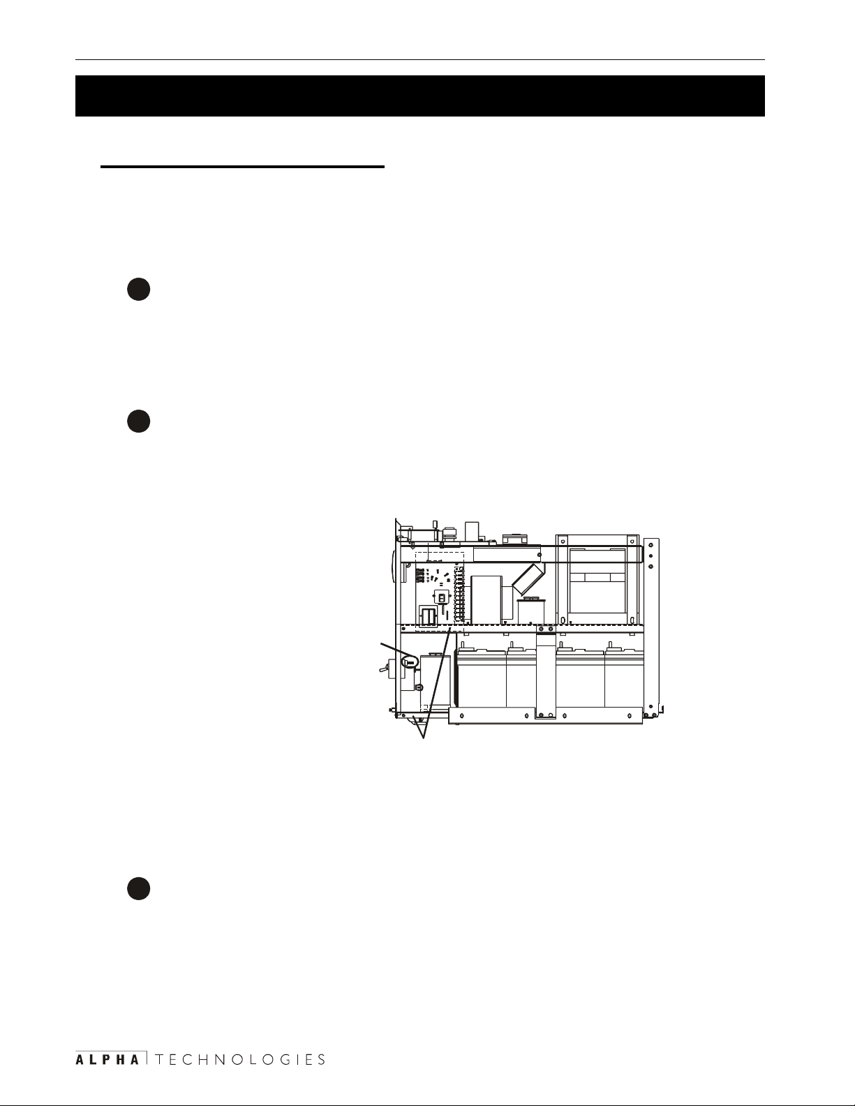
5 Maintenance 64
W
W
5.4 Replacing the Internal Batteries (Continued)
Step 2: Charger Voltage Test
This tests the unit’s charger so the new batteries will not damaged by a faulty charger . Do
this before removing the batteries.
Procedure:
Make sure:
1
• The Battery circuit breaker is switched off.
• The Input circuit breaker is switched on.
• The utility line is connected.
Measure the DC voltage by:
2
• Connecting the positive (+) to the top connector of the battery circuit breaker .
• Connecting the negative (–) to the chassis (Figure 5.2).
D
T102
1
2
TO OU T PU T R EC EP
T103
1
2
Positive (+) to top connector of
BA T T ERY CIRCUIT BREAKER.
Negative (-) to unit chassis.
V o ltage to be between
54 VDC to 57 VDC.
Figure 5.2
Charger V oltage Test
The voltage should be between 54 VDC to 57 VDC.
3
• If it is, switch off the Input circuit breaker , disconnect the utility line and go to S tep 3.
• If it is not, the charger is faulty . Cont act Alpha T echnologies customer service de-
partment.
Charger Voltage Test Finished
Page 71

65 5 Maintenance
5.4 Replacing the Internal Batteries (Continued)
Step 3: Battery Replacement
Procedure:
Disconnect the negative (black) battery lead
1
from the rear battery .
DANGER: Always remove this negative
lead first and connect it last.
Disconnect the positive (red) battery lead from
2
the front battery .
Remove the top shelf support and, if
3
attached, the seismic bracket.
Slide out the battery foam blocks and the
4
batteries.
Disconnect the batteries from each
5
other.
E
P
M
E
P
M
D
W4
TB1
K
1
2
G
3
G
4
5
6
7
8
9
10G
G
11
G
12
K
P
M
E
D
W4
TB1
K
1
2
G
3
G
4
5
6
7
8
9
10G
G
11
G
12
K
P
M
E
Page 72

5 Maintenance 66
5.4 Replacing the Internal Batteries (Continued)
Place the new batteries in the unit. Pay close attention to the polarities while con-
6
necting them as shown in Figure 5.3. Do not attach the unit’s negative or positive
leads.
Unit Positive
(Red) Lead
Unit Negative
(Black) Lead
Figure 5.3
Battery Connection
Put the battery foam blocks on top of the batteries.
7
Att ach the positive (red) battery lead to the front battery .
8
Att ach the negative (black) battery lead to the rear battery .
9
Reattach the cover and the front panel.
10
Reconnect the utility line and the external battery (if used).
11
12
Start the unit (Section 3.1). Do a self test (Section 3.3).
• If the unit passes the self test, turn it off (Section 3.2) and reconnect the load.
• If it doesn’t, check the battery connections or perform troubleshooting (Sections
3.4, 5.2).
Front of Unit
Restart the unit.
13
Battery Replacement Finished
Page 73

67 5 Maintenance
5.5 Configuring the Input/Output Voltage
The unit is factory configured to your input/output voltage specifications.
• Units configured only for 120 V AC input and output volt age need a new high voltage
board installed before re-configuring the input or output voltage. Contact Alpha Technologies customer service department.
• Units configured for 230 V AC, 50 Hz input and output cannot be re-configured.
• Units configured for 208 VAC or 240 VAC input voltage can be re-configured to 208 VAC
or 240 V AC input voltage.
• Units configured for 120/208 V AC output or 120/240 VAC output can be re-configured to
120/208 V AC or 120/240 VAC output.
DANGER: Lethal levels of voltages and currents are inside the unit when it is connected to line and battery power. The Input and Battery circuit breakers on the rear
panel must be switched off before starting this procedure.
Tools and Materials Required:
• Phillips and Slotted Screwdrivers.
Procedure:
Turn of f all loads. Make sure the Input and Battery circuit breakers on the rear panel are
1
switched off.
For the CFR 3000, remove the front panel and the cover as described in Step 1 of Section
2
5.4. Find the high voltage board labeled as “700–226–XX” (Figure 5.4).
Figure 5.4
High Volt age Board in CFR 3000
Page 74

5 Maintenance 68
5.5 Configuring the Input/Output Voltage (Continued)
For the CFR 3000RM, remove the front panel by unscrewing the 6 screws and lifting the
3
panel away . Make sure you do not damage or disconnect the ribbon cable connecting the
display panel to the unit. Find the high voltage board labeled as “700–226–XX” (Figure
5.5).
Figure 5.5
High Volt age Board in CFR 3000RM
On the high voltage board (Figure 5.6), reconfigure the wires and the jumpers as given in
4
Figure 5.7.
Reattach the front panel and cover . Turn the unit on (Section 3.1)
5
TIP: Y ou may want to measure the output voltage to make sure this procedure has been
done correctly .
V oltage Reconfiguration Finished
Page 75

69 5 Maintenance
5.5 Configuring the Input/Output Voltage (Continued)
W1
W2
W3
W5
W4
8
1112
910
JP1-JP6
Figure 5.6
High V oltage Board
3
4567
12
S1
TB1
noitarugifnoCdraoBegatloVhgiHnoitarugifnoCdraoBegatloVhgiH
noitarugifnoCdraoBegatloVhgiHnoitarugifnoCdraoBegatloVhgiH
noitarugifnoCdraoBegatloVhgiH
tupnItupnI
tupnItupnI
tupnI
egatloV
0210216PJ,4PJ,2PJ6&58&78------53-2
802802/0216PJ,3PJ,2PJ7&67&69252-1
802042/0216PJ,3PJ,1PJ7&67&69152-1
0320326PJ,4PJ,2PJ----------------7153-2
042802/0215PJ,4PJ,2PJ7&67&68253-2
042042/0215PJ,4PJ,1PJ7&67&68153-2
021802/0216PJ,4PJ,2PJ6&58&78253-2
021042/0216PJ,4PJ,1PJ6&58&78153-2
tuptuOtuptuO
tuptuOtuptuO
tuptuO
egatloV
High Volt age Board Configurations
sgnitteSrepmuJsgnitteSrepmuJ
sgnitteSrepmuJsgnitteSrepmuJ 1W1W1W1W1W 2W2W2W2W2W 3W3W3W3W3W 4W4W4W4W4W 5W5W5W5W5W 1S1S1S1S1S
sgnitteSrepmuJ
Figure 5.7
Page 76

5 Maintenance 70
5.6 Battery Run Times
The times in these charts are to be used in conjunction with the battery run time you measured in
Section 5.1, “Measuring the Battery Run Time.”
Tips:
• Y our run time can be different than shown in the chart s. Battery run time is affected by
temperature, battery age and condition and the size and type of the loads. Actual results
can vary by ± 15%.
• End of battery life is defined when the battery capacity falls below 80% of rated capacity .
• Times shown are averaged over a batch.
• All battery voltages are 48VDC.
• Times listed as 12:00 show the run time is 12 hours or more.
)0003RFC(sledoMrewoT)0003RFC(sledoMrewoT
)0003RFC(sledoMrewoT)0003RFC(sledoMrewoTsetuniM:sruoHnisemitllA
)0003RFC(sledoMrewoT
lanretnIlanretnI
lanretnIlanretnI
daoL%daoL%
daoL%daoL%)W(tuptuO)W(tuptuO
daoL%
)W(tuptuO)W(tuptuO)AV(tuptuO)AV(tuptuO
)W(tuptuO
)AV(tuptuO)AV(tuptuO
)AV(tuptuO
lanretnI
yrettaB
ylnO
1+1+1+1+1+
A84-PBEA84-PBE
A84-PBEA84-PBE
A84-PBE
1+1+1+1+1+
E84-PBEE84-PBE
E84-PBEE84-PBE
E84-PBE
2+2+2+2+2+
E84-PBEE84-PBE
E84-PBEE84-PBE
E84-PBE
3+3+3+3+3+
4+4+4+4+4+
E84-PBEE84-PBE
E84-PBEE84-PBE
E84-PBE
E84-PBEE84-PBE
E84-PBE
5+5+5+5+5+
E84-PBEE84-PBE
E84-PBEE84-PBE
E84-PBEE84-PBE
E84-PBE
6+6+6+6+6+
7+7+7+7+7+
E84-PBEE84-PBE
E84-PBEE84-PBE
E84-PBE
E84-PBEE84-PBE
E84-PBE
E84-PBEE84-PBE
0101010101002002
0202020202 004004
0303030303006006
0404040404 008008
050505050500010001
0606060606 00210021
070707070700410041
8787878787 05510551
585858585800710071
3939393939 05810581
001001
00100100020002
001
002002003003
002
004004 006006
004
006006009009
006
008008 00210021
008
0001000100510051
0001
00210021 00810081
0021
0041004100120012
0041
05510551 52325232
0551
0071007105520552
0071
05810581 57725772
0581
0002000200030003
0002
00300344:244:2
003
006006 24:124:1
006
00900911:111:1
009
00210021 45:045:0
0021
0051005124:024:0
0051
00810081 43:043:0
0081
0012001292:092:0
0012
52325232 52:052:0
5232
0552055222:022:0
0552
57725772 02:002:0
5772
0003000381:081:0
0003
44:244:265:765:7
44:2
24:124:1 15:415:4
24:1
11:111:102:302:3
11:1
45:045:0 82:282:2
45:0
24:024:055:155:1
24:0
43:043:0 33:133:1
43:0
92:092:071:171:1
92:0
52:052:0 80:180:1
52:0
22:022:000:100:1
22:0
02:002:0 45:045:0
02:0
81:081:094:094:0
81:0
65:765:755:1155:11
65:7
15:415:4 85:785:7
15:4
02:302:315:515:5
02:3
82:282:2 13:413:4
82:2
55:155:173.373.3
55:1
33:133:1 95:295:2
33:1
71:171:123:223:2
71:1
80:180:1 51:251:2
80:1
00:100:110:210:2
00:1
45:045:0 05:105:1
45:0
94:094:004:104:1
94:0
55:1155:11
55:11
85:785:7
85:7
15:515:505:0105:01
15:5
13:413:4 03:803:8
13:4
73.373.345:645:6
73.3
95:295:2 44:544:5
95:2
23:223:245:445:4
23:2
51:251:2 32:432:4
51:2
10:210:275:375:3
10:2
05:105:1 53:353:3
05:1
04:104:161:361:3
04:1
------------------------------------------------
-------- -------- -------- -------- -------- --------
05:0105:01
05:01
03:803:8
03:8
45:645:681:0181:01
45:6
44:544:5 93:893:8
44:5
45:445:432:732:7
45:4
32:432:4 83:683:6
32:4
75:375:300:600:6
75:3
53:353:3 72:572:5
53:3
61:361:395:495:4
61:3
----------------------------------------
-------- -------- -------- -------- --------
81:0181:01
81:01
93:893:8 43:1143:11
93:8
32:732:785:985:9
32:7
83:683:6 75:875:8
83:6
00:600:670:870:8
00:6
72:572:5 42:742:7
72:5
95:495:474:674:6
95:4
--------------------------------
43:1143:11
43:11
85:985:9
85:9
75:875:8 71:1171:11
75:8
70:870:871:0171:01
70:8
42:742:7 12:912:9
42:7
74:674:672:0172:01
74:6
-------- -------- --------
------------------------
71:1171:11 35:0135:01
71:11
71:0171:0163:963:9
71:01
12:912:9 23:823:8
12:9
72:0172:0193:793:7
72:01
35:0135:01
35:01
63:963:971:1171:11
63:9
23:823:8 20:0120:01
23:8
93:793:795:895:8
93:7
--------
71:1171:11
71:11
20:0120:01
20:01
95:895:8
95:8
Page 77

71 5 Maintenance
5.6 Battery Run Times (Continued)
setuniM:sruoHnisemitllA
daoL%daoL%
daoL%daoL%)W(tuptuO)W(tuptuO
daoL%
)W(tuptuO)W(tuptuO)AV(tuptuO)AV(tuptuO
)W(tuptuO
)AV(tuptuO)AV(tuptuOkcaP1kcaP1
)AV(tuptuO
kcaP1kcaP1skcaP2skcaP2
kcaP1
skcaP2skcaP2skcaP3skcaP3
skcaP2
skcaP3skcaP3skcaP4skcaP4
skcaP3
skcaP4skcaP4skcaP5skcaP5
skcaP4
skcaP5skcaP5skcaP6skcaP6
skcaP5
skcaP6skcaP6skcaP7skcaP7
skcaP6
skcaP7skcaP7skcaP8skcaP8
skcaP7
skcaPyrettaBMR84-714PBEhtiw)MR0003RFC(sledoMtnuoMkcaR skcaPyrettaBMR84-714PBEhtiw)MR0003RFC(sledoMtnuoMkcaR
skcaPyrettaBMR84-714PBEhtiw)MR0003RFC(sledoMtnuoMkcaR skcaPyrettaBMR84-714PBEhtiw)MR0003RFC(sledoMtnuoMkcaR
skcaPyrettaBMR84-714PBEhtiw)MR0003RFC(sledoMtnuoMkcaR
skcaP8skcaP8skcaP9skcaP9
skcaP8
skcaP9skcaP9skcaP01skcaP01
skcaP9
skcaP01skcaP01
skcaP01
0101010101002002
0202020202 004004
0303030303006006
0404040404 008008
050505050500010001
0606060606 00210021
070707070700410041
8787878787 05510551
585858585800710071
3939393939 05810581
001001
00100100020002
001
daoL%daoL%
daoL%daoL%)W(tuptuO)W(tuptuO
daoL%
0101010101002002
002002003003
002
004004 006006
004
006006009009
006
008008 00210021
008
0001000100510051
0001
00210021 00810081
0021
0041004100120012
0041
05510551 52325232
0551
0071007105520552
0071
05810581 57725772
0581
0002000200030003
0002
)W(tuptuO)W(tuptuO)AV(tuptuO)AV(tuptuO
)W(tuptuO
002002003003
002
00300394:094:0
003
006006 23:023:0
006
00900932:032:0
009
00210021 71:071:0
0021
0051005131:031:0
0051
00810081 11:011:0
0081
0012001280:080:0
0012
52325232 70:070:0
5232
0552055260:060:0
0552
57725772 50:050:0
5772
0003000340:040:0
0003
)AV(tuptuO)AV(tuptuOkcaP1kcaP1
)AV(tuptuO
00300344:244:2
003
setuniM:sruoHnisemitllA
94:094:000:200:2
94:0
23:023:0 91:191:1
23:0
32:032:085:085:0
32:0
71:071:0 54:054:0
71:0
31:031:063:063:0
31:0
11:011:0 92:092:0
11:0
80:080:052:052:0
80:0
70:070:0 22:022:0
70:0
60:060:091:091:0
60:0
50:050:0 71:071:0
50:0
40:040:061:061:0
40:0
kcaP1kcaP1skcaP2skcaP2
kcaP1
44:244:265:765:7
44:2
00:200:202:302:3
00:2
91:191:1 31:231:2
91:1
85:085:083:183:1
85:0
54:054:0 61:161:1
54:0
63:063:010:110:1
63:0
92:092:0 05:005:0
92:0
52:052:024:024:0
52:0
22:022:0 83:083:0
22:0
91:091:043:043:0
91:0
71:071:0 13:013:0
71:0
61:061:082:082:0
61:0
skcaP2skcaP2skcaP3skcaP3
skcaP2
65:765:7------------
65:7
02:302:344:444:4
02:3
31:231:2 21:321:3
31:2
83:183:112:212:2
83:1
61:161:1 94:194:1
61:1
10:110:182:182:1
10:1
05:005:0 31:131:1
05:0
24:024:020:120:1
24:0
83:083:0 55:055:0
83:0
43:043:005:005:0
43:0
13:013:0 54:054:0
13:0
82:082:014:014:0
82:0
skcaP3skcaP3skcaP4skcaP4
skcaP3
------------------------
------
44:444:401:601:6
44:4
21:321:3 31:431:4
21:3
12:212:270:370:3
12:2
94:194:1 52:252:2
94:1
82:182:175:175:1
82:1
31:131:1 73:173:1
31:1
20:120:122:122:1
20:1
55:055:0 31:131:1
55:0
05:005:060:160:1
05:0
54:054:0 00:100:1
54:0
14:014:055:055:0
14:0
skcaP4skcaP4skcaP5skcaP5
skcaP4
------------------------
------
01:601:653:753:7
01:6
31:431:4 51:551:5
31:4
70:370:345:345:3
70:3
52:252:2 30:330:3
52:2
75:175:182:282:2
75:1
73:173:1 30:230:2
73:1
22:122:144:144:1
22:1
31:131:1 33:133:1
31:1
60:160:142:142:1
60:1
00:100:1 61:161:1
00:1
55:055:090:190:1
55:0
skcaP5skcaP5skcaP6skcaP6
skcaP5
------------------------
------
53:753:775:875:8
53:7
51:551:5 81:681:6
51:5
45:345:344:444:4
45:3
30:330:3 14:314:3
30:3
82:282:295:295:2
82:2
30:230:2 92:292:2
30:2
44:144:170:270:2
44:1
33:133:1 35:135:1
33:1
42:142:124:124:1
42:1
61:161:1 23:123:1
61:1
90:190:142:142:1
90:1
skcaP6skcaP6skcaP7skcaP7
skcaP6
------------------------
------
75:875:861:0161:01
75:8
81:681:6 91:791:7
81:6
44:444:423:523:5
44:4
14:314:3 12:412:4
14:3
95:295:223:323:3
95:2
92:292:2 75:275:2
92:2
70:270:203:203:2
70:2
35:135:1 41:241:2
35:1
24:124:110:210:2
24:1
23:123:1 94:194:1
23:1
42:142:104:104:1
42:1
skcaPyrettaBMRA84PBEhtiw)MR0003RFC(sledoMtnuoMkcaRskcaPyrettaBMRA84PBEhtiw)MR0003RFC(sledoMtnuoMkcaR
skcaPyrettaBMRA84PBEhtiw)MR0003RFC(sledoMtnuoMkcaRskcaPyrettaBMRA84PBEhtiw)MR0003RFC(sledoMtnuoMkcaR
skcaPyrettaBMRA84PBEhtiw)MR0003RFC(sledoMtnuoMkcaR
skcaP7skcaP7skcaP8skcaP8
skcaP7
------------------------
------
61:0161:0153:1153:11
61:01
91:791:7 91:891:8
91:7
23:523:502:602:6
23:5
12:412:4 10:510:5
12:4
23:323:350:450:4
23:3
75:275:2 52:352:3
75:2
03:203:245:245:2
03:2
41:241:2 63:263:2
41:2
10:210:202:202:2
10:2
94:194:1 70:270:2
94:1
04:104:165:165:1
04:1
skcaP8skcaP8skcaP9skcaP9
skcaP8
------------------------
------
53:1153:1100:2100:21
53:11
91:891:8 81:981:9
91:8
02:602:680:780:7
02:6
10:510:5 14:514:5
10:5
50:450:493:493:4
50:4
52:352:3 35:335:3
52:3
45:245:281:381:3
45:2
63:263:2 85:285:2
63:2
02:202:204:204:2
02:2
70:270:2 52:252:2
70:2
65:165:131:231:2
65:1
skcaP9skcaP9skcaP01skcaP01
skcaP9
------------------------
------
00:2100:21
00:21
81:981:9
81:9
80:780:7
80:7
14:514:5
14:5
93:493:4
93:4
35:335:3
35:3
81:381:3
81:3
85:285:2
85:2
04:204:2
04:2
52:252:2
52:2
31:231:2
31:2
skcaP01skcaP01
skcaP01
------------
-----0202020202 004004
0303030303006006
0404040404 008008
050505050500010001
0606060606 00210021
070707070700410041
8787878787 05510551
585858585800710071
3939393939 05810581
001001
00100100020002
001
004004 006006
004
006006009009
006
008008 00210021
008
0001000100510051
0001
00210021 00810081
0021
0041004100120012
0041
05510551 52325232
0551
0071007105520552
0071
05810581 57725772
0581
0002000200030003
0002
006006 24:124:1
006
00900911:111:1
009
00210021 45:045:0
0021
0051005124:024:0
0051
00810081 43:043:0
0081
0012001292:092:0
0012
52325232 52:052:0
5232
0552055222:022:0
0552
57725772 02:002:0
5772
0003000381:081:0
0003
24:124:1 15:415:4
24:1
11:111:102:302:3
11:1
45:045:0 82:282:2
45:0
24:024:055:155:1
24:0
43:043:0 33:133:1
43:0
92:092:071:171:1
92:0
52:052:0 80:180:1
52:0
22:022:000:100:1
22:0
02:002:0 45:045:0
02:0
81:081:094:094:0
81:0
15:415:4 30:930:9
15:4
02:302:321:621:6
02:3
82:282:2 43:443:4
82:2
55:155:1233:3233:3
55:1
33:133:1 94:294:2
33:1
71:171:191:291:2
71:1
80:180:1 20:220:2
80:1
00:100:184:184:1
00:1
45:045:0 73:173:1
45:0
94:094:072:172:1
94:0
30:930:9 ------------
30:9
21:621:693:993:9
21:6
43:443:4 60:760:7
43:4
233:3233:392:592:5
233:3
94:294:2 32:432:4
94:2
91:291:253:353:3
91:2
20:220:2 80:380:3
20:2
84:184:164:264:2
84:1
73:173:1 82:282:2
73:1
72:172:131:231:2
72:1
------------ ------------
------
93:993:9------------
93:9
60:760:7 10:0110:01
60:7
92:592:544:744:7
92:5
32:432:4 01:601:6
32:4
53:353:330:530:5
53:3
80:380:3 52:452:4
80:3
64:264:235:335:3
64:2
82:282:2 82:382:3
82:2
31:231:260:360:3
31:2
------------ ------------
------
------------------------
-----10:0110:01 ------------
10:01
44:744:731:0131:01
44:7
01:601:6 01:801:8
01:6
30:530:514:614:6
30:5
52:452:4 05:505:5
52:4
35:335:390:590:5
35:3
82:382:3 43:443:4
82:3
60:360:360:460:4
60:3
------------ ------------
------
------------------------
------
------------ ------------
-----31:0131:01------------
31:01
01:801:8 12:0112:01
01:8
14:614:692:892:8
14:6
05:505:5 42:742:7
05:5
90:590:523:623:6
90:5
43:443:4 84:584:5
43:4
60:460:411:511:5
60:4
------------ ------------
------
------------------------
------
------------ ------------
------
------------------------
-----12:0112:01 ------------
12:01
92:892:852:0152:01
92:8
42:742:7 60:960:9
42:7
23:623:610:810:8
23:6
84:584:5 70:770:7
84:5
11:511:532:632:6
11:5
------------ ------------
------
------------------------
------
------------ ------------
------
------------------------
------
------------ ------------
-----52:0152:01------------
52:01
60:960:9 35:0135:01
60:9
10:810:863:963:9
10:8
70:770:7 23:823:8
70:7
32:632:693:793:7
32:6
------------ ------------
------
------------------------
------
------------ ------------
------
------------------------
------
------------ ------------
------
------------------------
-----35:0135:01 ------------
35:01
63:963:971:1171:11
63:9
23:823:8 20:0120:01
23:8
93:793:793:893:8
93:7
------------
------
------------
------
------------
------
------------
------
------------
------
------------
------
------------
-----71:1171:11
71:11
20:0120:01
20:01
93:893:8
93:8
Page 78

5 Maintenance 72
5.7 Specifications
snoitacificepSnommoCsnoitacificepSnommoC
snoitacificepSnommoCsnoitacificepSnommoC
snoitacificepSnommoC
)zH(ycneuqerFtupnI)zH(ycneuqerFtupnI
)zH(ycneuqerFtupnI)zH(ycneuqerFtupnI
)zH(ycneuqerFtupnI
noitairaVegatloVtupnInoitairaVegatloVtupnI
noitairaVegatloVtupnInoitairaVegatloVtupnI
noitairaVegatloVtupnI
)zH(ycneuqerFtuptuO)zH(ycneuqerFtuptuO
)zH(ycneuqerFtuptuO)zH(ycneuqerFtuptuO
edomretrevnI
tuptuOtaeHtuptuOtaeH
tuptuOtaeHtuptuOtaeH
tuptuOtaeH
)zH(ycneuqerFtuptuO
)CAV(noitalugeRtuptuO)CAV(noitalugeRtuptuO
)CAV(noitalugeRtuptuO)CAV(noitalugeRtuptuO
)CAV(noitalugeRtuptuO
)daoLlacipyT(ycneiciffE)daoLlacipyT(ycneiciffE
)daoLlacipyT(ycneiciffE)daoLlacipyT(ycneiciffE
)daoLlacipyT(ycneiciffE
noitrotsiDcinomraHlatoTnoitrotsiDcinomraHlatoT
noitrotsiDcinomraHlatoTnoitrotsiDcinomraHlatoT
noitrotsiDcinomraHlatoT
mrofevaWtuptuOmrofevaWtuptuO
mrofevaWtuptuOmrofevaWtuptuO
mrofevaWtuptuO
esnopseRdaoLpetSesnopseRdaoLpetS
esnopseRdaoLpetSesnopseRdaoLpetS
esnopseRdaoLpetS
noitaunettAesioNnoitaunettAesioN
noitaunettAesioNnoitaunettAesioN
noitaunettAesioN
erutarepmeTgnitarepOerutarepmeTgnitarepO
erutarepmeTgnitarepOerutarepmeTgnitarepO
erutarepmeTgnitarepO
m1@esioNelbiduAm1@esioNelbiduA
m1@esioNelbiduAm1@esioNelbiduA
m1@esioNelbiduA
3±05
3±06
CAV%01+ot%02-
zH1.0±
%1±
%09
%5<
eniS
daol%001@%01<
Bd021-:edomnommoC
)ZHM1otzHK001(
001(Bd06-:edoMlamroN
)zHM1otzHK
)C°04-°0(F°401-°23
W032,h/UTB587
ABd54<:0003
ABd06<:MR0003
snoitacificepSlacinahceMsnoitacificepSlacinahceM
snoitacificepSlacinahceMsnoitacificepSlacinahceM
snoitacificepSlacinahceM
00030003
00030003 MR0003MR0003
0003
snoisnemiDsnoisnemiD
snoisnemiDsnoisnemiD
snoisnemiD
)mm(ni,DxHxW
)gk(sbl,thgieW)gk(sbl,thgieW
)gk(sbl,thgieW)gk(sbl,thgieW
zH06
zH05
)CAV(
)gk(sbl,thgieW
snoitacificepSlacirtcelEsnoitacificepSlacirtcelE
snoitacificepSlacirtcelEsnoitacificepSlacirtcelE
snoitacificepSlacirtcelE
sledoMzH06sledoMzH06
sledoMzH06sledoMzH06
sledoMzH06
)AV(rewoPtuptuO)AV(rewoPtuptuO
)AV(rewoPtuptuO)AV(rewoPtuptuO
)AV(rewoPtuptuO
)W(rewoPevitcA)W(rewoPevitcA
)W(rewoPevitcA)W(rewoPevitcA
)W(rewoPevitcA
)CAV(egatloVtupnI)CAV(egatloVtupnI
)CAV(egatloVtupnI)CAV(egatloVtupnI
)CAV(egatloVtupnI
tupnImumixaMtupnImumixaM
tupnImumixaMtupnImumixaM
tupnImumixaM
)spmA(tnerruC
egatloVtuptuOegatloVtuptuO
egatloVtuptuOegatloVtuptuO
egatloVtuptuO
tuptuOmumixaMtuptuOmumixaM
tuptuOmumixaMtuptuOmumixaM
tuptuOmumixaM
)spmA(tnerruC
0.03x3.12x5.8
)267x145x612(
)821(382
)131(882
0003
0002
11/21/12
MR0003MR0003
MR0003
51x5.01x71
)183x762x234(
)95(031
)16(531
042/802/021
042/802/021
5.21/4.41/52
snoitacificepSyrettaBsnoitacificepSyrettaB
snoitacificepSyrettaBsnoitacificepSyrettaB
snoitacificepSyrettaB
epytdednemmoceRepytdednemmoceR
epytdednemmoceRepytdednemmoceR
epytdednemmoceR
)CDV(egatloV)CDV(egatloV
)CDV(egatloV)CDV(egatloV
)CDV(egatloV
epyTregrahCepyTregrahC
epyTregrahCepyTregrahC
epyTregrahC
)CDV(egatloVregrahC)CDV(egatloVregrahC
)CDV(egatloVregrahC)CDV(egatloVregrahC
)CDV(egatloVregrahC
snoitacinummoCsnoitacinummoC
snoitacinummoCsnoitacinummoC
snoitacinummoC
srotacidnIsrotacidnI
srotacidnIsrotacidnI
srotacidnI
slortnoCslortnoC
slortnoCslortnoC
slortnoC
srotcennoCsrotcennoC
srotcennoCsrotcennoC
srotcennoC
smralAelbiduAsmralAelbiduA
smralAelbiduAsmralAelbiduA
smralAelbiduA
smralAtuptuOsmralAtuptuO
smralAtuptuOsmralAtuptuO
smralAtuptuO
84
)CDV(tuotuCegatloVwoL)CDV(tuotuCegatloVwoL
)CDV(tuotuCegatloVwoL)CDV(tuotuCegatloVwoL
)CDV(tuotuCegatloVwoL
24
.)11
,detalugerevlaV
.eerfecnanetniam
)xaMspmA3(raeniL
C°52ta2.55
,eruliaFeniL,tneserPeniL
woL,gninraWyrettaBwoL
,tseT,nwodtuhSyrettaB
.ecivreS
)tseT(tratSlaunaM,ffomralA
-SR)54-JR(mralAlanretxE
-JR(DIIlanretxE,)9-BD(232
yrettaBwoL,eruliaFeniL
dedeenecivreS,gninraW
rotcennoc54-JRlenapraeR
rofstcatnocCmroFhtiw
eruliaFeniL/tneserPeniL
yrettaBwoL/KOyrettaBdna
.gninraW
NOTES:
1) Specifications subject to change without notice.
2) These specifications are based upon use with computer-
type loads with a crest factor of 3:1 (Max) and a typical power
factor of 0.67.
sledoMzH05sledoMzH05
sledoMzH05sledoMzH05
sledoMzH05
)AV(rewoPtuptuO)AV(rewoPtuptuO
)AV(rewoPtuptuO)AV(rewoPtuptuO
)AV(rewoPtuptuO
)W(rewoPevitcA)W(rewoPevitcA
)W(rewoPevitcA)W(rewoPevitcA
)W(rewoPevitcA
)CAV(egatloVtupnI)CAV(egatloVtupnI
)CAV(egatloVtupnI)CAV(egatloVtupnI
)CAV(egatloVtupnI
tupnImumixaMtupnImumixaM
tupnImumixaMtupnImumixaM
tupnImumixaM
)spmA(tnerruC
egatloVtuptuOegatloVtuptuO
egatloVtuptuOegatloVtuptuO
)CAV(
tupnItupnI
tupnItupnI
tupnI
zH06zH06
zH06zH06,19M-1.701oN2.22C.dtSASC
zH06
zH05zH05
zH05zH05,059CEI,05906NE,1-19005NE
zH05
skraMskraM
skraMskraM
skraM
egatloVtuptuO
tuptuOmumixaMtuptuOmumixaM
tuptuOmumixaMtuptuOmumixaM
tuptuOmumixaM
)spmA(tnerruC
CAV021
yrettaByrettaB
yrettaByrettaB
yrettaB
CAV042/032/802
oTecnailpmoCoTecnailpmoC
oTecnailpmoCoTecnailpmoC
oTecnailpmoC
lacideMzH06lacideMzH06
lacideMzH06lacideMzH06-1.106oN2.22CASC:sulpzH06reP
lacideMzH06
lacideMzH05lacideMzH05
lacideMzH05lacideMzH05-1.106oN2.22CASC:sulpzH05reP
lacideMzH05
0003
0002
032
11
032
31
sgnitaRrekaerBtiucriCsgnitaRrekaerBtiucriC
sgnitaRrekaerBtiucriCsgnitaRrekaerBtiucriC
sgnitaRrekaerBtiucriC
spmA52
spmA51
spmA001
8771LU
dn
)dE
2(1-10606oNdtSLU,09M
4-641CEI
dn
)dE
2(1-10606oNdtSLU,09M
ASC
:zH06
C
SU
EC:zH05,
Page 79

73
Index
120 VAC Output
Connecting Loads To .....................................23–25
3000
Battery Charger T est........................................... 64
Battery Replacement .....................................62–66
Battery Runtime T able ........................................ 70
Cover, Removal..............................................62–63
Front Panel........................................................... 5
Installation.......................................................... 13
Removal of Seismic Brackets ............................ 14
Voltage, Input/Output Reconfiguration Board ...... 67
3000RM
Battery Runtime T able ........................................ 71
Connection of External Battery Pack .............18–19
Difference from 3000 ............................................ 5
Front Panel........................................................... 6
Installation.......................................................... 14
Voltage, Input/Output Reconfiguration Board ...... 68
A
Adjusting Unit to Local Line Conditions ............... 49
Alpha, Returning Unit to for Repair ...................... 62
Alarm, External Connector ................................ 9, 20
Alarm Off Button on SID Panel.............................. 33
Alarms
On Display Panel ...........................................32–34
RS–232 .........................................................38–40
Starting/S topping of RS–232 Transmission ......... 48
Alarms, Turning Off Audible Alarm ....................... 33
Attaching an External Modem..........................50–57
Attaching Seismic Brackets to Floor ..................... 13
B
Backup Generator, use of ...................................... 12
Backup Power, Measuring Battery........................ 59
Backup Power, T ime for Different Battery S trings...
............................................................................70–71
Battery
Alarms, RS–232 ................................................. 39
Alarms, Display Panel ...................................32–33
Charger Status ................................................... 44
Charger T est ....................................................... 64
Circuit Breaker ..................................................... 8
Discharged Battery Indicators ........................32–33
Disposal ...............................................................iii
External Battery Pack Installation..................18–19
Inverter On/Off via RS–232 ................................. 47
Lifetime .............................................................. 60
Low Battery Warning............................... 20, 21, 32
Low Battery Shutdown......................................... 33
Measuring Back Up Time ................................... 59
Parameters, RS–232 ..............................................
................................ See RS–232 Communications
Preventing Battery Discharge................................ 8
Replacement ............................................ iii, 62–66
Run Time Tables ................................................ 70
Safety Checklists ............................................. ii–iii
Starting Unit with Battery Power .................... 28, 33
Storage....................................................... ii–iii, 18
String Voltage..................................................... 44
Buzzer, Turning Off Audible Alarm ....................... 33
C
Circuit Breakers
Battery.................................................................. 8
Dedicated for Input ............................................. 12
Input ..................................................................... 8
Output .................................................................. 7
CFR 3000, 3000RM
Alarms On Display Panel...............................32–34
Alarms, RS-232 .............................................39–40
Battery Backup Time, Measuring........................ 59
Battery Circuit Breaker ......................................... 8
Changing Input/Output Voltage ......................67–69
Computer Connection and Control .................35–57
Connecting to Loads and Utility Line ..............15–16
Connecting to Noisy Equipment .......................... 11
Controlling Unit With Display Panel................32–35
Discharged Battery Indicator..........................32–33
Dedicated Input Line Circuit Breaker .................. 12
Difference Between 3000 and 3000RM.................. 5
External Alarm Connector ............................... 9, 20
External Battery Connector ........................8, 18–19
External IID Connector...........................................9
External Ground Lug ............................................. 8
External Modem .............................................50–58
Factory Repairs .................................................. 62
Fans, Cooling ................................................... 6, 7
Front Panel....................................................... 5–6
Generator, external, use of.................................. 12
LAN Connector ............................................... 9, 22
Line Cord .............................................................. 8
Line Synchronization........................................... 33
Measuring Input, Output and Battery Parameters....
................................ See RS–232 Communications
Output Loading Display....................................... 34
Output Circuit Breaker and Connectors ................ 7
Output Shutdown, How Display Panel Shows ...... 34
Output T ransformer Maximum Current............23–25
Rear Panel............................................................ 7
Page 80

Index
74
Front Panel ............................................................6
RS–232 Connector.......................................... 9, 21
Site Specifications.......................................... 9, 11
Starting with Battery Power ........................... 28, 33
Synchronization With Line Power........................ 33
Testing ............................................................... 30
Troubleshooting .......................................31, 60–61
T urn Unit On/Off ............................................27–29
Unpacking Checklist ............................................ 3
Changing Internal Batteries (3000 only)...........62–66
Changing Input/Output V oltage ........................67–69
Charger, Battery, Test ............................................. 64
Charger, Battery, Status ......................................... 44
Checklists
Battery Safety................................................... ii–iii
General Safety...................................................... ii
Pre–Installation................................................... 11
Common Problems............................................60–61
Computer
Also See RS–232 Communications
Communications Parameters........................ 21, 37
Connecting to a Computer .................................. 21
Controlling Unit With......................................38–49
External Modem Connection ..........................50–57
LAN Connection and Control ............................... 22
With Windows HyperT erminal ........................36–37
Detection and Warning Values for Line................ 49
Discharged Battery Indicator ........................... 32, 33
Discharging Battery , how to prevent....................... 8
Display Panel, SID .................................................... 5
Measuring Output Power ..................................... 34
Self Test of Unit With ......................................... 30
T roubleshooting With.......................................... 31
Using .............................................................32–34
E
Electromagnetic Radiation from Unit.................... 27
Electrically Noisy Devices, Connection of ............ 11
Emergency Power Off Switch................................ 20
Emergency Shutdown Procedure .............................
.......................................................Inside Rear Cover
Emergency T echnical Support ................................ 4
Environmental Requirements................................ 11
External Alarm Connector ................................. 9, 20
External Battery Pack Installation....................18–19
External IID Connector............................................. 9
External Modem ....... See RS–232 Communications
Connecting
Electrically Noisy Devices................................... 11
External Alarm Port ............................................ 20
External Battery Pack....................................18–19
External Modem.............................................50–57
Internal Batteries (3000 Only) ........................65–66
LAN Connector ................................................... 22
Loads and Utility Line ....................................15–17
RS–232 Port ....................................................... 21
With Windows HyperT erminal ........................36–37
Controlling Unit with SID Panel .......................32–34
Cover, Removing (3000 Only)............................62–63
Cooling Unit .......................................................... 6–7
Current, Output
Maximum Current Rating for Output T ransformer. 2 3
Measuring ......................................................24–25
Customer T echnical Support ................................... 4
D
Damaged Items During Shipping ............................ 3
Dedicated Input Circuit Breaker for Line.............. 12
F
Factory , Return to For Repair ................................ 62
Fans, Internal........................................................ 6–7
Faults, T roubleshooting ..............................31, 60–61
Faulty Battery Charger, Testing for ....................... 64
Flashing LEDs ....................................................32–34
Floor, Att aching Seismic Brackets to.................... 13
Front Panel Removal (3000 Only).......................... 63
G
Generator, Standby ................................................ 12
Ground Lug, External............................................... 8
Grounding Requirements....................................... 11
H
HyperT erminal, RS–232 Set Up .................................
................................... See RS–232 Communications
Page 81

75
Index
I
IID
External Connector ............................................... 9
Location of........................................................ 5, 6
Input Alarms, RS–232 ............................................. 39
Input Circuit Breaker ................................................ 8
Input Values, Measuring via RS–232.........................
................................... See RS–232 Communications
Input Voltage, Acceptable Values of ..................... 11
Input Voltage, Changing ................................... 67–69
Input Wiring .......................................................15–16
Inspection Checklist .........See Unpacking Checklist
Installation
Installation Checklist .......................................ii, 11
T ower Models ...................................................... 13
Rack Mount Models ............................................ 14
Inverter On/Off via RS–232..................................... 47
Internal Battery Replacement (3000 Only).......62–66
Items Damaged in Shipping .................................... 3
M
Magnetic Field Produced by Unit.......................... 27
Maintenance Parameters, RS–232 .................. 41, 49
Malfunctions, Troubleshooting ...................31, 60–61
Manual Start Button On SID Panel........................ 33
Measuring
Battery Backup Time.......................................... 59
Battery String Voltage......................................... 44
Outpu t Curr ent...............................................23–25
Output Loading ................................................... 34
Input, Output and Battery Parameters via RS–232..
................................ See RS–232 Communications
Menu Tree, RS–232................................................. 41
Modem, External ...... See RS–232 Communications
Monitoring, Remote............ See Remote Monitoring
Mounting to Floor ................................................... 13
N
No Line, Starting Unit With .................................... 28
L
LAN Port .................................................................. 22
LEDs Flashing ....................................................32–34
LEDs On Display Panel......................................32–33
Lifetime, Battery ..................................................... 60
Line Alarms, RS–232 .............................................. 39
Line, Adjusting Unit T o Meet Local Conditions.... 49
Line, Attaching Dedicated Input Circuit Breaker . 12
Line Failure LED..................................................... 32
Line Present LED .................................................... 32
Line, Starting Unit With No Line .............................2 8
Line Voltage, Acceptable Ranges......................... 11
Line Synchronization ............................................. 33
Loads
Output Loading Indicator..................................... 34
Overloading Output T ransformer ....................23–25
Wiring............................................................15–16
Low Battery Warning ............................................. 32
Low Battery Shutdown........................................... 33
O
Odors given off by unit........................................... 27
On/Off, T urning Unit...........................................27–29
Opening Menu, RS–232..............................................
................................... See RS–232 Communications
Opening the Case (3000 Only) ..........................62–63
Operating Unit With SID Panel.........................32–34
Output
Alarms, RS–232 ................................................. 40
Circuit Breaker ..................................................... 7
Connectors ........................................................... 7
Emergency Shutdown Switch .............................. 20
Loading Display .................................................. 34
Measuring Battery Backup Time ......................... 59
Measuring via RS–232 ............................................
................................ See RS–232 Communications
Shutdown, How Display Panel Shows.................. 34
Shutdown via RS–232 ....................................46–47
Synchronization, Input with Output...................... 33
T ransformer, Maximum Output Current................ 23
Output Voltage, Changing..............................67–69
Wiring............................................................15–16
Overloaded Unit, Display Panel Shows................ 34
Overloading the Output Transformer.................... 23
Location Requirements for Unit ............................ 11
Page 82

Index
76
P
Pack, External Battery, Installation..................18–19
Panel, Operate Unit With SID........................... 32–34
Panel, Front, Removing (3000 Only) ..................... 63
Parts, Ordering ......................................................... 4
Password, RS–232 .................................................. 38
Power Off Switch, Emergency............................... 20
Preventing Battery Drainage ................................... 8
Problems, Common...........................................60–61
R
Rack Mounting (3000 RM Only) .............................. 14
Rear Panel ............................................................ 7–9
Reconfiguring Input/Output V oltage ................67–69
Remote Monitoring With
Also See RS–232 Communications
External Alarm Panel .......................................... 20
LAN .................................................................... 22
RS–232 .........................................................38–50
Remote IID ........................................................... 9
Removing Cover (3000 Only) ............................62–63
Return to Factory For Repair ................................. 62
Replacing Internal Batteries (3000 Only) ... iii, 62–66
RS–232 Communications
Alarms...........................................................38–40
Battery Parameters............................................. 44
Communication Parameters.......................... 21, 37
Connector ............................................................. 9
External Modem Connection and Use ............50–57
Input Parameters ................................................ 42
Maintenance Parameters .................................... 49
Menu T ree........................................................... 41
Opening Menu, Using ....................................38–40
Output Parameters ............................................. 43
Password............................................................ 38
Password Changing ............................................ 46
Self Test Start/Stop............................................ 42
Shutdown Parameters......................................... 46
Stop Transmission of Alarms.............................. 48
System Parameters............................................ 42
User Parameters ................................................ 45
Windows HyperT erminal Set Up .....................36–37
Wiring ................................................................. 21
Run Time, Battery
Measuring ........................................................... 59
Run Time Tables ...........................................70–71
S
Safety Checklists .................................................ii–iii
Seismic Brackets
Attaching to Floor ............................................... 13
Removing ........................................................... 14
Self T est................................................................... 30
Self T est, Starting via RS–232................................ 45
Service Alarms, RS–232 ......................................... 40
Sharing Loads in Output Transformer .............23–25
Shutdown Parameters, RS–232 ........................46–47
Shutdown Procedure
Emergency ................................. Inside Rear Cover
Emergency Power Off Switch.............................. 20
How Unit Shows A Shutdown .............................. 34
Normal ............................................................... 29
Output Shutdown via RS–232 ............................. 46
SID Display Panel ..............................................32–34
Specifications
General Unit ....................................................... 72
Battery Run times..........................................70–71
Standby Generator, use of ..................................... 12
Starting/T urning Off Unit ...................................27–29
Starting Unit With Battery Power .................... 28, 33
Storage of Batteries, T esting of Before Use ....iii, 18
String, Battery Voltage Measuring ........................ 44
Support, Technical ................................................... 4
Switch, Emergency Power Off............................... 20
Synchronization, of unit to Line............................ 33
System Parameters, RS–232............................ 41, 42
T
T echnical Support .................................................... 4
Terminal Block Wiring Specifications .................. 17
Test LED on SID Panel ........................................... 33
T esting Battery Backup Time................................. 59
Backup Time...................................................... 59
Run Time Tables ...........................................70–71
T esting Battery Charger ......................................... 64
T esting, Self Test With SID..................................... 30
Time, Battery Backup Time, Measuring ............... 59
Page 83

77
Index
Transformer Output, Overloading ......................... 23
Troubleshooting...........................................31, 60–61
T ower Mounting (3000 Only) .............................13–14
Turning Off Audible Alarm ..................................... 33
T urning Unit On/Off............................................27–29
U
Unpacking Checklist ................................................. 3
Utility Line
Acceptable Input Voltages ................................. 11
Adjusting Unit to Local Line Conditions............... 49
Dedicated Circuit Breaker................................... 11
Labels, on Utility Panel, Placing ......................... 11
Measuring via RS–232 ............................................
................................ See RS–232 Communications
Present, Display Panel Shows ............................ 32
Wiring T o.......................................................15–16
User Parameters, RS–232............................41, 45–48
V
Voltage
Adjusting Unit to Local Line Voltages ................. 49
Changing Voltage, Input/Output .....................67–69
Battery Charger Voltage Test .............................. 64
Battery String Voltage Measurement................... 44
Line, Acceptable Ranges.................................... 11
Input/Output Measuring via RS–232........................
................................ See RS–232 Communications
Output ................................................................ 23
Wiring
Alarm Port .......................................................... 20
Battery (3000 Only) ........................................65–66
Checklist .........................................................ii, 11
External Alarm Port ............................................ 20
External Battery Pack................................ii, 18–19
LAN Port............................................................. 22
Loads and Line ..............................................15–17
RS–232 Port ....................................................... 21
W
Warnings
Labels, on Utility Panel, Placing ......................... 11
Line Failure......................................................ii, 11
Low Battery......................................................... 32
Malfunction ................................................ ii, 11, 32
No Utility Line ..................................................... 32
RS–232 ................... See RS–232 Communications
Warranty.................................................................. 78
Windows HyperTerminal............................................
................................... See RS–232 Communications
Page 84

Warranty
Alpha Technologies warrants its equipment to be free of manufacturing defects in material and workmanship
for a period of 24 months from the date of manufacture. The liability of Alpha Technologies under this warranty
is solely limited to repairing, replacing, or issuing credit for such equipment (at the discretion of Alpha
Technologies), provided that:
1.Alpha Technologies’ Customer Service Department is promptly notified, by facsimile or telephone, that
a failure or defect has occurred.
2. Alpha Technologies’ Customer Service Department issues a Return Materials Authorization (RMA)
number, and designates the service location. The RMA must be clearly marked on the outside of the
shipping container.
3.Purchaser is responsible for all in-bound shipping and handling charges (COD and freight collect will
not be accepted without prior approval from Alpha Technologies); Alpha Technologies will pay out-bound
surface shipping charges for return of repaired equipment.
78
LIMITED 24-MONTH WARRANTY
AC PRODUCTS
4.A satisfactory examination of the returned unit by Alpha Technologies’ Service personnel shall disclose
that defects have not been caused by misuse, neglect, improper installation, repair, alteration, or accident,
or failure to follow instructions furnished by Alpha Technologies. If Alpha Technologies’ Service personnel
determine that the unit has been damaged due to one of these causes, or if the unit is free of defects, a
handling or repair fee may be assessed prior to returning the unit.
WITH RESPECT TO BATTERIES, PERIPHERAL DEVICES, ATTACHMENTS OR APPARATUS NOT
MANUFACTURED BY ALPHA TECHNOLOGIES, ALPHA WILL ASSIGN TO THE PURCHASER ITS RIGHTS
UNDER THE ORIGINAL MANUFACTURER’S WARRANTY OF SUCH BATTERIES, PERIPHERAL DEVICES,
ATTACHMENTS OR APPARATUS, BUT OFFERS NO ADDITIONAL WARRANTIES IN CONNECTION
THEREWITH.
THIS LIMITED 24-MONTH WARRANTY IS IN LIEU OF ALL OTHER WARRANTIES, EXPRESS OR IMPLIED,
INCLUDING, BUT NOT LIMITED TO, IMPLIED WARRANTIES OF MERCHANTABILITY AND FITNESS FOR
A PARTICULAR PURPOSE.
IN NO CASE SHALL ALPHA TECHNOLOGIES BE LIABLE FOR ANY INCIDENTAL, SPECIAL OR
CONSEQUENTIAL DAMAGES WHATSOEVER, INCLUDING WITHOUT LIMITATION ANY CLAIM FOR LOST
PROFITS OR REVENUES, EVEN IF ALPHA TECHNOLOGIES HAS BEEN ADVISED OF THE POSSIBILITY
OF SUCH, FOR BREACH OF THIS OR ANY OTHER WARRANTY, EXPRESS OR IMPLIED.
Any action for breach of this limited 24-month warranty must be brought within a period of 24 months from
date of manufacture.
This limited 24-month warranty does not extend to any unit that has been repaired or altered by any party
other than Alpha Technologies or its Authorized Service Center.
Alpha Technologies reserves the right to discontinue particular models and to make modifications in
design and/or function at any time, without notice and without incurring obligations to modify previously
purchased units.
8/96
Page 85

Emergency Shutdown Procedure
The unit has more than one live circuit. During an emergency , line power may be disconnected at the unit’s input but power can still be present at the output.
COMPLETE SYSTEM EMERGENCY
SHUTDOWN PROCEDURE:
Turn OFF the:
1 Input Circuit Breaker
2 Battery Circuit Breaker
3 Unplug the line cord, or if using a termi-
nal block, turn off the supply circuit
breaker.
ALTERNATE PROCEDURE (IF EPO SWITCH IS INSTALLED):
1 Press down the Emergency Power Off Switch for 3–5 seconds.
2 Disconnect the AC Input and External Battery Pack(s).
For emergency technical support 7 days a week / 24 hours a day call:
USA: 1–800–863–3364
CANADA: 1–800–667–8743
T o order part s or for technical information, contact Alpha T echnologies customer service department directly at:
:setatSdetinU:setatSdetinU
:adanaC6741-034)406(
:setatSdetinU:setatSdetinU0632-746)063(
:setatSdetinU
:modgniKdetinU011224-9721-44+
:ynamreG:ynamreG
:ynamreG:ynamreG0-98897-2219-94+
:ynamreG
:ailartsuA0233-2279-2-16+
:tsaEelddiM57657-352-753+
Page 86

Alpha Technologies World HQ
3767 Alpha Way
Bellingham, WA, USA 98226
T el: (360) 647–2360
Fax: (360) 671–4936
Alpha T echnologies
4084 McConnell Court
Burnaby , BC, Canada V5A 3N7
T el: (604) 430–1476
Fax: (604) 430–8908
Alpha T echnologies
Cartel Business Estate
Edinburgh Way
Harlow, Essex CM20 2TT, UK
T el: +44–1279–4221 10
Fax: +44–1279–423355
Alpha T echnologies GmbH
Hansastrasse 8
D-91126 Schwabach, Germany
T el: +49–9122–79889–0
Fax: +49–9122–79889–21
MTI T echnologies
P.O. Box 56468
Limassol, Cyprus 3307
T el: +357–253–75675
Fax: +357–253–59595
Alpha T echnologies
Units R5–R7, Regents Park Estate
Cnr Park Rd. and Prince’s Rd East
Regents Park, NSW 2143, Australia
T el: +61–2–9722–3320
Fax: +61–2–9722–3321
Alpha sales and service offices located throughout the world
© 2003 Alpha Technologies http://www.alpha.com
Printed In Canada 017–108–B0 06 / 03
 Loading...