

Page 1
© 2002
CESC-3X
Compact AlphaGen System Sidecar
Installation Manual
Effective: March, 2002
®
TM
Page 2

031-099-C0-001 Rev. A
2
© 2002
TM
Page 3

R
TM
CESC-3X Sidecar
Installation Manual
031-099-C1-001 Rev. A
March, 2002
© 2002 Alpha Technologies
NOTE: Photographs contained in this manual are for illustrative purposes only. These
photographs may not exactly match your installation.
NOTE: Review the drawings and illustrations contained in this manual before
proceeding. If there are questions regarding the safe installation of this
system, please contact Alpha Technologies or your nearest Alpha
representative
© 2002
TM
3
031-099-C1-001 Rev. A
Page 4
1. Introduction
031-099-C0-001 Rev. A
4
© 2002
TM
Page 5
2. Installation
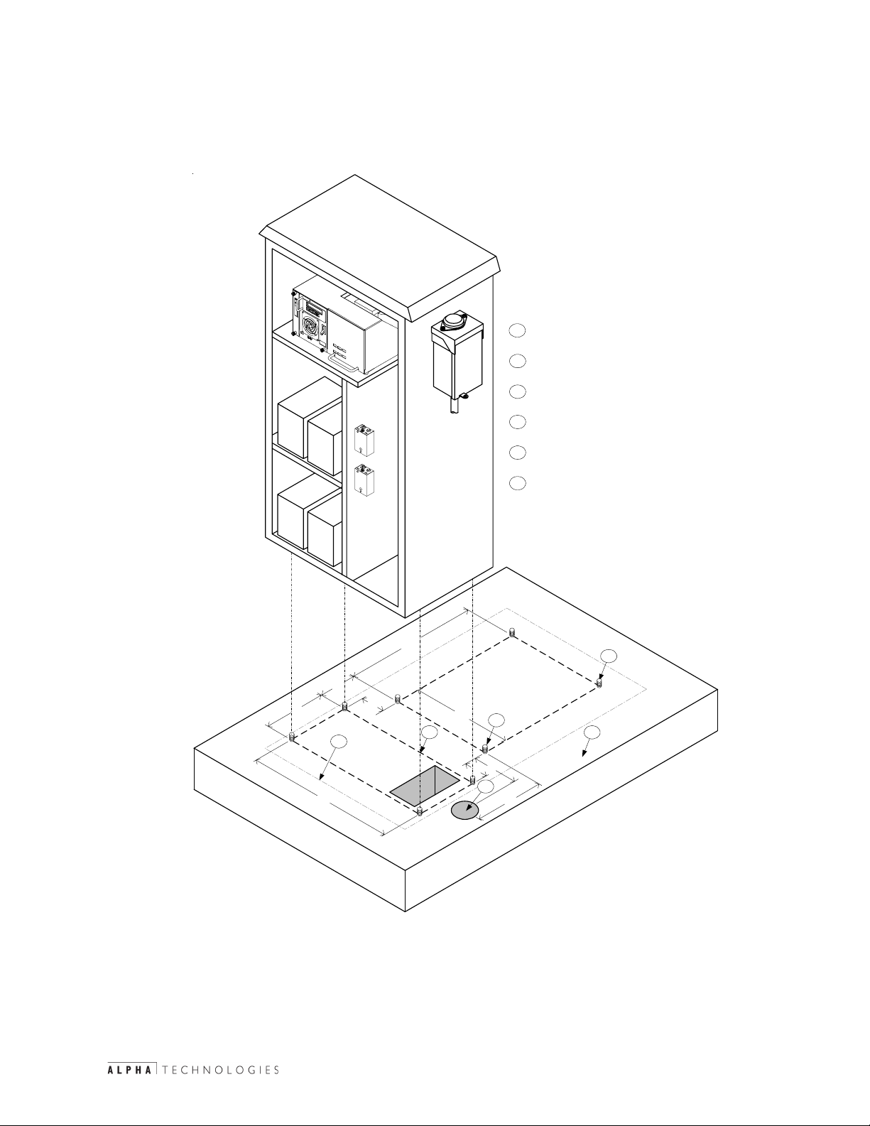
2.1 Concrete Pad Preparation
Pads can either be poured on site, or precast by Alpha Technologies. The mounting
holes on the bottom of the side car will fit both a standard PN-3 pad, and a CE3X pad.
Precast pad model number PCD-SC-3X, Alpha P/N 641-064-10 is available for this
system.
All measurements indixed to the
1
left-front generator mounting stud
Indicates enclosure mating
2
surface
Alpha standard, recomended distance,
3
between edge of pad and enclosure
4" diameter through-hole for AC Power
4
sweep (non-metered installation)
All mounting hardware must be stainless
5
or galvanized to prevent corrosion
5" X 8" cutout for internal connections
6
to generator, and coaxial cable sweeps
19.5
5.5
2
3.5
6
CESC-3X
9.2
22.0
14.7
Generator
6.8
3.5
4
1
10.25
5
3
All Measurments
in Inches
A 25+ year continuous vapor barrier must be used between the enclosure
and the pad to prevent moisture ingress and possible corrosion caused by
metal to concrete contact. The vapor barrier material (such as 30 lb felt,
neoprene pond liner, or heavy grade tar paper) must be initially extended at
least 6" in all directions around the perimeter of the enclosure. After the
enclosure is secured to the pad, the material can be cut closer to the
enclosure, using the appropriate knife or cutting tool.
© 2002
TM
5
031-099-C1-001 Rev. A
Page 6
2. Installation
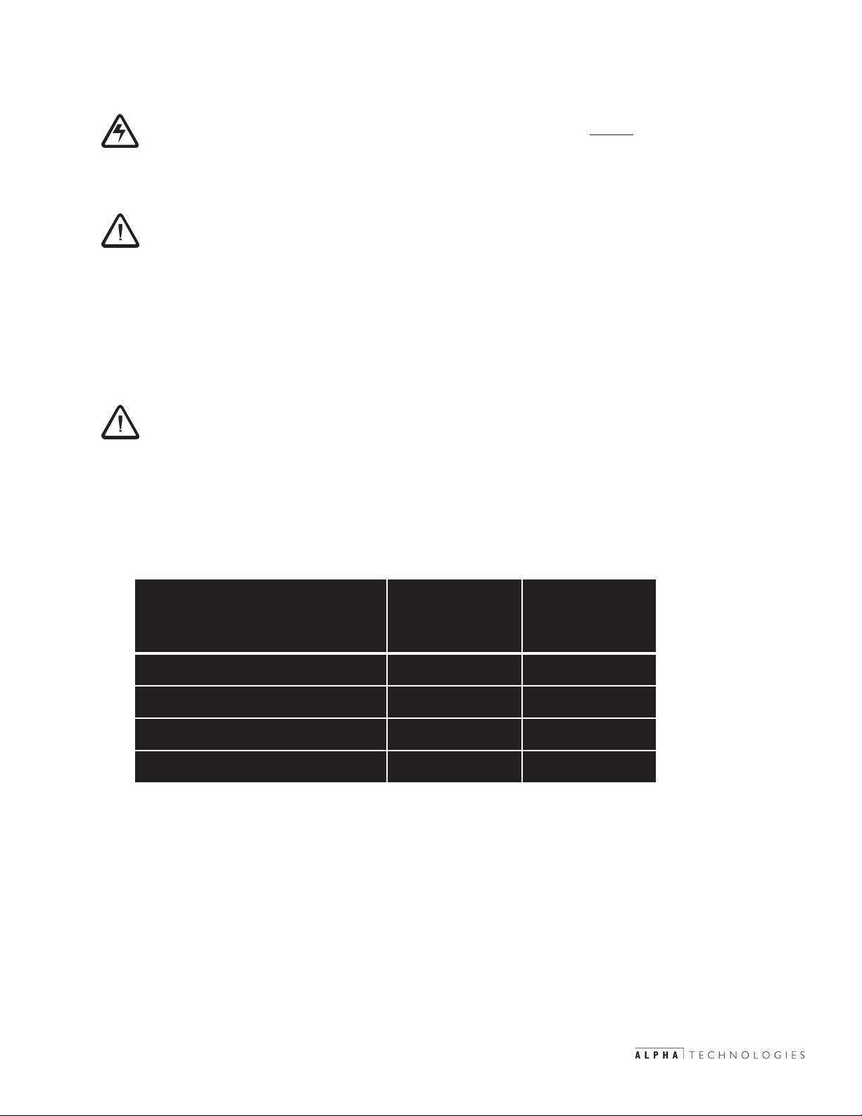
2.2 Utility Power Connection
CAUTION: The “Utility Power Connection” procedure must ONLY be
NOTE: UL and NEC require that a service disconnect switch (UL listed) be
Wiring the Utility Service
Utility power enters the enclosure through the side or bottom of the UPE. The
enclosure accepts a standard electrical fitting. The UPE Series can be equipped with an
optional circuit breaker assembly located in the enclosure’s module compartment.
NOTE: A “high-magnetic” trip circuit breaker must be used in order to
performed by qualified service personnel and in compliance
with local electrical codes and common safety practices.
Connection to utility power must be approved by the local
utility before installing the power supply.
provided by the installer and be connected between the power
source and the ALPHA power supply. Connection to the power
supply must include an appropriate service entrance weather head.
accommodate the high-inrush currents normally associated with the
start-up of ferroresonant transformers (400 Amp, no-trip, first-half
cycle). Do not replace this circuit breaker with a conventional service
entrance circuit breaker. Alpha recommends Square D circuit breakers
ONLY, because of increased reliability in this powering application.
Alpha Technologies offers a high-magnetic Square D circuit breaker and a BBX option (a
UL Listed service entrance). Contact your local sales representative for more information.
ahplA
DerauqS
noitpircseD
rebmuNtraP
)A51(citengaMnoN-noitallatsnIV042 01-422-074 5120Q
)A02(citengaMhgiH-noitallatsnIV021 01-710-074 MH9210Q
)A51(citengaMhgiH-noitallatsnIV021 01-310-074 MH5110Q
tcennocsiDecivreSlanretxE-XBB 01-580-020 BR07L4-20Q
Table 2-1; Service Entrance Circuit Breaker Requirements
In most cases, the following configurations (see next page) qualify for service
entrance use, however, other codes may apply. Always contact your local utility to
verify that the wiring conforms to applicable codes.
rebmuNtraP
031-099-C0-001 Rev. A
6
© 2000
TM
Page 7

2. Installation
2.2 Utility Power Connection, continued
240VAC Service (XM Series 2 915-240 Power Supply; XM Series 2 922-
48 for UPE-4 and UPE-8): Enclosures used with the XM
Series 2 915-240 or 922-48 are equipped with a 240VAC
duplex receptacle to provide power to the power supply
and peripheral equipment. The receptacle, NEMA 615R, is protected by a single, 2-pole, common trip 15
Amp circuit breaker located inside the service entrance.
Wiring is typically 14AWG per NEC code, a grounding
clamp, located on the enclosure, facilitates dedicated
grounding.
120VAC 20A Service (XM Series 2 915-120 Power Supply): Enclosures used
with the XM Series 2 915-120 are equipped with a
120VAC duplex receptacle to provide power to the
power supply and peripheral equipment. The receptacle,
NEMA 5-20R, is protected by a single, 2-pole, common
trip 20 Amp circuit breaker located inside the service
entrance. Wiring is typically 12AWG per NEC code, a
grounding clamp, located on the enclosure, facilitates
dedicated grounding.
120VAC 15A Service (XM Series 2 615): Enclosures used with the XM Series
2 615 are equipped with a 120VAC duplex receptacle
to provide power to the power supply and peripheral
equipment. The receptacle, NEMA 5-15R, is protected
by a single-pole, 15 Amp High Magnetic circuit breaker
located inside the service entrance. Wiring is typically
14AWG per NEC code, a grounding clamp, located on
the enclosure, facilitates dedicated grounding.
NOTE: Alpha recommends wiring with 12AWG, in case the enclosure
is to be upgraded to use 90V power supplies in the future.
© 2000
TM
7
031-099-C1-001 Rev. A
Page 8

2. Installation
2.2 Utility Power Connection, continued
ISE 120 VAC 15 Amp
Neutral
Ground
Line
ON
OFF
Neutral
Ground
Line
ISE 120 VAC 20 Amp
Ground
Line 2
Line 1
ISE 240 VAC 15 Amp
ON
OFF
ON
OFF
031-099-C0-001 Rev. A
8
© 2000
TM
Page 9

2.2 Utility Power Connection, continued
2. Installation
Ground
120 VAC Service
Entrance
From Utility
NeutralLine 1
ON
OFF
To Enclosure
240 VAC Service
Entrance
ON
OFFONOFF
NeutralLine 1Line 2Ground From Utility
To Enclosure
© 2000
TM
9
031-099-C1-001 Rev. A
Page 10

2. Installation
2.2 Utility Power Connection, continued
GroundLine 2Neutralline 1
ON
2
0
OFF
240 VAC Meter Base
GroundNeutralline 1
ON
OFF
031-099-C0-001 Rev. A
120 VAC Meter Base
10
© 2000
TM
Page 11

2. Installation
2.3 Generator / Sidecar Inter-connecting Cables
The following cables must be routed either through a 3" sweep or coupling:
#4 AWG DC Output from the generator
120 VAC power from the CESC sidecar service entrance
ECM or ACU Interface cable
Sidecar
Enclosure
Back Wall
Generator
Enclosure
Side Wall
3" PVC
Coupling
ECM Interface
Line
Neutral
120 VAC From Service Entrance
Ground
Positive
DC Output From Generator
Negative
© 2000
TM
11
031-099-C1-001 Rev. A
Page 12

2. Installation
2.4 Internal Components
A cooling fan is required any time a
Power Supply is housed in the side car.
The fan is thermostatically controlled to
turn on at 140 deg F and off at 110 deg
F. The fan cable has a 'T' connector
that attaches to the Power Supply
output connection. Replace fuse only
with a 1/4” X 1-1/4”, 5 Amp, 250 Volt
(Alpha P/N 460-025-10).
Cooling Fan
Thermostat
The Sidecar enclosure contains an
Input Power Panel (IPP), one or two
Service Power Inserters (SPI),and the
Enclosure Grounding Rail. The Power
Supply rests on the upper shelf, and a
48 VDC battery pack on the lower two
shelves.
Input Power Panel (IPP)
AC Power Connections
Fuse
Enclosure
Grounding Rail
SPI
031-099-C0-001 Rev. A
12
© 2002
TM
Page 13

2.5 Battery Pack Wiring
2. Installation
1
2
4
3
48 Volt
Battery Pack
Upper Shelf
1
3
Lower Sheff
2
36 Volt
Battery Pack
© 2000
TM
13
031-099-C1-001 Rev. A
Page 14

2. Installation
2.6 Power Supply Placement
1. Place the XM2 power supply onto the top shelf of the side car.
2. Verify that the AC Input Breaker in the service entrance is in the OFF position.
3. Verify that the Battery Breaker on the front of the power supply is in the OFF
position.
4. Plug the AC power cord into the Input Power Panel on the side of the enclosure.
5. Plug the Battery Input Cable from the battery pack into the Battery Input
connection on the front of the power supply.
6. Plug the wire leading from the fan into the OUTPUT 1 connection on the front of
the power supply.
7. Plug the wire leading from the top SPI into the other set of plugs on the wire
from the fan.
8. If a second SPI is installed, plug it into the OUTPUT 2 connection on the front of
the power supply.
Output to SPI
and Fan
XM2 Power Supply
AC Power Cord
Battery Pack Input
031-099-C0-001 Rev. A
14
© 2002
TM
Page 15

2. Installation
2.7 Battery Remote Temperature Sensor (RTS)
Tools Needed:
Adhesive Tape
Procedure:
For enclosures with multiple battery strings, the RTS must be located
with the WARMEST battery string. This ensures proper operation of
the battery charger’s temperature compensation circuit. Failure to
locate the RTS with the warmest battery string could result in
overcharging and premature battery failure. In this application, the RTS
MUST be attached to a battery in the upper tray of the side-car.
1. Attach the RTS Probe to the inner side of one of the batteries
on the upper tray of the side-car with adhesive tape.
2. The other side of the RTS Probe is attached to the front panel of the
XM2 power supply, in the jack labeled TEMP PROBE
© 2002
TM
15
031-099-C1-001 Rev. A
Page 16

2. Installation
2.8 Service Power Inserter
1. The SPI box(es) are mounted on the shelf support bracket.
2. Remove the two screws on the face of the SPI and lift off
the cover to gain access to the Seizure Screw Assembly.
Loosen the Seizure Screw several turns so that the stinger
will pass through the clamp. (Fig 2-3)
3, Insert the Coaxial Termination into the output
port on the bottom of the SPI. Ensure that the
stinger goes through the Seizure Screw Assembly.
Tighten the Coaxial Termination.
4. Tighten the seizure screw to 35.0 Inch-Pounds.
Replace the SPI cover and screws.
Ensure that the switch on the top or the SPI is
in the ON position, the AUX position is used only
when an alternate power source is connected to
the 'Jones" connector on the top of the SPI.
031-099-C0-001 Rev. A
Seizure Screw
Assembly
16
Seizure
Screw
© 2002
Coax
Stinger
Coax
Terminati on
TM
Page 17

Page 18

Investigate the of Alpha @ www.alpha.com
®
UNITED STATES
ASIA PACIFIC
LATIN AMERICA
Alpha Technologies
3767 Alpha Way
Bellingham, WA 98226
Tel: (360) 647-2360
Fax: (360) 671-4936
Web: www.alpha.com
CANADA
Alpha Technologies
4084 McConnell Ct.
Burnaby, B.C. V5A 3N7
Tel: (604) 430-1476
Fax: (604) 430-8908
UNITED KINGDOM
Alpha Technologies
Cartel Business Estate
Edinburgh Way
Harlow, Essex CM20 2DU
Tel: +44-1279-422110
Fax: +44-1279-423355
GERMANY
Alpha Technologies
Hansastrasse 8
D-91126 Schwabach
Tel: +49-9122-79889-0
Fax: +49-9122-79889-21
MIDDLE EAST
Alphatec
P.O. Box 6468
3307 Limassol, Cyprus
Tel: +357-5-375675
Fax: +357-5-359595
AUSTRALIA
Alpha Technologies
8 Anella Ave., Unit 6
Castle Hill, NSW 2154
Tel: +61 (0)2 9894-7866
Fax: +61 (0)2 9894-0234
TM
Copyright © 2000 Alpha Technologies, Inc. All rights reserved. Alpha is a registered trademark of Alpha Technologies. 031-099-C0-001 Rev. A
Due to continuing product improvements, Alpha reserves the right to change specifications without notice.
 Loading...