

Page 1
BSM-3 Battery Side Module Enclosure
Field Upgrade Installation
Effective: May, 2003
Manual
®
Page 2

Alpha Technologies
Power
®
Page 3
BSM-3
Battery Side Module
Field Installation Manual
033-082-C0-002, Rev. B
May, 2003
Copyright © 2003 by
Alpha Technologies, Inc
Preface
NOTE: Alpha denies responsibility for any damage or injury involving its
enclosures, power supplies, generators, batteries, or other
hardware when used for an unintended purpose, installed or
operated in an unapproved manner, or improperly maintained.
NOTE: Photographs contained in this manual are for illustrative purposes
only. These photographs may not exactly match your installation.
NOTE: Review the drawings and illustrations contained in this manual
before proceeding. If there are questions regarding the safe
operation of this powering system, please contact Alpha
Technologies or your nearest Alpha representative.
Contacting Alpha Technologies:
For general product information and customer service
1-800-863-3930
(7:00 AM to 5:00 PM Pacific Time )
033-082-C0-002 Rev. B
For complete technical support
1-800-863-3364
(7:00 AM to 5:00 PM Pacific Time, or 24/7 emergency support)
3
Page 4

Preface
Table of Contents
Preface Safety Instructions ..................................................... 5
Preface Safety Precautions ..................................................... 6
Preface Battery Safety Notes .................................................. 7
Preface Installation Notes ....................................................... 8
1.1 BSM Installation ......................................................... 1 0
1.2 Tamper Switch Option ................................................. 14
1.3 Enclosure Cooling Fan ................................................. 16
1.4 Insulation Placement .................................................. 17
1.5 Battery Installation ..................................................... 18
1.6 Part Numbers ............................................................ 2 2
List of Figures
Fig 1-1 Mounting Hole Location ........................................................... 11
Fig 1-2 Weather Strip Application ........................................................ 12
Fig 1-3 Tamper Switch Installation/Replacement .................................... 15
Fig 1-4 Fan Kit ................................................................................. 16
Fig 1-5 Insulation Placement .............................................................. 17
Fig 1-6 RTS Placement ...................................................................... 20
Fig 1-7 Battery Pack Wiring ................................................................ 21
4
033-082-C0-002 Rev. B
Page 5
Preface
Important Safety Instructions Contained In This
Manual Read This Manual Before Proceeding!
Review the drawings and illustrations contained in this manual before proceeding. If there are any questions
regarding the safe installation or operation of the system, contact Alpha Technologies or the nearest Alpha
representative. Save this document for future reference.
To reduce the risk of injury or death caused by electrical shock, explosion of fuel or moving parts; and to ensure the
continued safe operation of this product, the following symbols have been placed throughout this manual. Where
these symbols appear, use extra care and attention.
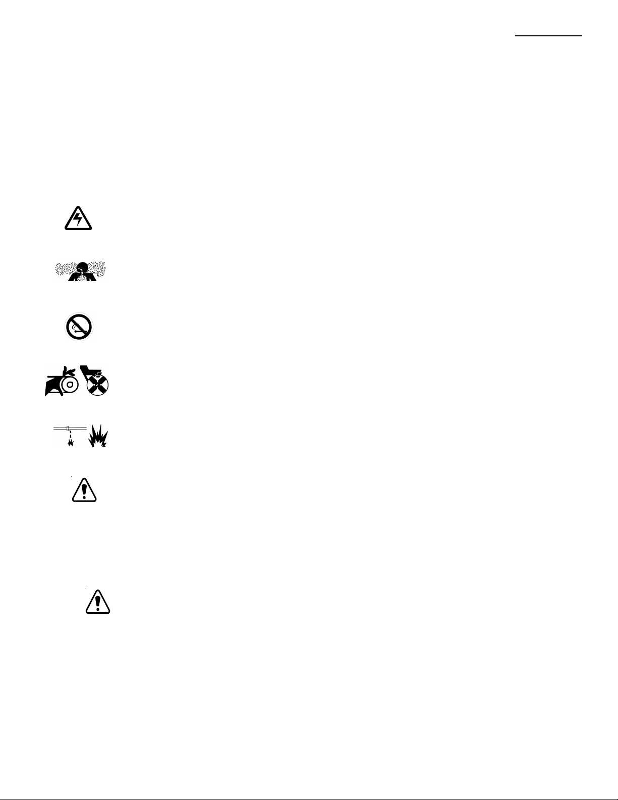
DANGEROUS VOLTAGE
This symbol indicates a “dangerous voltage” may exist in this area of the product. Use caution whenever
working in the area to prevent electrical shock.
INHALATION HAZARD - DON’T BREATHE VAPORS
This symbol indicates an “inhalation hazard” may exist in this area of the product. Use caution whenever
working in the area to prevent possible inhalation of harmful (fuel or exhaust) vapors.
NO MATCHES OR OPEN FLAMES
This symbol indicates a “fire or explosive hazard” may exist in this area of the product. Use caution
whenever working in the area to prevent possible combustion of fuel vapors.
MECHANICAL OR MOVING PARTS HAZARD
These symbols indicate a “mechanical or moving parts hazard” may exist in this area of the product.
Use caution whenever working in the area to prevent possible injury to the operator or service personnel.
LEAK HAZARD
This symbol indicates a “leak hazard” may exist in this area of the product. Use caution whenever
working in this area to prevent and correct any leaks detected.
ATTENTION
This symbol indicates important installation, operation or maintenance instructions. Always follow
these instructions closely.
NOTE: Alpha Technologies’ products are subject to change through continual
improvement processes. Therefore, specifications and/or design layouts
may vary slightly from descriptions included in this manual. Updates to
the manual will be issued when changes affect form, fit or function.
033-082-C0-002 Rev. B
5
Page 6

Preface
General Safety Precautions
A “Warning” identifies conditions and actions that pose a hazard to the user.
A “Caution” identifies conditions and actions that may damage the power supply or
associated equipment.
Warnings
NOTE: This enclosure and its associated hardware (power supply, batteries, cabling)
may contain equipment, batteries or parts which have accessible hazardous
voltage or currents.
To avoid injury
• This enclosure and its associated hardware must be serviced by authorized personnel only.
• Enclosure must remain locked at all times, except when authorized service personnel are
present.
• Remove all conductive jewelry or personal equipment prior to servicing equipment, parts,
connectors, wiring, or batteries.
• Read and follow all installation, equipment grounding, usage, and service instructions included in
this manual.
• Use proper lifting techniques whenever handling enclosure, equipment, parts, or batteries.
• Batteries contain dangerous voltages, currents and corrosive material. Battery installation,
maintenance, service and replacement must be performed by authorized personnel only.
• Never use uninsulated tools or other conductive materials when installing, maintaining, servicing
or replacing batteries.
• Use special caution when connecting or adjusting battery cabling. An improperly connected
battery cable or an unconnected battery cable can result in arcing, a fire, or possible explosion.
• A battery that shows signs of cracking, leaking or swelling must be replaced immediately by
authorized personnel using a battery of identical type and rating.
:
• Avoid any contact with gelled or liquid emissions from a valve-regulated lead-acid (VRLA) battery.
Emissions contain dilute sulfuric acid which is harmful to the skin and eyes. Emissions are
electrolytic, which are electrically conductive and are corrosive. Follow the Chemical Hazards
notes if contact occurs.
• Do not smoke or introduce sparks in the vicinity of a battery.
• Under certain overcharging conditions, lead-acid batteries can vent a mixture of hydrogen gas
which isexplosive. Proper venting of the enclosure is required.
• Follow the battery manufacturer’s approved transportation and storage instructions.
6
033-082-C0-002 Rev. B
Page 7

Preface
Battery Safety Notes
Lead-acid batteries contain dangerous voltages, currents and corrosive material. Battery installation,
maintenance, service and replacement must be performed by authorized personnel only.
Chemical Hazards
NOTE: Any gelled or liquid emissions from a valve-regulated lead-acid (VRLA) battery
contain dilute sulfuric acid, which is harmful to the skin and eyes. Emissions are
electrolytic, which are electrically conductive and corrosive.
To avoid injury:
• Servicing and connection of batteries shall be performed by, or under the direct supervision of,
personnel knowledgeable of batteries and the required safety precautions.
• Always wear eye protection, rubber gloves, and a protective vest when working near batteries.
Remove all metallic objects from hands and neck.
• Batteries produce explosive gases. Keep all open flames and sparks away from batteries.
• Use tools with insulated handles, do not rest any tools on top of batteries.
• Batteries contain or emit chemicals known to the State of California to cause cancer and birth
defects or other reproductive harm. Battery post terminals and related accessories contain
lead and lead compounds. Wash hands after handling. (California Proposition 65)
• Wear protective clothing (insulated gloves, eye protection, etc) whenever installing,
maintaining, servicing, or replacing batteries.
• If any battery emission contacts the skin, wash immediately and thoroughly with water. Follow
your company’s approved chemical exposure procedures.
• If any battery emission contacts the eye, wash immediately and thoroughly with water for 10
minutes with pure water or a special neutralizing eye wash solution and seek immediate
medical attention. Follow your company’s approved chemical exposure procedures.
• Neutralize any spilled battery emission with the special solution contained in an approved spill
kit or with a solution of 1 lb. Bicarbonate of soda to 1 gal of water. Report chemical spill using
your company’s spill reporting structure and seek medical attention if necessary.
• Always replace batteries with those of an identical type and rating. Never install old or
untested batteries.
• Do not charge batteries in a sealed container. Each individual battery should have at least 0.5
inches of space between it and all surrounding surfaces to allow for convection cooling.
033-082-C0-002 Rev. B
• All battery compartments must have adequate ventilation to prevent an accumulation of
potentially dangerous gas.
7
Page 8

Preface
Battery Safety Notes,
• Prior to handling the batteries, touch a grounded metal object to dissipate any static charge that
may have developed on your body.
• Never use uninsulated tools or other conductive materials when installing, maintaining, servicing
or replacing batteries.
• Use special caution when connecting or adjusting battery cabling. An improperly connected
battery cable or an unconnected battery cable can make contact with an unintended surface that
can result in arcing, fire, or possible explosion.
• A battery showing signs of cracking, leaking, or swelling should be replaced immediately by
Authorized Personnel using a battery of identical type and rating.
• Under extreme overcharging conditions, Lead-acid batteries can vent a mixture of Hydrogen gas
which is explosive.
continued
Battery Maintenance Guidelines
The battery maintenance instructions listed below are for reference only. Battery manufacturer’s
instructions for transportation, installation, storage or maintenance take precedence over these
instructions.
• To prevent damage, inspect batteries every 3 months for:
Signs of battery cracking, leaking or swelling.
authorized personnel using a battery of the identical type and rating.
Signs of battery cable damage.
Personnel using replacement parts specified by vendor.
Loose battery connection hardware.
correct torque and connection hardware for the application.
• Apply battery manufacturer’s specified antioxidant compound on all exposed connections.
• Verify battery terminals and/or exposed connection hardware is not within 2 inches of a
conductive surface. Reposition batteries as necessary to maintain adequate clearance.
• Clean up any electrolyte (battery emission) in accordance with all federal, state, and local
regulations or codes.
• Proper venting of the enclosure is recommended. Follow the Battery Manufacturer’s approved
transportation and storage instructions.
• Always replace batteries with those of an identical type and rating. Never install old or
untested batteries.
Battery cable should be replaced immediately by Authorized
Refer to battery manufacturer’s documentation for the
The battery should be replaced immediately by
8
033-082-C0-002 Rev. B
Page 9

Recycling and Disposal Instructions
• Spent or damaged batteries are considered environmentally unsafe. Always recycle used
batteries or dispose of the batteries in accordance with all federal, state and local regulations.
Electrical Safety
• Lethal voltages are present within the power supply and electrical boxes. Never assume
that an electrical connection or conductor is not energized. Check the circuit with a volt
meter with respect to the grounded portion of the enclosure (both AC and DC) prior to any
installation or removal procedure.
• Do not work alone under hazardous conditions.
• A licensed electrician is required to install permanently wired equipment.
• Input voltages can range up to 240 VAC. Ensure that utility power is disabled before beginning
installation or removal.
Preface
• Ensure no liquids or wet clothes contact internal components.
• Hazardous electrically live parts inside this unit are energized from batteries even when the
AC input power is disconnected from the Mini-Bay.
Mechanical Safety
• Keep hands and tools clear of fans. Fans are thermostatically controlled and will turn on
automatically.
• Power supplies can reach extreme temperatures under load.
• Use caution around sheet metal components and sharp edges.
033-082-C0-002 Rev. B
9
Page 10

1. Installation
1.1 BSM Installation
Overview
The Battery Side Module was designed to allow the customer to add
additional batteries in the field for additional standby/run time. The
BSM-3 was designed for use with the UPE-M3 enclosure only.
WARNING: DO NOT install a BSM-3 on both sides of the UPE-M3,
or install a second power supply in the UPE-M3, to do
so will void your warranty and result in thermal
damage to the power supply and battery packs.
Upon receipt, the enclosure should be unpacked and inspected for
shipping damage. The following items should be enclosed:
1. BSM-3 Enclosure and door, with two
sets of keys.
2. 6 aluminum rivets and 2 sets of #10 nuts and
bolts for mounting the BSM-3.
3. Battery cable conduit, consisting of a chase
nipple, lock washer and bushing.
4. Self adhesive insulation pads, and weather stripping.
5. Battery Cable Kit (Alpha P/N 874-479-22).
1.1.1. Enclosure Preparation
Tools and Materials Needed:
Center Punch or Permanent Marker
Tape measure
Electric or pneumatic drill
No. 7 drill bit (.203”)
#2 Phillips screw driver
Hand operated rivet gun with .188” nosepiece
Drill-stop collar for No. 7 drill bit
Hole saw or hydraulic punch for 1.375” hole
Wet-dry vacuum
Utility knife
1” Chase nipple (supplied)
1” locknut (supplied)
1” plastic bushing (supplied)
Enclosure Cooling Fan Kit (if not previously installed)
6 aluminum rivets (supplied)
2 #10-32 x 3/4” pan-head screws (supplied)
2 #10-32 Nuts (supplied)
4 #10 Paint-Break washers (supplied)
Procedure:
10
NOTE: Metal shavings will enter the UPE-M3 enclosure during this
procedure. Before proceeding, verify that the power supply, CB
box, Service Entrance and batteries are disconnected and
protected.
033-082-C0-002 Rev. B
Page 11

1.1 BSM Installation, continued
1.1.1. Enclosure Preparation, continued
1. Installation
WARNING:
Follow all manufacturer’s operating and safety
instructions for the use of power tools and punch
drivers
1. Place the Battery Side Module (BSM) on the pad beside the
UPE-M3 enclosure (Fig. 1-1). Slide the BSM-3 against the side of
the UPE-M3, ensuring that the top edge of the BSM-3 rests
between the rows of louvers.
2. Using the holes in the inside flange of the BSM-3 as a template,
mark the eight holes on the UPE-M3 enclosure with a punch or
marker. Mark the location of the 1.375” cable conduit hole.
Cable Conduit
Hole
35.8
26.8
15.8
6.8
0.6
2
Fig 1-1 Mounting Hole Locations
0.6
12.5
0.200
O
8X
11033-082-C0-002 Rev. B
Page 12

1. Installation
1.1 BSM Installation, continued
1.1.1. Enclosure Preparation, continued
3. Install weather stripping (included) to the mounting surfaces of
the BSM-3, as shown below. Ensure stripping meets to form a
water tight seal at the top corners. Do not apply weather
stripping to the bottom edge of the BSM-3.
12
Fig 1-2 Weather Strip Application
033-082-C0-002 Rev. B
Page 13

1.1 BSM Installation, continued
1.1.1. Enclosure Preparation, continued
CAUTION: Do not drill through the inner wall of the UPE-M3
when drilling the upper rivet holes. Doing so will
violate E.U.S.E.R.C. code.
4. Using No. 7 drill bit, with Drill-Stop collar set 1” from drill tip,
drill the holes marked in step 2.
6. Using a hole saw or punch driver, drill the 1.375” hole for the
cable conduit marked in step 2.
7. Use a utility knife or de-burring tool to remove any sharp edges
from around conduit hole.
8. Place the BSM-3 into position, and align the holes.
1. Installation
NOTE: To provide proper grounding, two of the rivet holes must
be filled with stainless steel screws and nuts, with paintbreak washers against the enclosures, as shown below.
The bottom set of holes are recommended.
9. Rivet and bolt the BSM-3 into place using the aluminum rivets
and stainless steel hardware provided. See diagram Below.
Weather
Striping
BSM
Mounti ng
Flange
UPE-M
Enclosure
Side-Wall
BSM
Mountin g
Flange
10. Install the 1” chase nipple, locknut and bushing into the 1.375”
conduit hole, as shown below.
Chase
Nipple
UPEM
Wall
Lock
Nut
Bushing
Weather
Striping
UPE-M
Enclosure
Side-Wall
Paint-Break
Washers
11. Vacuum the metal shavings from the UPE-M3 and the BSM-3.
13033-082-C0-002 Rev. B
Page 14

1. Installation
1.2 Dual Tamper Switch Option
1.2.1. Tamper Switch Installation
The Dual Tamper Switch option allows the USM2 or USM2.5 Communications
Card to monitor both the UPE-M3 door and the BSM-3 door.
Tools and Materials Needed:
#2 Phillips Screwdriver
5/16” Nut Driver
4 Sheet metal screws (supplied)
4 #6-32 nuts (supplied)
4 #6 Lock washers (supplied)
Dual pre-wired tamper switch harness (supplied)
Procedure:
1. If installed, unplug the existing tamper switch connector from the
front of the power supply in the UPE-M3 enclosure.
2. If installed, use a screwdriver to remove the wired portion of the
tamper switch, located on the front left corner of the power supply
shelf. Remove switch and wiring from the enclosure.
3. Route the new tamper switches and connector through the cable
conduit between the UPE-M3 and BSM-3 enclosures.
See Fig. 1-3 (A), on the following page.
4. Using the predrilled holes, install the new tamper switch on the
left side of the power supply shelf in the UPE-M3 and on the upper
left door jamb in the BSM-3, using the sheet metal screws and lock
washers provided in the tamper switch kit. See Fig. 1-3 (C)
5. If not previously installed, attach the magnet portion of the tamper
switches to the studs on the doors directly opposite the switch,
with the #6-32 nuts and lock washers included in the tamper
switch kit. See Fig. 1-3 (B).
6. Connect the tamper switch cable connector to the jack on the
front of the power supply labeled TMPR. See Fig. 1-3 (A).
7. Secure the tamper switch wires so that they will not be damaged
by the doors or sliding trays.
14
033-082-C0-002 Rev. B
Page 15

1.2 Dual Tamper Switch Option, continued
1.2.1. Tamper Switch Installation, continued
BSM-3 Tamper
A
Route through
conduit
Switch
UPE-M3
Tamper Switch
1. Installation
'TMPR'
connection
#6-32
Nut
Lock
Washer
Magnet
(side View)
Sheet Metal
Screw
Enclosure
Door
Mounting
Stud
Lock
Washer
(side View)
B
Fig 1-3 Tamper Switch Replacement / Installation
Switch
Door Frame
or Shelf
Pre-Drilled
Hole
C
15033-082-C0-002 Rev. B
Page 16

1. Installation
1.3 Enclosure Cooling Fan
1.3.1. Cooling Fan
Tools and Materials Needed:
3/8” Nut-driver or open end wrench
UPEM Fan Kit (Alpha P/N 744-797-24)
Procedure:
CAUTION: Due to restricted air flow, an enclosure cooling fan
MUST be installed in the UPE-M3 enclosure when
using a Battery Side Module.
Enclosure
Cooling Fan
SPI
Fig 1-4 Fan Kit
Refer to the UPEM Series installation manual (P/N 031-145-C0) for detailed
instructions on installing the fan kit.
16
033-082-C0-002 Rev. B
Page 17

1.4 Insulation Installation
1.4.1. Insulation Pad Placement
Tools and Materials Needed:
Foam insulation (supplied)
Utility knife
Procedure:
CAUTION: To prevent thermal overload of the power supply
and batteries, an insulating pad MUST be placed in
the power supply compartment of the UPEM enclosure.
1. Insulation pads are pre-cut to proper size. When installing on the left
side of the enclosure, use the 12” X 13.5” pad. When installing on
the right, use the 7” X 13.5” pad. Insulate only the side facing the
BSM-3.
2. Peel the cover off the adhesive, and place against the side of
the enclosure, as shown below. Dispose of unused insulation pad.
1. Installation
Place insulation pad
here when BSM is
mounted on the right
13.5"
BSM-3 mounted on the right
BSM-3 mounted on the left
Place Pad Here
7"
12"
Place Pad Here
Place insulation pad
here when BSM is
mounted on the left
13.5"
Fig 1-5 Insulation Placement
17033-082-C0-002 Rev. B
Page 18

1. Installation
1.5 Battery Installation
Each battery contains a DATE CODE usually located on a sticker near the center of
the battery or stamped in white ink near the POS terminal. This date code must be
recorded in the battery’s maintenance log. If batteries other than those installed by
Alpha are used, consult the battery’s manufacturers’ documentation for date code
type and placement.
1.4.1. Date Code
DANGER/POISON
SHIELD EYES EXPLOSIVE GASES
CAN CAUSE BLINDNESS OR INJURY
NO SPARKS, FLAMES, OR SMOKING
SULFURIC ACID CAN CAUSE
BLINDNESS OR SEVERE BURNS
CALIF. PROPOSITION 65
WARNING
Battery posts, terminals
and related accessories
contain lead and lead
compounds, chemicals
known to the state of Calif.
to cause cancer and
reproductive harm. Wash
hands after handling.
MMYY
Battery Date Code
located in this box
(0103 = Jan. 2003)
FLUSH EYES IMMEDIATELY WITH WATER
GET MEDICAL HELP FAST. KEEP OUT OF REACH OF CHILDREN
1.4.2. Battery Terminals
The accompanying drawings are for illustrative purposes only. Various types of
batteries with different mounting styles and hardware may be shipped with the
system. ALWAYS refer to the battery manufacturers’ specifications for correct
mounting hardware and torque requirements. During maintenance procedures, refer
to the manufacturers' specifications for the maintenance torque requirements.
For AlphaCell batteries, use 65 Inch-Pounds upon installation, then re-torque to 50
Inch-Pounds during maintenance.
Mounting hardware requirements may vary with battery manufacturers. Use only the
hardware recommended by your particular battery manufacturer.
Battery Cable and
Crimp Connector to
Battery Post
3/8" Spacer
Flat Washer
Lock Washer
Nut
Fuse
Next Battery
18
033-082-C0-002 Rev. B
Page 19

1.5 Battery Installation, continued
1.5.1 Battery Connection
Tools and Materials Needed:
Two 7/16” open end wrenches
Battery Cable Kit, BSM-3 (Alpha P/N 874-497-22)
Procedure:
WARNING: Set the BATTERY BREAKER on the power
supply to OFF.
To prevent short circuits, route only ONE wire at a time
through the cable conduit. Attach the cable at both ends
before routing the second cable through.
1. Install 3 batteries into the BSM-3 as shown in Fig. 1-4
1. Installation
NOTE: When attaching cables to the battery pack in the
UPE-M3, place the termination on the opposite
side of the battery post from the existing wire.
UPE-M3
Battery
Cable
BSM-3
Battery
Cable
Co-Termination
Nut
Lock
Washer
MDG
2. Install the battery cable kit one wire at a time. Connect
both ends before installing the next wire to avoid short circuits.
3. Set the BATTERY BREAKER on the front of the power Supply to
the ON position
Bolt
Flat Washer
Batt ery Post
NOTE: If battery wires for status monitoring are to be
installed, refer to the transponder manufacturers
instructions for wiring diagrams. Install the fuse
in the location shown on the battery wiring
diagram.
19033-082-C0-002 Rev. B
Page 20

1. Installation
1.5 Battery Installation, continued
Battery Remote Temperature Sensor (RTS)
Tools Needed:
Adhesive Tape
Procedure:
1. Attach the RTS Probe to the inner side of the center battery
in the UPE-M3 enclosure with adhesive tape (see Fig. 1-4).
2. For enclosures with multiple battery strings, the RTS must be located
with the WARMEST battery string. This ensures proper operation of
the battery charger’s temperature compensation circuit. Failure to
locate the RTS with the warmest battery string could result in
overcharging and premature battery failure.
3. The other side of the RTS Probe is attached to the front panel of the
XM Series 2 power supply, in the UPE-M3 enclosure.
20
Fig. 1-6 Battery Remote Temp Sensor (RTS) placement
033-082-C0-002 Rev. B
Page 21

1.5 Battery Installation, continued
Fuse
Existing wiring not shown
for clarity
1. Installation
BSM-3
Battery Pack
Co-Terminate
with existing wire
Attach RTS here
Front of
Enclosure
Co-Terminate
with existing wire
UPE-M3
Battery Pack
UPE-M3
Battery Pack
Existing wiring not shown
for clarity
Co-Terminate
with existing wire
Attach RTS here
Co-Terminate
with existing wire
Fuse
Front of
Enclosure
Fig 1-7 UPE-M3 / BSM-3 Battery Pack
BSM-3
Battery Pack
21033-082-C0-002 Rev. B
Page 22

1. Installation
1.6 Part Numbers
BSM-3 Ground Mount Enclosure 033-082-20
BSM-3 Battery Cable Kit 874-479-22
BSM-3 Tamper Switch Kit 874-958-20
22
033-082-C0-002 Rev. B
Page 23

Page 24

Alpha Technologies
Power
®
Corporate
Alpha Technologies
3767 Alpha Way
Bellingham, WA 98226
USA
Tel: (360) 647-2360
Fax: (360) 671-4936
Web: www.alpha.com
Alpha Technologies Ltd.
4084 McConnell Court
Burnaby, BC, V5A 3N7
CANADA
Tel: (604) 430-1476
Fax: (604) 430-8908
Alpha Technologies
Europe Ltd.
Cartel Business Estate
Edinburgh Way
Harlow, Essex CM20 2TT
UNITED KINGDOM
Tel: +44-1279-422110
Fax: +44-1279-423355
Alpha Technologies
Hansastrasse 8
D-91126 Schwabach
GERMANY
Tel: +49-9122-79889-0
Fax: +49-9122-79889-21
Alphatec
339 St. Andrews Street
Suite 101
Andrea Chambers
Limassol, Cyprus
CYPRUS
Tel: +357-25-375675
Fax: +357-25-359595
Alpha Technologies
Unit R5-R7 Regents Park Estate
Corner Park Rd and Prince’s Rd East
Regents Park, NSW 2143
AUSTRALIA
Tel: +61-2-9722-3320
Fax: +61-2-9722-3321
Copyright © 2002 Alpha Technologies, Inc. All rights reserved. Alpha is a registered trademark of Alpha Technologies. 033-082-C0-002 Rev. B.
Due to continuing product improvements, Alpha reserves the right to change specifications without notice.
 Loading...