

Page 1
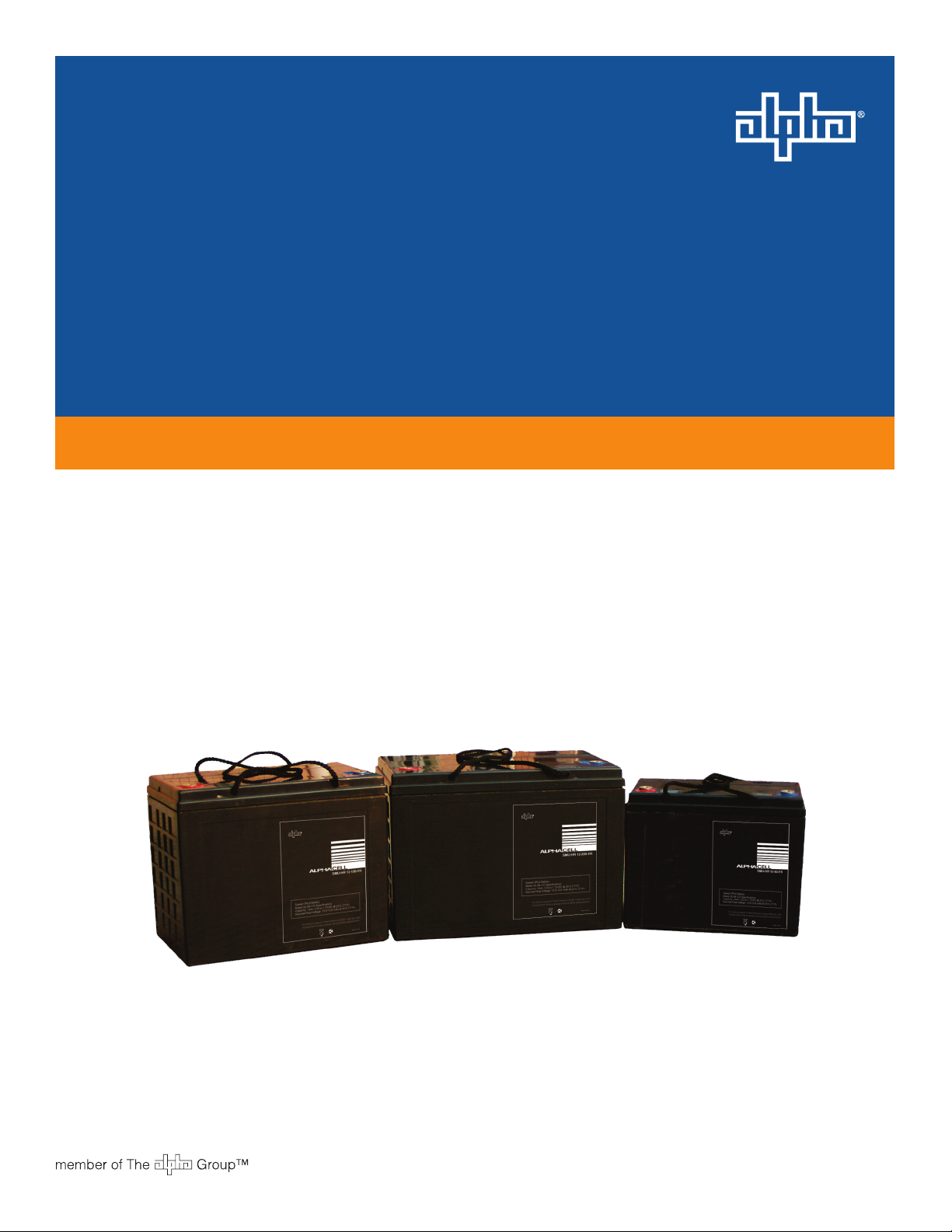
AlphaCellTM SMU-C Series Batteries
Technical Manual
Effective: December 2010
Page 2

Page 3
AlphaCellTM SMU-C Series Batteries
Technical Manual
745-680-B11-001 Rev. A
Effective Date: December, 2010
Copyright © 2010
Alpha Technologies, Inc.
member of The Group
NOTE:
Photographs contained in this manual are for illustrative purposes only. These photographs may not match
your installation.
NOTE:
Operator is cautioned to review the drawings and illustrations contained in this manual before proceeding. If
there are questions regarding the safe operation of this product, please contact Alpha Technologies or your
nearest Alpha representative.
NOTE:
Alpha shall not be held liable for any damage or injury involving its enclosures, power supplies, generators,
batteries, or other hardware if used or operated in any manner or subject to any condition not consistent with
its intended purpose, or is installed or operated in an unapproved manner, or improperly maintained.
TM
Contacting Alpha Technologies: www.alpha.com
OR
For general product information and customer service (7 AM to 5 PM, Pacic Time), call
1-800-863-3930,
For complete technical support, call
1-800-863-3364
7 AM to 5 PM, Pacic Time or 24/7 emergency support
745-680-B11-001, Rev. A
3
Page 4

Table of Contents
Safety Notes .......................................................................................................................... 6
Battery Safety Notes.............................................................................................................. 7
1.0 Introduction ................................................................................................................. 8
1.1 Features ........................................................................................................... 8
1.2 Typical Electrical and Mechanical Specications ............................................. 9
1.3 Operating Conditions ..................................................................................... 10
1.4 Capacity ......................................................................................................... 10
1.5 Temperature and Battery Life..........................................................................11
1.6 Internal Resistance and Short-circuit Current .................................................11
2.0 Charging Procedures ................................................................................................ 12
2.1 General Charge ............................................................................................. 12
2.2 Floating Charge ............................................................................................. 13
2.3 Discharge ....................................................................................................... 13
3.0 Storage ..................................................................................................................... 14
4.0 Maintenance ............................................................................................................. 15
4.1 Recommended Maintenance Tasks ............................................................... 15
5.0 Discharge Specications .......................................................................................... 17
5.1 Discharge Data with Constant Current .......................................................... 17
5.2 Discharge Data with Constant Power ............................................................ 23
6.0 Forms ........................................................................................................................29
6.1 Discharge Recording Form ............................................................................ 29
4
745-680-B11-001, Rev. A
Page 5

Figures
Fig. 1-1, Available Capacity vs. Ambient Temperature ........................................................ 10
Fig. 2-1, Charge Characteristics Curve ............................................................................... 12
Fig. 3-1, Capacity vs. Storage Time .................................................................................... 14
Fig. 4-1, VRLA Battery Regular Maintenance Record ......................................................... 16
Tables
Table 1-1, General Electrical and Mechanical Specications by Model ................................ 9
Table 1-2, Internal Resistance and Short Circuit Current at 77ºF (25ºC).............................11
Table 2-1, Floating Voltage at Different Temperatures.........................................................13
Table 2-2, Discharge End-Voltage ....................................................................................... 13
745-680-B11-001, Rev. A
5
Page 6
Safety Notes
Review the drawings and illustrations contained in this manual before proceeding. If there are any questions
regarding the safe installation or operation of the system, contact Alpha Technologies or the nearest Alpha
representative. Save this document for future reference.
To reduce the risk of injury or death, and to ensure the continued safe operation of this product, the following
symbols have been placed throughout this manual. Where these symbols appear, use extra care and
attention.
ATTENTION:
The use of ATTENTION is only for specic regulatory/code requirements that may affect the placement of
equipment and installation procedures.
NOTE:
A NOTE gives readers additional information to help them complete a specic task or procedure.
CAUTION!
The use of CAUTION indicates safety information intended to PREVENT DAMAGE to material or
equipment.
WARNING!
WARNING presents safety information to PREVENT INJURY OR DEATH to the technician
or user.
6
745-680-B11-001, Rev. A
Page 7

Battery Safety Notes
WARNING!
Lead-acid batteries contain dangerous voltages, currents and corrosive material. Battery
installation, maintenance, service and replacement must be performed only by authorized
personnel.
Chemical Hazards
Any gelled or liquid leakage from a valve-regulated lead-acid (VRLA) battery contains dilute sulfuric acid,
which is harmful to the skin and eyes. Emissions are electrolytic, and are electrically conductive and
corrosive.
To avoid injury:
Servicing and connection of batteries shall be performed by, or under the direct supervision of, personnel •
knowledgeable of batteries and the required safety precautions.
Always wear eye protection, rubber gloves, and a protective vest when working near batteries. Remove all metallic •
objects from hands and neck.
Batteries produce explosive gases. Keep all open ames and sparks away from batteries.•
Use tools with insulated handles, do not rest any tools on top of batteries.•
Lead-acid batteries contain or emit chemicals known to the State of California to cause cancer and birth defects or •
other reproductive harm. Battery post terminals and related accessories contain lead and lead compounds. Wash
hands after handling (California Proposition 65).
Wear protective clothing (insulated gloves, eye protection, etc.) when installing, maintaining, servicing, or replacing •
batteries.
If any battery emission contacts the skin, wash immediately and thoroughly with water. Follow your company’s •
approved chemical exposure procedures.
Neutralize any spilled battery emission with the special solution contained in an approved spill kit or with a solution •
of one pound bicarbonate of soda to one gallon of water. Report a chemical spill using your company’s spill reporting
structure and seek medical attention if necessary.
Always replace batteries with those of an identical type and rating. Never install old or untested batteries.•
Do not charge batteries in a sealed container. Each individual battery should have at least 0.5 inches of space •
between it and all surrounding surfaces to allow for convection cooling.
All battery compartments must have adequate ventilation to prevent accumulation of potentially dangerous gas. •
Ventilation should prevent trapped hydrogen gas pockets from exceeding a 1% concentration as per regulation 70E
of the National Fire Protection Agency (NFPA).
Prior to handling the batteries, touch a grounded metal object to dissipate any static charge that may have developed •
on your body.
Never use uninsulated tools or other conductive materials when installing, maintaining, servicing, or replacing •
batteries.
Use special caution when connecting or adjusting battery cabling. An improperly connected battery cable or an •
unconnected battery cable can make contact with an unintended surface that can result in arcing, re, or possible
explosion.
A battery showing signs of cracking, leaking, or swelling should be replaced immediately by authorized personnel •
using a battery of identical type and rating.
Equipment Cautions
Do not operate NiCd and lead-acid batteries in the same room. NiCd emissions will neutralize the lead-acid solution, •
rendering the battery useless.
Overcharging the battery can result in a loss of capacity and excess release of gas.•
Recycling and Disposal Instructions
Spent or damaged batteries are considered environmentally unsafe. Always recycle used batteries or dispose of the
batteries in accordance with all federal, state and local regulations.
745-680-B11-001, Rev. A
7
Page 8

1.0 Introduction
The SMU-C series of Valve Regulated Lead Acid (VRLA) batteries is designed to meet the needs of
modern electronic equipment. The success of the AlphaCell SMU-C series is due to a product design
purpose-built for the needs of critical backup requirements, and an industry-leading manufacturing
technology which delivers product consistency. Safety, reliability, and long service life in standby
applications are the result.
1.1 Features
Require no additional water throughout their life cycle, reducing maintenance costs. •
Specically designed to meet the requirements of modern electronic equipment. •
Compatible with commonly available recharging systems.•
Compact construction and excellent performance at high rates of discharge provide big •
savings in volume and weight compared to conventional vented batteries.
SMU-C batteries offer substantial savings in installation and maintenance costs •
compared to conventional vented batteries. No specically designed rooms are required
and only minimal maintenance is needed during the life of the battery.
Smaller, more compact, and lighter than traditional batteries, SMU-C batteries are •
supplied lled and charged so they can be immediately installed directly into cabinets or
on easily assembled racks (also available from Alpha).
With a minimum 10 year design life, the SMU-C batteries are highly reliable and fully •
comply with established international standards. The SMU-C range has been fully tested
with respect to charge and discharge characteristics, cycle life, recombination efciency,
mechanical strength, vibration life, and ame retardancy.
8
745-680-B11-001, Rev. A
Page 9

1.2 TypicalElectricalandMechanicalSpecications
Type
SMU-C 6-4.5 6 4.5 14.6 2.76 x 1.85 x 4.21 / 70 x 47 x 107 1.8 / .82
SMU-C 6-7 6 8.0 32.4 5.94 x 1.34 x 3.94 / 151 x 34 x 100 3.0 / 1.4
SMU-C 6-12 6 13.2 54.1 5.94 x 1.97 x 3.94 / 151 x 50 x 100 4.2 / 1.9
SMU-C 12-4.5 12 4.5 14.6 3.54 x 2.76 x 4.21 / 90 x 70 x 107 3.7 / 1.7
SMU-C 12-7 12 8.0 32.4 5.94 x 2.56 x 3.98 / 151 x 65 x 101 5.6 / 2.5
SMU-C 12-12 12 13.2 54.1 5.94 x 3.86 x 3.98 / 151 x 98 x 101 8.8 / 4.0
SMU-C 12-14 12 14.0 56.0 5.94 x 3.86 x 3.98 / 151 x 98 x 101 9.3 / 4.2
SMU-C 12-18 12 20 73.7 7.13 x 3.03 x 6.57 / 181 x 77 x 167 13.2 / 6.0
SMU-C 12-26 12 28 98.3 6.89 x 6.54 x 4.92 / 175 x 166 x 125 19.6 / 8.9
SMU-C 12-28 12 28 98.3 6.50 x 4.96 x 7.17 / 165 x 126 x 182 18.7 / 8.5
SMU-C 12-30 12 30 98.3 6.57 x 4.96 x 6.93 / 167 x 126 x 176 22.5 / 10.2
SMU-C 12-35 12 35 138 7.68 x 5.12 x 7.09 / 195 x 130 x 180 23.2 / 10.5
SMU-C 12-40 12 41 152 7.76 x 6.50 x 6.69 / 197 x 165 x 170 30.2 / 13.7
SMU-C 12-55 12 56 197 9.02 x 5.43 x 8.98 / 229 x 138 x 228 37.5 / 17.0
SMU-C 12-65 12 66 231 13.98 x 6.58 x 7.21 / 355 x 167 x 183 50.0 / 22.7
SMU-C 12-75 12 76 265 10.16 x 6.61 x 8.90 / 258 x 168 x 226 50.7 / 23.0
SMU-C 12-90 12 92 305 12.01 x 6.61 x 8.90 / 305 x 168 x 226 63.7 / 28.9
SMU-C 12-100 12 102 364 12.99 x 6.77 x 8.70 / 330 x 172 x 221 68.3 / 31.0
SMU-C 12-120 12 122 438 15.94 x 6.89 x 9.25 / 405 x 175 x 235 83.8 / 38.0
SMU-C 12-134 12 136 381 13.43 x 6.77 x 11.34 / 341 x 172 x 288 93.7 / 42.5
SMU-C 12-150 12 154 546 19.09 x 6.77 x 9.45 / 485 x 172 x 240 99.2 / 45.0
SMU-C 12-200 12 202 568 20.55 x 9.37 x 9.29 / 522 x 238 x 236 134.5 / 61.0
Normal
Voltage
(V)
Rated
Capacity
C20 (Ah)
Rated Power
(15min, 1.75V, W)
Dimensions
L x W x H (in/mm)
WT
(lb/kg)
Table 1-1, General Electrical and Mechanical Specications by Model
(Specications courtesy of manufacturer)
TorqueSpecication
Torque specications are 8.0Nm (75lbf-in). Torque all terminal connections to the
specied value. Improper torquing can result in loose connections or damaged
terminals.
745-680-B11-001, Rev. A
9
Page 10
1.0 Introduction, continued
-40-30 -20-10 0102030405060
0
20
40
60
80
100
1.3 Operating Conditions
Because SMU-C batteries, which are valve regulated and virtually sealed, do not give off
perceptible amounts of gas under normal operating conditions, they can be installed in the
same environment where people live and work.
Acceptable ambient operating temperature: -40ºF to 131ºF (-40ºC to 55ºC)•
Ideal ambient operating temperature: 68ºF to 77ºF (20ºC to 25ºC)•
Ambient humidity: ≤ 95%•
Operating room or area: ventilated and not fully sealed •
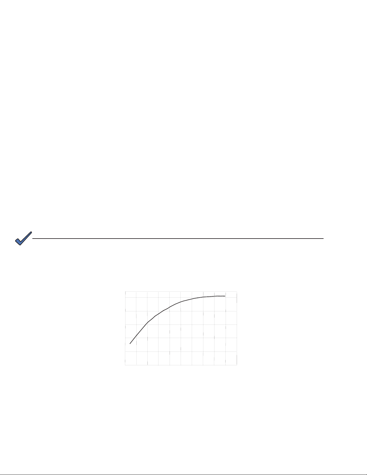
1.4 Capacity
Battery capacity is rated in Ampere hours (Ah) and is the quantity of electricity that can be
supplied during discharge (See Table 1-1).
The actual capacity is related to the utilization ratio of the active positive and negative
materials within the battery. The utilization ratio is inuenced by the depth of discharge, the
structure of the battery, and the manufacturing technology. During normal usage, the factors
that inuence the actual capacity are discharge rate, depth of discharge, end voltage, and
temperature.
The higher the discharge rate, the lower the available capacity.•
As batteries get colder, the available capacity is reduced. This is related to the kinetics of •
the electrochemical reactions and the resistivity of the electrolyte (See Fig. 1-1).
NOTE:
Although the battery can be operated at temperatures below 5ºF (-15ºC), the capacity and ability to
discharge will be dramatically decreased. Similarly, temperatures approaching 122ºF (50ºC) will increase
water loss and corrosion of the plates, resulting in a shorter battery life.
Capacity (%)
Ambient Temperature (ºC)
Fig. 1-1, Available Capacity vs. Ambient Temperature
10
745-680-B11-001, Rev. A
Page 11

1.0 Introduction, continued
1.5 Temperature and Battery Life
High temperatures can harm the battery and reduce its lifespan. Battery life decreases by
50% per 15ºF (~ 9ºC) above the standard operating temperature of 77ºF (25ºC).
To minimize battery damage:
Use temperature compensated chargers.•
Never allow the battery's temperature to exceed +131ºF (+55°C).•
Make sure operating area is properly ventilated, so heat cannot accumulate.•
Provide at least 0.39" (10mm) of space between batteries to enhance convective cooling.•
Visit sites annually to check for shorted cells, improperly set voltages, lter cleaning on •
ventilation systems, etc.
1.6 Internal Resistance and Short-circuit Current
The internal resistance of the battery is affected by temperature and charge state. The
internal resistance is lowest when the battery is fully charged.
Internal
Type
SMU-C6-4.5 22 273
SMU-C6-7 14 429
SMU-C6-12 10 600
SMU-C 12-4.5 35 343
SMU-C 12-7 20 600
SMU-C 12-12 16 750
SMU-C 12-14 16 750
SMU-C 12-18 14 857
SMU-C 12-26 12 1000
SMU-C 12-28 12 1000
SMU-C 12-30 12 1000
SMU-C 12-35 10 1200
SMU-C 12-40 9.5 1263
SMU-C 12-55 6.0 2000
SMU-C 12-65 6.0 2000
SMU-C 12-75 5.5 2182
SMU-C 12-90 5.2 2308
SMU-C 12-100 5.0 2400
SMU-C 12-120 4.5 2667
SMU-C 12-134 4.0 3000
SMU-C 12-150 4.0 3000
SMU-C 12-200 3.8 3158
Resistance
(mΩ)
Short Circuit
Current (A)
Table 1-2, Internal Resistance and Short Circuit Current at 77ºF (25ºC)
CAUTION!
A short circuit current will decrease the voltage of the battery to 0V, and damage the internal
components.
745-680-B11-001, Rev. A
11
Page 12

2.0 Charging Procedures
50%Discharge
100
120
80
20
0.05
60
40
0.25
0.10
0
0.20
0.15
100%Discharge
0
2.33
2.17
2.00
1.83
0
2
4 6
8
10 12
Charge Characteristic
Constant Charge at 25.0A-13.80V (25°C)
Charge Capacity (%)
Charge Current (CA)
Charge Voltage (V/Cell)
Time (Hours)
Charge Voltage
Charge Capacity
Charge Current
NOTE:
Take measurements before and after charging and during discharge to help track changes and problems. Use
a form (see Section 6.0), to record the results. Wait two hours after charging before taking nal measurements
in order to allow the electrolyte to cool sufciently.
CAUTION!
If the heat generated as a result of charging exceeds the rate at which heat can be transferred out
of the battery, thermal runaway can occur and excessive overheating will result.
NOTE:
Refer to your particular charger’s manual for specic instructions regarding charger setup and operation.
2.1 General Charge
The limited current and constant voltage recharge method, also known as the modied
constant potential method, satises the need to have the battery quickly recharged while
ensuring maximum battery life. Figure 2-1 shows the relationship between current, voltage,
and charge for the SMU-C 12-100.
When to Charge
After installing or discharging the battery.•
If the battery has been stored for more than three months and the open circuit voltage is •
lower than 12.6V/block.
12
General Charge Procedure
Charge the batteries with a constant current no greater than 0.2C1.
voltage of 13.8V/block at 77ºF (25ºC) is reached.
Continue charging, reducing the current to maintain a constant voltage of 13.8V/block.2.
Fast Charge Procedure
Charge the batteries with a constant current no greater than 0.2C1.
voltage of 13.8V/block at 77ºF (25ºC) is reached.
Continue charging, reducing the current to maintain a constant voltage of 13.8V/block.2.
The batteries will be fully charged in 18-24 hours when the voltage is a constant 13.8/3.
block and the charge current has not needed adjustment for three continuous hours.
(SMU-C 12-100 with initial 0.1C20A current and limit voltage 13.8V/Cell)
Fig. 2-1, Charge Characteristics Curve
A until an average
20
A until an average
30
745-680-B11-001, Rev. A
Page 13

2.0 Charging Procedures, continued
2.2 Floating Charge
A oat charge keeps the battery in a fully charged state with a small but constant current to
automatically cover capacity loss resultant from self discharge and other discharges.
At 25ºC, the proper oating voltage for the C series is 13.68V/block. The temperature
compensate coefcient is -32.4mV/ºF/block (-18mV/ºC/block).
Ambient Temperature ºF (ºC) Floating Voltage (Vpc)
32 (0) 13.73
41 (5) 13.72
50 (10) 13.71
58 (15) 13.70
68 (20) 13.69
77 (25) 13.68
86 (30) 13.67
95 (35) 13.66
104 (40) 13.65
Table 2-1, Floating Voltage at Different Temperatures
CAUTION!
If the oating voltage is higher than indicated in Table 2-1, then the oating current is also higher
than ideal and will accelerate corruption of the grid and shorten the life of the battery. If the oating
voltage is lower, the battery will not be kept in fully charged state, which will crystallize the PbSO4
(Lead Sulfate), decrease the capacity, and also shorten the life of the battery.
2.3 Discharge
The end voltage is the lowest voltage the battery can be discharged to without causing
damage. Usually, the 20 hour rate (C20) end voltage of a C battery is 10.5V/block. Although
the battery can be discharged below this voltage, doing so will not discharge any more
capacity and can affect its lifespan. It may be impossible to recharge a battery after several
over-discharges. After a discharge, recharge the batteries as soon as possible to maximize
battery life. See Section 5.0 for discharge specications.
Discharge Current (A) Discharge End-Voltage (Vpc)
I < 0.2C 10.5
0.2C ≤ I < 0.5C 10.2
0.5C ≤ I < 1.0C 9.30
I ≥ 1.0C 7.80
745-680-B11-001, Rev. A
Table 2-2, Discharge End-Voltage
13
Page 14

3.0 Storage
32ºF (0ºC)
50ºF (10ºC)
68
ºF
(2
0
º
C
)
8
6ºF (
3
0ºC
)
1
0
4ºF
(
40
º
C)
All lead acid batteries experience self-discharge while in open circuit storage. This causes circuit
voltage and capacity to decrease (see Fig. 3-1).
During storage please note:
The self-discharge rate is related to ambient temperature. The lower the temperature, the less •
the discharge. Batteries should be stored in a clean, ventilated, and dry location with an ambient
temperature of 32ºF to 95ºF (0ºC to 35ºC).
It is important to track open circuit voltage which is related to the density of the electrolyte. If the •
open circuit voltage is lower than 12.6V/block, or the batteries have been stored for three months,
the batteries should be charged to avoid damage caused by self-discharge.
All batteries should be fully charged before storage. Record the storage date and next •
supplemental charge date in a maintenance record (See Fig. 4-2).
Residual Capacity (%)
Storage Time (Months)
Fig. 3-1, Capacity vs. Storage Time
14
745-680-B11-001, Rev. A
Page 15

4.0 Maintenance
4.1 Recommended Maintenance Tasks
In order to prolong battery life, perform regular maintenance and inspections.
Monthly Maintenance
Keep the batteries and battery room clean.•
Measure and record the ambient temperature of the battery room.•
Check for damage and overheating evidence on the terminal, container, and lid.•
Measure and record the total voltage and oating current of the battery system.•
Quarterly Maintenance
Measure and record the oating voltage of every on-line battery. If the voltage of
more than two cells is less than 13.0V after temperature adjustment, discharge the
battery and then recharge at the oat rate. If the problem still exists, conduct yearly
or three-year maintenance procedures. If the problem persists, please contact Alpha
Technologies.
Yearly Maintenance
Check for loose connections.•
Conduct a discharge test to check the exact load, discharging 30-40% of the •
rated capacity.
Three-Year Maintenance
After three years of operation, conduct an 80% capacity test annually.
745-680-B11-001, Rev. A
15
Page 16

4.0 Maintenance, continued
Type: Place:
Test Status: Qty:
Total Voltage (V): Room Temperature:
Current (A):
No. Voltage (V) No. Voltage (V)
1 13
2 14
3 15
4 16
5 17
6 18
7 19
8 20
9 21
10 22
11 23
12 24
Visual check:
Fig. 4-1, VRLA Battery Regular Maintenance Record
16
745-680-B11-001, Rev. A
Page 17

5.0 DischargeSpecications
5.1 Discharge Data with Constant Current
Amperage values for each battery model as a function of time and voltage @ 77°F/25°C.
SMU-C 6-4.5
End voltage 5Min 10Min 15Min 30Min 1h 3h 5h 10h 20h
1.60V 17.6 10.9 8.25 5.03 3.20 1.40 0.86 0.47 0.25
1.67V 16.5 10.4 7.94 4.81 3.16 1.35 0.84 0.46 0.24
1.70V 15.1 10.0 7.75 4.38 3.06 1.26 0.82 0.46 0.24
1.75V 14.8 9.69 7.50 4.16 2.92 1.22 0.80 0.46 0.23
1.80V 13.3 9.25 6.81 3.85 2.73 1.17 0.76 0.45 0.23
1.85V 11.7 8.81 6.13 3.54 2.54 1.13 0.71 0.44 0.22
SMU-C 6-7
End voltage 5Min 10Min 15Min 30Min 1h 3h 5h 10h 20h
1.60V 39.0 24.3 18.3 11.2 5.69 2.50 1.53 0.83 0.45
1.67V 36.6 23.0 17.6 10.7 5.61 2.40 1.49 0.82 0.43
1.70V 33.5 22.2 17.2 9.71 5.44 2.24 1.46 0.82 0.43
1.75V 32.9 21.5 16.6 9.22 5.18 2.17 1.43 0.82 0.42
1.80V 29.4 20.5 15.1 8.54 4.85 2.08 1.34 0.80 0.41
1.85V 26.0 19.6 13.6 7.86 4.52 2.01 1.26 0.79 0.40
SMU-C 6-12
End voltage 5Min 10Min 15Min 30Min 1h 3h 5h 10h 20h
1.60V 65.0 40.4 30.5 18.6 9.38 4.12 2.52 1.37 0.74
1.67V 61.0 38.4 29.3 17.8 9.26 3.96 2.46 1.36 0.71
1.70V 55.9 37.0 28.7 16.2 8.98 3.70 2.41 1.35 0.70
1.75V 54.8 35.8 27.7 15.4 8.55 3.57 2.36 1.35 0.69
1.80V 49.0 34.2 25.2 14.2 8.01 3.43 2.22 1.32 0.67
1.85V 43.3 32.6 22.6 13.1 7.46 3.31 2.08 1.30 0.65
SMU-C 12-4.5
End voltage 5Min 10Min 15Min 30Min 1Hr 3Hr 5Hr 10Hr 20Hr
1.60V 17.6 10.9 8.25 5.03 3.20 1.40 0.86 0.47 0.25
1.67V 16.5 10.4 7.94 4.81 3.16 1.35 0.84 0.46 0.24
1.70V 15.1 10.0 7.75 4.38 3.06 1.26 0.82 0.46 0.24
1.75V 14.8 9.69 7.50 4.16 2.92 1.22 0.80 0.46 0.23
1.80V 13.3 9.25 6.81 3.85 2.73 1.17 0.76 0.45 0.23
1.85V 11.7 8.81 6.13 3.54 2.54 1.13 0.71 0.44 0.22
745-680-B11-001, Rev. A
17
Page 18

5.1 Discharge Data with Constant Current, continued
Amperage values for each battery model as a function of time and voltage @ 77°F/25°C.
SMU-C 12-7
End voltage 5Min 10Min 15Min 30Min 1Hr 3Hr 5Hr 10Hr 20Hr
1.60V 39.0 24.3 18.3 11.2 5.69 2.50 1.53 0.83 0.45
1.67V 36.6 23.0 17.6 10.7 5.61 2.40 1.49 0.82 0.43
1.70V 33.5 22.2 17.2 9.71 5.44 2.24 1.46 0.82 0.43
1.75V 32.9 21.5 16.6 9.22 5.18 2.17 1.43 0.82 0.42
1.80V 29.4 20.5 15.1 8.54 4.85 2.08 1.34 0.80 0.41
1.85V 26.0 19.6 13.6 7.86 4.52 2.01 1.26 0.79 0.40
SMU-C 12-12
End voltage 5Min 10Min 15Min 30Min 1Hr 3Hr 5Hr 10Hr 20Hr
1.60V 65.0 40.4 30.5 18.6 9.38 4.12 2.52 1.37 0.74
1.67V 61.0 38.4 29.3 17.8 9.26 3.96 2.46 1.36 0.71
1.70V 55.9 37.0 28.7 16.2 8.98 3.70 2.41 1.35 0.70
1.75V 54.8 35.8 27.7 15.4 8.55 3.57 2.36 1.35 0.69
1.80V 49.0 34.2 25.2 14.2 8.01 3.43 2.22 1.32 0.67
1.85V 43.3 32.6 22.6 13.1 7.46 3.31 2.08 1.30 0.65
SMU-C 12-14
End voltage 5Min 10Min 15Min 30Min 1Hr 3Hr 5Hr 10Hr 20Hr
1.60V 67.4 41.9 31.6 19.3 9.81 4.31 2.63 1.43 0.77
1.67V 63.2 39.8 30.4 18.4 9.68 4.14 2.58 1.42 0.75
1.70V 57.9 38.3 29.7 16.8 9.38 3.86 2.52 1.41 0.74
1.75V 56.8 37.1 28.7 15.9 8.94 3.74 2.47 1.41 0.72
1.80V 50.8 35.4 26.1 14.8 8.37 3.59 2.32 1.38 0.70
1.85V 44.8 33.8 23.5 13.6 7.80 3.46 2.17 1.36 0.68
SMU-C 12-18
End voltage 5Min 10Min 15Min 30Min 1Hr 3Hr 5Hr 10Hr 20Hr
1.60V 88.6 55.1 41.6 25.4 14.2 6.24 3.81 2.08 1.12
1.67V 83.2 52.3 40.0 24.3 14.0 6.00 3.73 2.06 1.08
1.70V 76.2 50.4 39.1 22.1 13.6 5.60 3.65 2.05 1.07
1.75V 74.7 48.8 37.8 21.0 13.0 5.41 3.57 2.04 1.04
1.80V 66.9 46.6 34.3 19.4 12.1 5.20 3.36 2.00 1.01
1.85V 59.0 44.4 30.9 17.9 11.3 5.01 3.15 1.97 1.00
18
745-680-B11-001, Rev. A
Page 19

5.1 Discharge Data with Constant Current, continued
Amperage values for each battery model as a function of time and voltage @ 77°F/25°C.
SMU-C 12-26
End voltage 5Min 10Min 15Min 30Min 1Hr 3Hr 5Hr 10Hr 20Hr
1.60V 118 73.5 55.5 33.8 19.9 8.74 5.34 2.91 1.57
1.67V 111 69.7 53.4 32.4 19.6 8.40 5.23 2.88 1.52
1.70V 102 67.2 52.1 29.4 19.0 7.84 5.11 2.87 1.49
1.75V 99.6 65.1 50.4 27.9 18.1 7.58 5.00 2.86 1.45
1.80V 89.1 62.2 45.8 25.9 17.0 7.28 4.70 2.80 1.41
1.85V 78.7 59.2 41.2 23.8 15.8 7.02 4.41 2.76 1.38
SMU-C 12-28
End voltage 5Min 10Min 15Min 30Min 1Hr 3Hr 5Hr 10Hr 20Hr
1.60V 118 73.5 55.5 33.8 19.9 8.74 5.34 2.91 1.57
1.67V 111 69.7 53.4 32.4 19.6 8.40 5.23 2.88 1.52
1.70V 102 67.2 52.1 29.4 19.0 7.84 5.11 2.87 1.49
1.75V 99.6 65.1 50.4 27.9 18.1 7.58 5.00 2.86 1.45
1.80V 89.1 62.2 45.8 25.9 17.0 7.28 4.70 2.80 1.41
1.85V 78.7 59.2 41.2 23.8 15.8 7.02 4.41 2.76 1.38
SMU-C 12-30
End voltage 5Min 10Min 15Min 30Min 1Hr 3Hr 5Hr 10Hr 20Hr
1.60V 118 73.5 55.5 33.8 21.3 9.36 5.72 3.12 1.68
1.67V 111 69.7 53.4 32.4 21.0 9.00 5.60 3.09 1.62
1.70V 102 67.2 52.1 29.4 20.4 8.40 5.48 3.07 1.60
1.75V 99.6 65.1 50.4 27.9 19.4 8.12 5.36 3.06 1.56
1.80V 89.1 62.2 45.8 25.9 18.2 7.80 5.04 3.00 1.52
1.85V 78.7 59.2 41.2 23.8 17.0 7.52 4.72 2.96 1.47
SMU-C 12-35
End voltage 5Min 10Min 15Min 30Min 1Hr 3Hr 5Hr 10Hr 20Hr
1.60V 165 103 77.6 47.4 24.9 10.9 6.67 3.63 1.96
1.67V 155 97.6 74.7 45.3 24.5 10.5 6.53 3.60 1.90
1.70V 142 94.1 72.9 41.2 23.8 9.80 6.39 3.59 1.87
1.75V 139 91.2 70.6 39.1 22.7 9.47 6.25 3.57 1.82
1.80V 125 87.1 64.1 36.2 21.2 9.10 5.88 3.50 1.77
1.85V 110 82.9 57.6 33.4 19.8 8.77 5.51 3.45 1.72
745-680-B11-001, Rev. A
19
Page 20

5.1 Discharge Data with Constant Current, continued
Amperage values for each battery model as a function of time and voltage @ 77°F/25°C.
SMU-C 12-40
End voltage 5Min 10Min 15Min 30Min 1Hr 3Hr 5Hr 10Hr 20Hr
1.60V 183 114 86.0 52.4 28.4 12.5 7.63 4.15 2.24
1.67V 172 108 82.7 50.1 28.1 12.0 7.47 4.11 2.17
1.70V 158 104 80.8 45.6 27.2 11.2 7.31 4.10 2.13
1.75V 154 101 78.2 43.3 25.9 10.8 7.15 4.08 2.08
1.80V 138 96.4 71.0 40.1 24.3 10.4 6.72 4.00 2.02
1.85V 122 91.8 63.8 36.9 22.6 10.0 6.29 3.95 1.98
SMU-C 12-55
End voltage 5Min 10Min 15Min 30Min 1Hr 3Hr 5Hr 10Hr 20Hr
1.60V 236 147 111 67.6 39.8 17.5 10.7 5.71 3.09
1.67V 222 139 107 64.7 39.3 16.8 10.5 5.66 2.98
1.70V 203 134 104 58.8 38.1 15.7 10.2 5.63 2.93
1.75V 199 130 101 55.9 36.3 15.2 10.0 5.61 2.85
1.80V 178 124 91.6 51.8 34.0 14.6 9.41 5.50 2.78
1.85V 157 118 82.4 47.6 31.7 14.0 8.80 5.43 2.72
SMU-C 12-65
End voltage 5Min 10Min 15Min 30Min 1Hr 3Hr 5Hr 10Hr 20Hr
1.60V 278 173 130 79.5 46.9 20.6 12.6 6.85 3.70
1.67V 261 164 125 76.0 46.3 19.8 12.3 6.79 3.57
1.70V 239 158 122 69.1 44.9 18.5 12.1 6.76 3.52
1.75V 234 153 118 65.7 42.8 17.9 11.8 6.74 3.43
1.80V 209 146 108 60.8 40.0 17.2 11.1 6.60 3.33
1.85V 185 139 96.8 56.0 37.3 16.5 10.4 6.51 3.26
SMU-C 12-75
End voltage 5Min 10Min 15Min 30Min 1Hr 3Hr 5Hr 10Hr 20Hr
1.60V 319 199 150 91.3 54.0 23.7 14.5 7.89 4.26
1.67V 299 188 144 87.4 53.3 22.8 14.2 7.82 4.12
1.70V 274 182 141 79.4 51.7 21.3 13.9 7.78 4.05
1.75V 269 176 136 75.4 49.2 20.6 13.6 7.76 3.94
1.80V 241 168 124 69.9 46.1 19.8 12.8 7.60 3.84
1.85V 212 160 111 64.3 43.0 19.1 12.0 7.50 3.77
20
745-680-B11-001, Rev. A
Page 21

5.1 Discharge Data with Constant Current, continued
Amperage values for each battery model as a function of time and voltage @ 77°F/25°C.
SMU-C 12-90
End voltage 5Min 10Min 15Min 30Min 1Hr 3Hr 5Hr 10Hr 20Hr
1.60V 366 228 172 105 65.4 28.7 17.5 9.55 5.16
1.67V 344 216 165 100 64.5 27.6 17.2 9.46 4.98
1.70V 315 208 162 91.2 62.6 25.8 16.8 9.42 4.90
1.75V 309 202 156 86.6 59.6 24.9 16.4 9.39 4.78
1.80V 276 193 142 80.2 55.8 23.9 15.5 9.20 4.65
1.85V 244 184 128 73.9 52.0 23.1 14.5 9.07 4.54
SMU-C 12-100
End voltage 5Min 10Min 15Min 30Min 1Hr 3Hr 5Hr 10Hr 20Hr
1.60V 437 272 205 125 72.5 31.8 19.4 10.6 5.72
1.67V 410 258 197 120 71.5 30.6 19.0 10.5 5.52
1.70V 376 249 193 109 69.4 28.6 18.6 10.4 5.44
1.75V 369 241 187 103 66.1 27.6 18.2 10.4 5.29
1.80V 330 230 169 95.8 61.9 26.5 17.1 10.2 5.15
1.85V 291 219 152 88.1 57.7 25.6 16.0 10.1 5.01
SMU-C 12-120
End voltage 5Min 10Min 15Min 30Min 1Hr 3Hr 5Hr 10Hr 20Hr
1.60V 526 327 247 151 86.7 38.1 23.3 12.7 6.85
1.67V 494 310 237 144 85.6 36.6 22.8 12.5 6.61
1.70V 452 299 232 131 83.0 34.2 22.3 12.5 6.50
1.75V 443 290 224 124 79.1 33.0 21.8 12.4 6.33
1.80V 397 277 204 115 74.0 31.7 20.5 12.2 6.16
1.85V 350 264 183 106 69.0 30.6 19.2 12.0 6.03
SMU-C 12-134
End voltage 5Min 10Min 15Min 30Min 1Hr 3Hr 5Hr 10Hr 20Hr
1.60V 469 322 235 141 88.4 36.6 25.6 14.2 7.06
1.67V 422 293 228 137 88.3 36.4 25.4 14.0 7.04
1.70V 401 283 220 134 88.0 36.4 25.4 13.9 7.04
1.75V 356 261 208 131 87.1 36.2 25.2 13.6 7.00
1.80V 322 243 198 127 86.0 36.0 24.9 13.4 6.76
1.85V 244 200 172 117 85.1 35.9 24.7 13.2 6.35
745-680-B11-001, Rev. A
21
Page 22

5.1 Discharge Data with Constant Current, continued
Amperage values for each battery model as a function of time and voltage @ 77°F/25°C.
SMU-C 12-150
End voltage 5Min 10Min 15Min 30Min 1Hr 3Hr 5Hr 10Hr 20Hr
1.60V 656 408 308 188 109 48.0 29.4 16.0 8.64
1.67V 616 387 296 180 108 46.2 28.7 15.8 8.34
1.70V 564 373 289 163 105 43.1 28.1 15.8 8.21
1.75V 553 361 280 155 99.8 41.7 27.5 15.7 7.99
1.80V 495 345 254 144 93.4 40.0 25.9 15.4 7.78
1.85V 437 329 229 132 87.1 38.6 24.2 15.2 7.56
SMU-C 12-200
End voltage 5Min 10Min 15Min 30Min 1Hr 3Hr 5Hr 10Hr 20Hr
1.60V 700 480 350 210 132 54.6 38.2 21.2 10.5
1.67V 630 438 340 204 132 54.4 37.8 20.9 10.5
1.70V 598 422 328 200 131 54.4 37.8 20.7 10.5
1.75V 532 390 310 196 130 54.0 37.5 20.4 10.5
1.80V 480 362 296 190 128 53.8 37.2 20.0 10.1
1.85V 364 298 256 175 127 53.6 36.9 19.7 9.48
22
745-680-B11-001, Rev. A
Page 23

5.2 Discharge Data with Constant Power
Wattage values for each battery model as a function of time and voltage with constant Watts per
cell @ 77°F/25°C.
SMU-C 6-4.5
End voltage 5Min 10Min 15Min 30Min 1Hr 3Hr 5Hr 10Hr 20Hr
1.60V 30.8 19.8 15.1 9.06 5.77 2.49 1.45 0.94 0.50
1.67V 29.8 19.3 14.9 8.88 5.74 2.41 1.44 0.93 0.49
1.70V 28.0 19.1 14.8 8.31 5.63 2.30 1.43 0.93 0.48
1.75V 28.2 19.0 14.6 8.06 5.53 2.25 1.41 0.92 0.47
1.80V 25.8 18.7 13.6 7.69 5.21 2.18 1.37 0.90 0.46
1.85V 23.4 17.8 12.3 7.20 4.90 2.12 1.33 0.88 0.44
SMU-C 6-7
End voltage 5Min 10Min 15Min 30Min 1Hr 3Hr 5Hr 10Hr 20Hr
1.60V 68.4 43.8 33.4 20.1 10.3 4.43 2.58 1.71 0.90
1.67V 66.0 42.7 33.0 19.7 10.2 4.29 2.57 1.70 0.86
1.70V 62.6 42.3 32.7 18.4 10.0 4.10 2.53 1.69 0.85
1.75V 62.2 42.2 32.4 17.9 9.83 4.00 2.51 1.66 0.83
1.80V 57.2 41.5 30.1 17.1 9.27 3.88 2.43 1.62 0.81
1.85V 51.9 39.4 27.3 16.0 8.71 3.77 2.36 1.58 0.79
SMU-C 6-12
End voltage 5Min 10Min 15Min 30Min 1Hr 3Hr 5Hr 10Hr 20Hr
1.60V 114 73.0 55.7 33.5 16.9 7.30 4.25 2.82 1.48
1.67V 110 71.2 55.0 32.8 16.8 7.08 4.24 2.80 1.43
1.70V 104 70.5 54.5 30.7 16.5 6.76 4.18 2.78 1.41
1.75V 104 70.3 54.1 29.8 16.2 6.60 4.14 2.73 1.37
1.80V 95.4 69.2 50.1 28.4 15.3 6.41 4.02 2.67 1.34
1.85V 86.5 65.7 45.5 26.6 14.4 6.21 3.89 2.60 1.31
SMU-C 12-4.5
End voltage 5Min 10Min 15Min 30Min 1Hr 3Hr 5Hr 10Hr 20Hr
1.60V 30.8 19.8 15.1 9.06 5.77 2.49 1.45 0.94 0.50
1.67V 29.8 19.3 14.9 8.88 5.74 2.41 1.44 0.93 0.49
1.70V 28.2 19.1 14.8 8.31 5.63 2.30 1.43 0.93 0.48
1.75V 28.0 19.0 14.6 8.06 5.53 2.25 1.41 0.92 0.47
1.80V 25.8 18.7 13.6 7.69 5.21 2.18 1.37 0.90 0.46
1.85V 23.4 17.8 12.3 7.20 4.90 2.12 1.33 0.88 0.44
745-680-B11-001, Rev. A
23
Page 24

5.2 Discharge Data with Constant Power, continued
Wattage values for each battery model as a function of time and voltage with constant Watts per
cell @ 77°F/25°C
SMU-C 12-7
End voltage 5Min 10Min 15Min 30Min 1Hr 3Hr 5Hr 10Hr 20Hr
1.60V 68.4 43.8 33.4 20.1 10.3 4.43 2.58 1.71 0.90
1.67V 66.0 42.7 33.0 19.7 10.2 4.29 2.57 1.70 0.86
1.70V 62.6 42.3 32.7 18.4 10.0 4.10 2.53 1.69 0.85
1.75V 62.2 42.2 32.4 17.9 9.83 4.00 2.51 1.66 0.84
1.80V 57.2 41.5 30.1 17.1 9.27 3.88 2.43 1.64 0.83
1.85V 51.9 39.4 27.3 16.0 8.71 3.77 2.36 1.58 0.80
SMU-C 12-12
End voltage 5Min 10Min 15Min 30Min 1Hr 3Hr 5Hr 10Hr 20Hr
1.60V 114 73.0 55.7 33.5 16.9 7.30 4.25 2.82 1.48
1.67V 110 71.2 55.0 32.8 16.8 7.08 4.24 2.80 1.43
1.70V 104 70.5 54.5 30.7 16.5 6.76 4.18 2.78 1.41
1.75V 104 70.3 54.1 29.8 16.2 6.60 4.14 2.74 1.37
1.80V 95.4 69.2 50.1 28.4 15.3 6.41 4.02 2.71 1.34
1.85V 86.5 65.7 45.5 26.6 14.4 6.21 3.89 2.62 1.32
SMU-C 12-14
End voltage 5Min 10Min 15Min 30Min 1Hr 3Hr 5Hr 10Hr 20Hr
1.60V 118 75.7 57.7 34.7 17.7 7.64 4.45 2.94 1.55
1.67V 114 73.8 57.0 34.0 17.6 7.40 4.43 2.93 1.49
1.70V 108 73.0 56.5 31.9 17.3 7.07 4.37 2.91 1.47
1.75V 107 72.8 56.0 30.9 17.0 6.90 4.33 2.87 1.44
1.80V 98.9 71.7 52.0 29.5 16.0 6.70 4.20 2.83 1.40
1.85V 89.7 68.1 47.1 27.6 15.0 6.50 4.06 2.80 1.34
SMU-C 12-18
End voltage 5Min 10Min 15Min 30Min 1Hr 3Hr 5Hr 10Hr 20Hr
1.60V 155 99.6 75.9 45.7 25.7 11.1 6.44 4.27 2.24
1.67V 150 97.1 75.0 44.7 25.5 10.7 6.42 4.24 2.16
1.70V 142 96.1 74.4 41.9 25.0 10.2 6.33 4.24 2.16
1.75V 141 95.8 73.7 40.7 24.6 10.0 6.28 4.16 2.08
1.80V 130 94.4 68.4 38.8 23.2 9.71 6.08 4.11 2.03
1.85V 118 89.5 62.0 36.3 21.8 9.41 5.89 3.97 2.00
24
745-680-B11-001, Rev. A
Page 25

5.2 Discharge Data with Constant Power, continued
Wattage values for each battery model as a function of time and voltage with constant Watts per
cell @ 77°F/25°C
SMU-C 12-26
End voltage 5Min 10Min 15Min 30Min 1Hr 3Hr 5Hr 10Hr 20Hr
1.60V 207 133 101 60.9 35.9 15.5 9.02 5.97 3.14
1.67V 200 129 100 59.7 35.7 15.0 8.98 5.94 3.02
1.70V 190 128 99.2 55.9 35.0 14.3 8.87 5.90 2.99
1.75V 188 128 98.3 54.2 34.4 14.0 8.79 5.74 2.91
1.80V 173 126 91.2 51.7 32.4 13.6 8.52 5.62 2.82
1.85V 157 119 82.7 48.4 30.5 13.2 8.24 5.54 2.73
SMU-C 12-28
End voltage 5Min 10Min 15Min 30Min 1Hr 3Hr 5Hr 10Hr 20Hr
1.60V 207 133 101 60.9 35.9 15.5 9.02 5.97 3.14
1.67V 200 129 100 59.7 35.7 15.0 8.98 5.94 3.02
1.70V 190 128 99.2 55.9 35.0 14.3 8.87 5.90 2.99
1.75V 188 128 98.3 54.2 34.4 14.0 8.79 5.74 2.91
1.80V 173 126 91.2 51.7 32.4 13.6 8.52 5.62 2.82
1.85V 157 119 82.7 48.4 30.5 13.2 8.24 5.54 2.73
SMU-C 12-30
End voltage 5Min 10Min 15Min 30Min 1Hr 3Hr 5Hr 10Hr 20Hr
1.60V 207 133 101 60.9 38.5 16.6 9.67 6.40 3.36
1.67V 200 129 100 59.7 38.2 16.1 9.63 6.36 3.24
1.70V 190 128 99.2 55.9 37.5 15.4 9.50 6.32 3.20
1.75V 188 128 98.3 54.2 36.9 15.0 9.42 6.24 3.12
1.80V 173 126 91.2 51.7 34.8 14.6 9.13 6.16 3.04
1.85V 157 119 82.7 48.4 32.7 14.1 8.83 6.08 2.92
SMU-C 12-35
End voltage 5Min 10Min 15Min 30Min 1Hr 3Hr 5Hr 10Hr 20Hr
1.60V 290 186 142 85.3 44.9 19.4 11.3 7.47 3.92
1.67V 280 181 140 83.5 44.6 18.8 11.2 7.42 3.78
1.70V 265 179 139 78.2 43.8 17.9 11.1 7.37 3.73
1.75V 264 179 138 75.9 43.0 17.5 11.0 7.28 3.64
1.80V 243 176 128 72.4 40.6 17.0 10.6 7.19 3.55
1.85V 220 167 116 67.8 38.1 16.5 10.3 7.09 3.41
745-680-B11-001, Rev. A
25
Page 26

5.2 Discharge Data with Constant Power, continued
Wattage values for each battery model as a function of time and voltage with constant Watts per
cell @ 77°F/25°C
SMU-C 12-40
End voltage 5Min 10Min 15Min 30Min 1Hr 3Hr 5Hr 10Hr 20Hr
1.60V 321 206 157 94.4 51.3 22.1 12.9 8.53 4.48
1.67V 310 201 155 92.5 51.0 21.4 12.8 8.48 4.32
1.70V 294 199 154 86.6 50.0 20.5 12.7 8.43 4.27
1.75V 292 198 152 84.0 49.2 20.0 12.6 8.32 4.16
1.80V 269 195 141 80.1 46.3 19.4 12.2 8.07 4.05
1.85V 244 185 128 75.0 43.6 18.8 11.8 7.98 4.00
SMU-C 12-55
End voltage 5Min 10Min 15Min 30Min 1Hr 3Hr 5Hr 10Hr 20Hr
1.60V 415 266 203 122 71.8 31.0 18.0 11.7 6.00
1.67V 400 259 200 119 71.4 30.0 18.0 11.6 5.91
1.70V 379 256 198 112 70.0 28.7 17.7 11.5 5.82
1.75V 377 255 197 108 68.8 28.0 17.6 11.3 5.70
1.80V 347 252 182 103 64.9 27.2 17.0 11.2 5.62
1.85V 315 239 165 96.8 61.0 26.4 16.5 11.0 5.53
SMU-C 12-65
End voltage 5Min 10Min 15Min 30Min 1Hr 3Hr 5Hr 10Hr 20Hr
1.60V 487 312 238 143 84.7 36.5 21.3 13.9 7.28
1.67V 470 304 235 140 84.1 35.4 21.2 13.8 7.02
1.70V 446 301 233 131 82.5 33.8 20.9 13.7 6.93
1.75V 443 300 231 127 81.1 33.0 20.7 13.5 6.76
1.80V 408 296 214 121 76.5 32.0 20.1 13.3 6.67
1.85V 370 281 194 114 71.9 31.1 19.4 13.2 6.62
SMU-C 12-75
End voltage 5Min 10Min 15Min 30Min 1Hr 3Hr 5Hr 10Hr 20Hr
1.60V 560 358 273 164 97.5 42.1 24.5 16.0 8.40
1.67V 540 349 270 161 96.9 40.7 24.4 15.9 8.10
1.70V 512 346 268 151 95.1 38.9 24.1 15.8 8.00
1.75V 502 345 265 146 93.4 38.0 23.9 15.6 7.90
1.80V 468 340 246 140 88.1 36.9 23.1 15.4 7.72
1.85V 425 322 223 131 82.8 35.8 22.4 15.2 7.62
26
745-680-B11-001, Rev. A
Page 27

5.2 Discharge Data with Constant Power, continued
Wattage values for each battery model as a function of time and voltage with constant Watts per
cell @ 77°F/25°C
SMU-C 12-90
End voltage 5Min 10Min 15Min 30Min 1Hr 3Hr 5Hr 10Hr 20Hr
1.60V 643 412 314 189 118 50.9 29.6 19.6 10.3
1.67V 620 401 310 185 117 49.3 29.5 19.5 9.94
1.70V 588 397 307 173 115 47.1 29.1 19.4 9.81
1.75V 584 396 305 168 113 46.0 28.9 19.1 9.57
1.80V 538 390 283 160 107 44.7 28.0 18.9 9.49
1.85V 488 370 256 150 100 43.3 27.1 18.6 9.32
SMU-C 12-100
End voltage 5Min 10Min 15Min 30Min 1Hr 3Hr 5Hr 10Hr 20Hr
1.60V 767 491 375 225 131 56.4 32.9 21.8 11.4
1.67V 740 479 370 221 130 54.7 32.7 21.6 11.0
1.70V 701 474 367 207 128 52.2 32.3 21.5 10.9
1.75V 697 473 364 201 125 51.0 32.0 21.2 10.6
1.80V 642 466 337 191 118 49.5 31.0 20.9 10.5
1.85V 582 442 306 179 111 48.0 30.0 20.5 10.3
SMU-C 12-120
End voltage 5Min 10Min 15Min 30Min 1Hr 3Hr 5Hr 10Hr 20Hr
1.60V 923 591 451 271 156 67.5 39.3 26.0 13.7
1.67V 890 576 445 266 156 65.4 39.1 25.9 13.2
1.70V 844 570 441 249 153 62.5 38.6 25.4 13.0
1.75V 838 568 438 241 150 61.0 38.3 25.1 12.7
1.80V 772 560 406 230 141 59.2 37.1 24.7 12.4
1.85V 700 531 368 215 133 57.4 35.9 24.3 12.2
SMU-C 12-134
End voltage 5Min 10Min 15Min 30Min 1Hr 3Hr 5Hr 10Hr 20Hr
1.60V 773 533 415 265 174 70.2 48.9 28.4 14.1
1.67V 733 527 411 260 168 70.2 48.9 28.0 14.1
1.70V 685 513 405 253 164 70.2 48.9 27.8 14.1
1.75V 638 480 381 247 163 69.1 48.4 27.3 14.0
1.80V 572 446 358 240 160 68.2 47.6 26.8 13.5
1.85V 458 370 312 220 158 67.9 46.9 26.3 12.7
745-680-B11-001, Rev. A
27
Page 28

5.2 Discharge Data with Constant Power, continued
Wattage values for each battery model as a function of time and voltage with constant Watts per
cell @ 77°F/25°C
SMU-C 12-150
End voltage 5Min 10Min 15Min 30Min 1Hr 3Hr 5Hr 10Hr 20Hr
1.60V 1151 737 562 338 198 85.2 49.6 32.9 17.2
1.67V 1110 718 555 331 196 82.5 49.4 32.6 16.6
1.70V 1052 711 550 310 193 78.8 48.8 31.6 16.4
1.75V 1045 709 546 301 189 77.0 48.3 31.4 16.0
1.80V 963 698 506 287 178 74.7 46.8 30.8 15.6
1.85V 873 663 459 269 168 72.5 45.3 30.4 15.3
SMU-C 12-200
End voltage 5Min 10Min 15Min 30Min 1Hr 3Hr 5Hr 10Hr 20Hr
1.60V 1154 796 620 396 260 105 73.0 42.4 21.1
1.67V 1094 786 614 388 251 105 73.0 41.8 21.0
1.70V 1022 766 604 378 245 105 73.0 41.5 21.0
1.75V 952 716 568 368 243 103 72.2 40.7 20.9
1.80V 854 666 534 358 238 102 71.0 40.0 20.2
1.85V 684 552 466 328 236 101 70.0 39.3 19.0
28
745-680-B11-001, Rev. A
Page 29

6.0 Forms
6.1 Discharge Recording Form
Model of Battery Date
Battery Bank No. Room Temperature
Charging Current Total battery Voltage
Remarks
Cell # Inital Voltage
Cell Voltage at Time Period End
15min 30min 1hr 2hr 3hr 4hr 4:30hr 5 hr
745-680-B11-001, Rev. A
29
Page 30

this page intentionally blank
Page 31

Page 32

Alpha Technologies Inc.
3767 Alpha Way
Bellingham, WA 98226
United States
Tel: +1 360 647 2360
Fax: +1 360 671 4936
Alpha Technologies Ltd.
7700 Riverfront Gate
Burnaby, BC V5J 5M4
Canada
Tel: +1 604 436 5900
Fax: +1 604 436 1233
Toll Free: +1 800 667 8743
Alpha Industrial Power Inc.
1075 Satellite Blvd NW,
Suite 400
Suwanee, GA 30024
United States
Tel: +1 678 475 3995
Fax: +1 678 584 9259
Alpha Energy
1628 W Williams Drive
Phoenix, AZ 85027
United States
Tel: +1 602 997 1007
Fax: +1 623 249 7833
Alpha Technologies Europe Ltd.
Twyford House Thorley
Bishop’s Stortford
Hertfordshire, CM22 7PA
United Kingdom
Tel: +44 1279 501110
Fax: +44 1279 659870
Alpha Technologies
Suite 1903, 19/F., Tower 1
33 Canton Road, Tsim Sha Tsui
China Hong Kong City, Kowloon
Hong Kong
Phone: +852 2736 8663
Fax: +852 2199 7988
Alpha Technologies GmbH
Hansastrasse 8
D-91126
Schwabach, Germany
Tel: +49 9122 79889 0
Fax: +49 9122 79889 21
Alphatec Ltd.
339 St. Andrews St.
Suite 101 Andrea Chambers
P.O. Box 56468
3307 Limassol, Cyprus
Tel: +357 25 375 675
Fax: +357 25 359 595
Alpha Innovations Brasil
Avenida Ibirapuera,
2120 – Cj 76
Moema - 04028-001
Santos SP, Brazil
Tel: +55 11 2476 0150
Fax: +55 11 2476 0150
Technologies Argus
First de Mexico
Anatole France Num. 17
Colonia Polanco
11560, México D.F.
Tel: +52 55 5280 6990
Alpha TEK ooo
Khokhlovskiy Pereulok 16
Stroenie 1, Ofce 403
Moscow, 109028
Russia
Tel: +7 495 916 1854
Fax: +7 495 916 1349
Alphatec Baltic
S. Konarskio Street 49-201
Vilnius, LT-03123
Lithuania
Tel: +370 5 210 5291
Fax: +370 5 210 5292
Visit us at www.alpha.com
Due to continuing product development, Alpha Technologies reserves the right to change specications without notice.
Copyright © 2010 Alpha Technologies. All Rights Reserved. Alpha® is a registered trademark of Alpha Technologies. 745-680-B11-001 Rev. A (12/2010)
 Loading...