

Page 1
TM
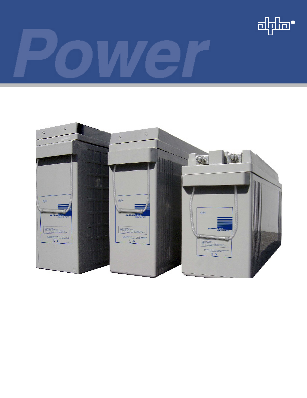
AlphaCell
Valve Regulated Lead Acid Battery
SMU-F
Technical Manual
AlphaCell SMU-F Valve Regulated Lead Acid Battery
Effective: February 2007
Alpha Technologies
Page 2

Page 3
AlphaCell SMU-F
Valve Regulated Lead Acid Battery
SMU-F-BATTERY
Effective Date: February 2007
Copyright© 2007
Alpha Technologies, Inc.
member of The Group
NOTE:
Photographs contained in this manual are for illustrative purposes only. These photographs may not match
your installation.
NOTE:
Operator is cautioned to review the drawings and illustrations contained in this manual before proceeding. If
there are questions regarding the safe operation of this product, please contact Alpha Technologies or your
nearest Alpha representative.
NOTE:
Alpha shall not be held liable for any damage or injury involving its enclosures, power supplies, generators,
batteries, or other hardware if used or operated in any manner or subject to any condition not consistent with
its intended purpose, or is installed or operated in an unapproved manner, or improperly maintained.
TM
Contacting Alpha Technologies: www.alpha.com
or
For general product information and customer service (7 AM to 5 PM, Pacic Time), call
1-800-863-3930,
For complete technical support, call
1-800-863-3364
7 AM to 5 PM, Pacic Time or 24/7 emergency support
3
Page 4

Table of Contents
Safety Notes .......................................................................................................................... 6
Battery Safety Notes.............................................................................................................. 7
Chemical Hazards ................................................................................................................. 7
Recycling and Disposal Instructions ...................................................................................... 7
1.0 Introduction ................................................................................................................. 8
1.1 Main Applications ............................................................................................. 8
1.2 Specications and General Information ........................................................... 9
2.0 Charging ....................................................................................................................11
2.1 Float Charge ...................................................................................................11
2.2 Recharge Following Discharge ...................................................................... 12
3.0 Storage ..................................................................................................................... 13
4.0 Discharge Specications .......................................................................................... 14
5.0 Forms ........................................................................................................................ 17
4
SMU-F-BATTERY
Page 5

Tables and Figures
Table 1-1, Mechanical Specications .................................................................................... 9
Fig. 1-1, Dimensions.............................................................................................................. 9
Fig. 1-2, Capacity Related toTemperature and Discharge Rate .......................................... 10
Table 2-1, Float Voltages ......................................................................................................11
Fig. 2-1, Recharge Time and Capacity Restored as a Function of Current Limit ................ 13
Table 3-1, Boost Charge Intervals ....................................................................................... 13
Table 4-1, Discharge Data (A, 70–77ºF (21–25ºC)) ............................................................ 14
Table 4-2, Discharge Data (A, 70–77ºF (21–25ºC)) ............................................................ 15
Table 4-3, Discharge Data (A, 70–77ºF (21–25ºC)) ............................................................ 16
Fig. 5-1, Charge Recording Form ........................................................................................ 17
Fig. 5-2, Discharge Recording Form ................................................................................... 20
SMU-F-BATTERY
5
Page 6
Safety Notes
Review the drawings and illustrations contained in this manual before proceeding. If there are any questions
regarding the safe installation or operation of the system, contact Alpha Technologies or the nearest Alpha
representative. Save this document for future reference.
To reduce the risk of injury or death, and to ensure the continued safe operation of this product, the following
symbols have been placed throughout this manual. Where these symbols appear, use extra care and
attention.
ATTENTION:
The use of ATTENTION is only for specic regulatory/code requirements that may affect the placement of
equipment and installation procedures.
NOTE:
A NOTE gives readers additional information to help them complete a specic task or procedure.
CAUTION!
The use of CAUTION indicates safety information intended to PREVENT DAMAGE to material or
equipment.
WARNING!
A WARNING presents safety information to PREVENT INJURY OR DEATH to the
technician or user.
6
SMU-F-BATTERY
Page 7

Battery Safety Notes
WARNING!
Lead-acid batteries contain dangerous voltages, currents and corrosive material. Battery
installation, maintenance, service and replacement must be performed only by authorized
personnel.
Chemical Hazards
Any gelled or liquid leakage from a valve-regulated lead-acid (VRLA) battery contains dilute sulfuric acid,
which is harmful to the skin and eyes. Emissions are electrolytic, and are electrically conductive and
corrosive.
To avoid injury:
Servicing and connection of batteries shall be performed by, or under the direct supervision of, personnel
•
knowledgeable of batteries and the required safety precautions.
Always wear eye protection, rubber gloves, and a protective vest when working near batteries. Remove all metallic
•
objects from hands and neck.
Batteries produce explosive gases. Keep all open ames and sparks away from batteries.
•
Use tools with insulated handles, do not rest any tools on top of batteries.
•
Lead-acid batteries contain or emit chemicals known to the State of California to cause cancer and birth defects or
•
other reproductive harm. Battery post terminals and related accessories contain lead and lead compounds. Wash
hands after handling (California Proposition 65).
Wear protective clothing (insulated gloves, eye protection, etc.) when installing, maintaining, servicing, or replacing
•
batteries.
If any battery emission contacts the skin, wash immediately and thoroughly with water. Follow your company’s
•
approved chemical exposure procedures.
Neutralize any spilled battery emission with the special solution contained in an approved spill kit or with a solution
•
of one pound bicarbonate of soda to one gallon of water. Report a chemical spill using your company’s spill reporting
structure and seek medical attention if necessary.
Always replace batteries with those of an identical type and rating. Never install old or untested batteries.
•
Do not charge batteries in a sealed container. Each individual battery should have at least 0.5 inches of space
•
between it and all surrounding surfaces to allow for convection cooling.
All battery compartments must have adequate ventilation to prevent accumulation of potentially dangerous gas.
•
Ventilation should prevent trapped hydrogen gas pockets from exceeding a 1% concentration as per regulation 70E
of the National Fire Protection Agency (NFPA).
Prior to handling the batteries, touch a grounded metal object to dissipate any static charge that may have developed
•
on your body.
Never use uninsulated tools or other conductive materials when installing, maintaining, servicing, or replacing
•
batteries.
Use special caution when connecting or adjusting battery cabling. An improperly connected or an unconnected
•
battery cable can make contact with an unintended surface that can result in arcing, re, or possible explosion.
A battery showing signs of cracking, leaking, or swelling should be replaced immediately by authorized personnel
•
using a battery of identical type and rating.
Equipment Cautions
Do not operate NiCd and lead-acid batteries in the same room. NiCd emissions will neutralize the lead-acid solution,
•
rendering the battery useless.
Overcharging the battery can result in a loss of capacity and excess release of gas.
•
Recycling and Disposal Instructions
Spent or damaged batteries are considered environmentally unsafe. Always recycle used batteries or dispose of the
batteries in accordance with all federal, state and local regulations.
SMU-F-BATTERY
7
Page 8

1.0 Introduction
The SMU-F range of Valve Regulated Lead Acid (VRLA) batteries is designed to meet the needs of
the wireless communications industry. Safety, reliability and a long service life in standby applications
are the result of an industry-leading manufacturing technology and a product design purpose-built for
the requirements of a wireless communications network.
Alpha Technologies also offers a full line of racking solutions to accomodate the SMU-F range of
batteries. Front-terminal SMU-F batteries provide easy access to terminals for installation and
maintenance, eliminating the need to purchase expensive sliding mechanisms to provide terminal
access.
The SMU-F range includes 8 models – a revolutionary idea to reduce space requirements and
minimize the number of terminations – to make it easier to install and maintain these batteries. Other
features of the SMU-F range include:
No additional water is needed throughout their life thus reducing maintenance costs as compared
•
to vented (ooded) batteries.
Meets the requirements of modern electronic equipment and is compatible with normally available
•
recharging systems.
Compact construction and excellent performance at high rates of discharge provides big savings
•
in volume and weight as compared to conventional ooded, vented batteries.
Because there are no perceptible amounts of gas emissions under normal operating conditions,
•
batteries can be installed in the same environment where people live and work.
Substantial savings in installation and maintenance costs compared to conventional vented
•
batteries.
No special rooms are required and only minimal maintenance is needed during the life of the
•
battery.
Smaller, lighter, and more compact than traditional batteries, SMU-F batteries, with integrated
•
handles, are easy to move.
Delivered lled and charged for immediate use.
•
1.1 Main Applications
Wireless Communications
SPACELL SMU-F batteries have a proven track record of performance in many parts of
the communications network including Central Ofce, Huts, CEV’s and Remote Terminal
cabinets.
Uninterruptible Power Supplies (UPS)
The low internal resistance Absorbent Glass Mat (AGM) FA batteries make them a good
choice for U.P.S. applications, especially for Industrial U.P.S. and extended run-time
applications.
8
SMU-F-BATTERY
Page 9

1.0 Introduction, continued
1.2 Specications and General Information
Specications are subject to change without notice.
Type Length
SMU-F 12-50-FR 15.4/390 4.1/105 8.9/227 47.4/21.5 8mm
SMU-F 12-75-FR 21.9/558 4.1/105 8.9/227 68.3/31.0 8mm
SMU-F 12-85-FR 15.6/395 4.1/105 10.6/270 69.5/31.5 8mm
SMU-F 12-105-FR 20.1/511 4.3/110 9.4/238 79.4/36.0 8mm
SMU-F 12-125-FR 21.9/558 4.9/125 10.6/270 108.0/49.0 8mm
SMU-F 12-155-FR 21.9/558 4.9/124 11.1/283 119.0/54.0 8mm
SMU-F 12-170-FR 21.9/558 4.9/124 12.2/310 129.8/59.0 8mm
(in/mm)
Width
(in/mm)
Height
(in/mm)
Weight
(lb/kg)
Standard Stud Size *
*a 6mm stud size can be ordered as an option
Table 1-1, Mechanical Specications
Fig. 1-1, Dimensions
Torque specications
Torque specications are 8.4Nm (75lbf-in). Torque all terminal connections to the specied
value. Improper torquing can result in loose connections or damaged terminals.
Electrolyte
The electrolyte is sulfuric acid with a specic gravity of 1.320 at 77ºF (25ºC) and has the same
purity characteristics as other types of high quality lead acid batteries.
Short circuit
SMU-F batteries are designed to withstand a short circuit current for 1 minute without damage.
Cycling
The SMU-F range of batteries will deliver 200 cycles (at C8 to 1.75Vpc and 77ºF (25ºC)).
Life
The end of service life of a battery is dened as the point at which the battery’s actual capacity
has reached 80% of its nominal capacity. The design life of the FA family of batteries is 15 years
of oat life. However, since users cannot often duplicate laboratory conditions, such as controlling
temperature, voltage, and AC ripple, this period may vary. Battery life will decrease by roughly
half for every 14.4–18ºF (8–10°C) above or below nominal operating temperature (68ºF (20°C)).
Low Voltage Interruption
Because the DC load will shut off if the voltage gets too low, damaging equipment, Alpha
Technologies recommends the use of Low Voltage Disconnects (LVDs) to maximize battery life.
LVDs protect sensitive equipment from low voltages, and prevent the battery from being overdischarged. LVDs can be placed on either the load or battery side.
A string of batteries is a series of individual 2V cells working together. After discharge, the
voltages of individual cells vary based on the exact capacity of each cell. Most users try to
terminate the load when the batteries reach 1.75Vpc to ensure no individual cells fall below
0 VDC. Cells that fall below 0 VDC are said to be reversed. Alpha Technologies strongly
recommends that cells which have been reversed be replaced immediately.
SMU-F-BATTERY
9
Page 10

1.2 Specications and General Information, continued
Gassing
SMU-F batteries have a high recombination efciency (>98%) and for cells operated at 68ºF
(20ºC) under normal operating conditions venting is virtually negligible. The following gassing
rates can be expected:
2 ml/Ah/cell/month at a oat voltage of 2.27Vpc.
•
10 ml/Ah/cell/month at a recharge voltage of 2.40Vpc.
•
As hydrogen should never exceed 2% by volume in any enclosed space, all rooms or
cabinets where batteries are installed should have natural ventilation and not be fully sealed.
Customers should also be aware that hydrogen is very light and can “pocket” in portions of
the room or cabinet. Designers should take this into account when designing the battery
operating space.
Each cell has a one-way valve to permit the release of gases from the cell whenever the
internal pressure exceeds the xed safety value. The valve is rated at approximately 0.1
atmospheres (1.5 PSIG or 10 kPa).
Operation of batteries in parallel
When the required capacity is greater than the maximum available from our range, it is
possible to connect batteries in parallel to obtain the desired capacity.
Use only blocks of the same model
•
Make all electrical connections of parallel circuits between the batteries as equal and
•
symmetrical as possible (e.g., length and type of connector) to minimize possible
impedance variations
Capacity
The battery capacity is rated in ampere hours (Ah) and indicates the quantity of electricity
which can be supplied during discharge. The capacity depends on the quantity of the active
materials contained in the battery (thus on dimensions and weight) as well as the discharge
rate and temperature. The higher the discharge rate, the lower the available capacity. As
batteries get colder, the available capacity is reduced. This is related to the kinetics of the
electrochemical reactions and the resistivity of the electrolyte (see Fig. 1-2).
110%
100%
90%
80%
70%
60%
Available Capacity
50%
1 -10 hour discharge
5 -59 minute discharge
10
40%
30%
20%
-4 (-20) 14 (-10) 32 (0) 50 (10)
68 (20) 86 (30) 104 (40)
Temperature ºF (ºC)
Fig. 1-2, Capacity Related toTemperature and Discharge Rate
122 (50) 140 (60)
SMU-F-BATTERY
Page 11

2.0 Charging
NOTE:
Refer to your particular charger’s manual for specic instructions regarding charger setup and operation.
During operation, verify batteries are:
Float-charged in order to maintain a fully charged condition during the standby period.
•
Completely recharged after a discharge. Recharge as soon as possible to ensure maximum
•
protection against subsequent power outages. Early recharge also ensures maximum battery life.
While recharging procedures vary depending on the recharge time and battery life, generally charging
is performed as follows:
At a voltage equal to the oat voltage and a low current (long recharge time);
•
At a voltage not higher than 2.4Vpc and a high current (faster recharge).
•
The IU recharge method, also known as modied constant potential, has been used for many years
and in a variety of applications. It satises the need to have the battery quickly recharged while
ensuring maximum battery life.
Recharge at a constant current rate until the voltage reaches a pre-set value.
1.
Maintain the pre-set voltage and decrease the current until a minimum dened value is reached.
2.
Complete the recharge at a nal constant voltage value equal to or less than that dened for oat
3.
charge and decrease the current to the value used in oat.
2.1 Float Charge
2.27V at 68ºF (20ºC) is the recommended voltage for oat charge. This voltage ensures the
maximum life of SMU-F batteries. These batteries can operate over a temperature range
of -4ºF (-20ºC) to +140ºF (+60ºC). Performance and life are greatly reduced outside of this
temperature range.
Temperature ºF (ºC) Recommended Float (Vpc)
The equation to determine oat voltage at a given temperature is:
V = 2.32 – 0.0025 * T
V = Float Voltage
T = Temperature
or
-2.5 mV per 1.8ºF (1ºC) temperature uctuation outside of 68ºF (20ºC)
The minimum and maximum recommended voltages are 0.010V on either side of the
determined voltage at a given temperature. Batteries oated at voltages above the range will
have an increased risk of dry out, grid corrosion and thermal runaway. Batteries oated below
the range will not receive enough charge, and will be subject to sulfation.
-4 (-20) 2.37
32 (0) 2.32
68 (20) 2.27
77 (25) 2.26
140 (60) 2.17
Table 2-1, Float Voltages
SMU-F-BATTERY
11
Page 12

2.1 Float Charge, continued
Float Current
The normal oat current observed in fully charged SMU-F batteries at 2.27Vpc at a
temperature of 68ºF (20ºC) is approximately 30mA per 100Ah. Because of the nature of
recombination phenomena, the oat current observed in SMU-F batteries is normally higher
than that of vented batteries and is not an indication of the state of charge of the batteries.
Thermal Runaway
Float current is primarily a function of voltage and temperature. As either voltage or
temperature increases, the oat current also increases exponentially. Much of the oat
current is going into the recombination reaction, which is exothermic. If the heat generated by
recombination exceeds the rate at which heat can be transferred out of the battery (based on
conduction, convection, and black body radiation), thermal runaway can occur. The battery
will continue to take very large amounts of current from the rectier and excessive gassing
and overheating will result.
WARNING!
In the most severe cases of thermal runaway, equipment can be damaged by sulfuric acid mist that escapes
the battery, hydrogen can build up to dangerous levels, and battery cases can rupture because of weakening
and melting of the plastic. Ruptured cases can lead to ground faults.
To minimize the risk of thermal runaway:
Use temperature compensated chargers
1.
Never allow the batteries to exceed 131ºF (55ºC)
2.
Make sure cabinets are properly ventilated
3.
Provide spacing between batteries to enhance convective cooling
4.
Visit sites annually to check for shorted cells, improperly set voltages, lter cleaning on
5.
ventilation systems, etc.
2.2 Recharge Following Discharge
Recommended Charge
The recommended recharge method to maximize battery life is to charge with a constant
voltage equal to the oat charge voltage (2.27Vpc at 68ºF (20ºC)) (see Table 2-1) and a
maximum charge current of 0.25 C8 amperes.
Fast Charge
If it is necessary to reduce the recharge time, charge with a maximum voltage of 2.4Vpc at
68ºF (20ºC) and a maximum current of 0.25 C8(use the temperature adjustment formula in
section 3.1 for voltage adjustment). This recharge should be used no more than once per
month to maximize the service life of the battery.
12
WARNING!
Avoid situations where excess current is available to recharge the battery. This can occur when the DC
load is low relative to the charger or maximum rectier output, and the battery is fully discharged. If too
much current enters the battery, the battery can heat up excessively, be permanently damaged, or may
cause an explosion.
SMU-F-BATTERY
Page 13

2.2 Recharge Following Discharge
Using a current limit of 0.1 C10, it takes approximately 9 hours to restore 80% of the
discharge, and 11 hours to restore 90%. This can be compared to a current limit of 0.25 C10,
whereby 80% is returned in approximately 4 hours, and 90% within 5 hours.
NOTE:
While less charger (rectier) amps means a longer recharge time, too many charger (rectier) amps can
damage the battery.
110%
100%
90%
80%
70%
60%
Capacity
50%
40%
30%
Fig. 2-1, Recharge Time and Capacity Restored as a Function of Current Limit
3.0 Storage
Open circuit
When a battery is stored in an open circuit, two major things occur:
Sulfate leaves the electrolyte and reacts with the plates, causing a reduction in the
1.
charge state of the battery.
Grid corrosion accelerates, especially when the open circuit voltage of the battery is
2.
allowed to go below 2.05Vpc.
The state of charge of lead acid batteries slowly decreases in an open circuit due to selfdischarge. In SMU-F batteries, the rate of self-discharge is about 2–3% per month at
77ºF (25ºC). During prolonged storage it is necessary to boost-charge the battery at least
every 6 months to maintain a fully charged condition of the battery (see Section 2.2).
Excessive open circuit storage of any lead acid battery without recharge will result in a
permanent loss of capacity. When stored at higher temperatures, the boost interval should be
more frequent. Keep the open circuit voltage (measured in a fully rested state of at least 16
hours) at or above 2.05Vpc to minimize the amount of irreversible grid corrosion.
20%
10%
0%
0 2 4 6 8 10 12 14 16
Hours
0.1C
0.1C
0.2C
10
5
5
SMU-F-BATTERY
Storage Temperature ºF (ºC) Boost Interval
77 (25) 6 Months
95 (35) 3 Months
113 (45) 1 Month
Table 3-1, Boost Charge Intervals
13
Page 14

4.0 Discharge Specications
Specications are subject to change without notice.
Model: SMU-F12-50-FR
End
Voltage
1.60V 193 175 88.0 55.0 33.0 20.0 14.0 11.9 10.0 8.50 6.50 5.50 4.85 2.95 2.55
1.65V 185 161 84.0 53.0 32.0 19.5 13.5 11.5 9.70 8.40 6.50 5.40 4.80 2.90 2.50
1.67V 182 155 82.5 52.0 31.5 19.3 13.3 11.3 9.60 8.30 6.45 5.35 4.75 2.88 2.45
1.70V 178 149 81.0 51.0 31.0 19.0 13.0 11.1 9.50 8.20 6.40 5.30 4.70 2.85 2.40
1.75V 156 133 75.0 49.0 30.0 18.5 12.5 10.6 9.20 8.00 6.30 5.20 4.60 2.80 2.35
1.80V 139 120 71.0 48.0 28.0 17.6 12.0 10.2 9.00 7.80 6.00 5.00 4.50 2.72 2.30
1.83V 127 111 68.0 46.0 26.0 17.2 11.7 9.95 8.80 7.60 5.80 4.90 4.30 2.70 2.27
1.85V 120 106 67.0 45.0 25.0 17.0 11.5 9.78 8.80 7.50 5.70 4.80 4.20 2.65 2.24
1.90V 100 91.0 61.0 43.0 23.0 16.5 11.0 9.35 5.90 7.20 5.60 4.70 4.10 2.60 2.20
Model: SMU-F12-75-FR
Voltage
1.60V 290 262 131 83.0 48.0 30.5 21.0 17.9 15.0 12.8 9.70 8.20 6.90 4.20 3.55
1.65V 278 241 125 79.0 47.0 30.0 20.2 17.2 14.6 12.7 9.60 8.10 6.80 4.15 3.50
1.67V 273 232 124 77.5 47.0 29.5 19.9 16.9 14.4 12.6 9.55 8.05 6.75 4.13 3.48
1.70V 267 223 122 76.0 47.0 29.0 19.5 16.6 14.2 12.4 9.50 8.00 6.70 4.10 3.45
1.75V 234 199 112 73.0 45.0 28.0 18.7 15.9 13.8 12.0 9.30 7.80 6.60 4.00 3.40
1.80V 208 180 106 71.0 41.0 26.0 18.0 15.3 13.5 11.6 9.00 7.50 6.30 3.90 3.30
1.83V 191 167 102 69.0 39.0 25.0 17.5 14.9 13.3 11.4 8.70 7.30 6.20 3.80 3.20
1.85V 180 159 100 68.0 38.0 24.0 17.2 14.6 13.2 11.3 8.60 7.20 6.10 3.70 3.10
1.90V 150 136 92.0 65.0 34.0 23.0 16.5 14.0 12.2 10.8 8.20 6.60 5.80 3.60 3.00
1m 5m 15m 30m 1h 2h 3h 4h 5h 6h 8h 10h 12h 20h 24h
End
1m 5m 15m 30m 1h 2h 3h 4h 5h 6h 8h 10h 12h 20h 24h
Discharge Time
Discharge Time
Model: SMU-F12-85-FR
End
Voltage
1.60V 371 321 164.0 97.8 58.7 35.6 24.8 21.1 15.9 13.7 11.00 8.94 7.63 4.47 3.74
1.65V 355 301 158.0 96.6 57.5 35.6 24.8 21.1 15.8 13.7 10.90 8.84 7.53 4.47 3.74
1.67V 343 292 155.0 96.1 57.0 35.6 24.8 21.0 15.8 13.7 10.85 8.79 7.48 4.47 3.69
1.70V 331 283 152.0 95.5 56.4 35.6 24.7 21.0 15.7 13.7 10.80 8.74 7.42 4.47 3.64
1.75V 298 255 144.0 93.2 54.9 35.6 24.4 20.7 15.7 13.6 10.70 8.63 7.31 4.37 3.64
1.80V 266 230 136.0 90.9 52.9 35.0 24.3 20.7 15.6 13.4 10.60 8.50 7.21 4.37 3.54
1.83V 245 216 131.0 88.4 50.3 33.5 23.0 19.6 15.1 13.0 10.40 8.42 7.21 4.26 3.54
1.85V 230 202 127.0 86.3 48.3 32.4 21.6 18.4 14.6 12.6 10.10 8.32 7.10 4.16 3.54
1.90V 191 174 117.0 82.8 45.5 31.0 20.3 17.3 13.4 11.6 9.50 8.11 7.00 4.16 3.43
1m 5m 15m 30m 1h 2h 3h 4h 5h 6h 8h 10h 12h 20h 24h
Discharge Time
Table 4-1, Discharge Data (A, 70–77ºF (21–25ºC))
14
SMU-F-BATTERY
Page 15

4.0 Discharge Specications, continued
Specications are subject to change without notice.
Model: SMU-F12-105-FR
End
Voltage
1.60V 399 345 177 106 63.0 41.0 28.7 24.4 18.9 16.4 13.1 10.6 8.90 5.40 4.50
1.65V 382 324 170 104 62.0 40.9 28.5 24.2 18.8 16.3 13.0 10.5 8.80 5.35 4.45
1.67V 369 314 167 104 62.0 40.9 28.4 24.1 18.8 16.3 13.0 10.5 8.75 5.33 4.43
1.70V 356 304 163 103 62.0 40.8 28.3 24.1 18.7 16.3 12.9 10.4 8.70 5.30 4.40
1.75V 321 274 154 100 59.0 40.7 28.0 23.8 18.7 16.2 12.8 10.3 8.60 5.20 4.35
1.80V 286 247 146 98.0 57.0 40.0 27.8 23.6 18.5 16.0 12.6 10.0 8.50 5.15 4.30
1.83V 264 233 141 95.0 54.0 38.6 26.3 22.4 18.0 15.5 12.4 9.90 8.40 5.10 4.25
1.85V 247 218 136 93.0 52.0 37.6 24.7 21.0 17.5 15.0 12.0 9.80 8.30 5.00 4.20
1.90V 206 187 127 89.0 49.0 35.5 23.2 19.7 16.0 13.9 11.3 9.70 8.20 4.90 4.10
1m 5m 15m 30m 1h 2h 3h 4h 5h 6h 8h 10h 12h 20h 24h
Discharge Time
Model: SMU-F12-125-FR
End
Voltage
1.60V 483 437 251 147 84.0 49.7 36.3 30.9 23.0 19.5 15.1 13.2 11.4 7.40 6.20
1.65V 463 403 245 143 83.0 49.1 36.1 30.7 22.6 19.0 15.0 12.8 10.9 7.10 6.00
1.67V 454 388 241 143 83.0 48.8 35.8 30.4 22.3 18.8 14.8 12.8 10.8 6.85 5.80
1.70V 445 373 236 143 83.0 48.5 35.5 30.2 22.0 18.5 14.5 12.7 10.7 6.60 5.60
1.75V 390 332 225 138 83.0 48.4 35.3 30.0 21.5 18.2 14.0 12.6 10.6 6.50 5.50
1.80V 347 280 204 127 80.0 47.1 34.6 29.4 21.0 18.0 13.7 12.5 10.5 6.40 5.40
1.83V 319 275 183 118 78.0 46.8 34.2 29.1 20.7 17.7 13.4 12.5 10.5 6.40 5.40
1.85V 300 271 174 114 76.0 45.8 33.6 28.6 20.5 17.5 13.2 12.4 10.3 6.30 5.30
1.90V 276 219 145 104 71.0 41.8 31.0 26.4 20.0 17.0 13.0 12.2 10.2 6.20 5.21
1m 5m 15m 30m 1h 2h 3h 4h 5h 6h 8h 10h 12h 20h 24h
Discharge Time
Table 4-2, Discharge Data (A, 70–77ºF (21–25ºC))
SMU-F-BATTERY
15
Page 16

4.0 Discharge Specications, continued
Specications are subject to change without notice.
Model: SMU-F12-155-FR
End
Voltage
1.60V 592 512 263 158 93.0 60.9 42.7 36.3 28.2 24.3 19.4 15.8 13.3 8.20 6.90
1.65V 568 482 252 154 93.0 60.7 42.4 36.0 28.0 24.2 19.3 15.6 13.1 8.00 6.70
1.67V 549 467 247 154 92.5 60.7 42.2 35.9 27.9 24.2 19.2 15.5 13.0 7.95 6.65
1.70V 529 451 242 153 92.0 60.6 42.0 35.7 27.8 24.2 19.1 15.4 12.9 7.90 6.60
1.75V 477 407 229 149 88.0 60.4 41.6 35.4 27.8 24.0 18.7 15.3 12.8 7.80 6.50
1.80V 428 367 217 145 84.0 59.0 41.3 35.1 27.5 23.7 18.7 15.0 12.7 7.70 6.40
1.83V 392 275 183 118 78.0 46.8 34.2 29.1 20.7 17.7 13.4 12.5 10.5 6.40 5.40
1.85V 367 324 202 138 77.0 55.8 36.7 31.2 26.0 22.2 17.9 14.5 12.3 7.60 6.40
1.90V 306 278 187 132 73.0 52.8 34.4 29.2 23.7 20.7 16.8 13.6 11.9 7.20 6.00
1m 5m 15m 30m 1h 2h 3h 4h 5h 6h 8h 10h 12h 20h 24h
Discharge Time
Model: SMU-F12-170-FR
End
Voltage
1.60V 562 285 204 120 74.4 52.1 39.5 32.2 28.4 22.1 18.1 15.3 9.46 7.95
1.66V 543 277 201 129 74.2 52.0 39.4 32.1 28.4 21.9 18.1 15.1 9.44 7.95
1.70V 525 269 197 127 74.0 51.0 39.0 31.9 28.0 21.7 17.7 14.8 9.40 7.87
1.75V 503 260 190 125 71.7 50.0 38.1 31.7 27.7 21.5 17.3 14.5 9.32 7.83
1.80V 461 245 181 120 70.7 48.3 37.0 31.3 26.5 20.9 17.0 14.4 9.15 7.64
1.85V 406 218 163 111 69.0 47.5 36.0 29.9 26.4 20.8 16.8 14.3 8.79 7.35
1.90V 355 198 145 94 64.2 41.0 33.1 28.1 24.9 18.9 15.3 14.1 8.49 7.12
5m 15m 30m 1h 2h 3h 4h 5h 6h 8h 10h 12h 20h 24h
Discharge Time
Table 4-3, Discharge Data (A, 70–77ºF (21–25ºC))
16
SMU-F-BATTERY
Page 17

5.0 Forms
Charging Recording Form
Record before charging and two hours after
Model of Battery
Battery Bank No.
Charging Current
Remarks
Date
Room Temperature
Total Battery Voltage
Cell # Voltage S.G. of Electrolyte Electrolyte Temperature
NOTE:
Wait two hours before taking nal readings to allow the electrolyte to cool.
SMU-F-BATTERY
Fig. 5-1, Charge Recording Form
17
Page 18

5.0 Forms, continued
Discharge Recording Form
Model of Battery
Battery No.
Charging Current
Remarks
Cell # Inital Voltage Cell Voltage at Time Period End
15min 30min 1hr 2hr 3hr 4hr 4:30hr 5 hr
Date
Room Temperature
Total Battery Voltage
18
Fig. 5-2, Discharge Recording Form
SMU-F-BATTERY
Page 19

Page 20

Alpha Technologies
Power
Copyright © 2007 Alpha Technologies, Inc. All rights reserved. Alpha is a registered trademark of Alpha Technologies. SMU-F-BATTERY
Due to continuing product improvements, Alpha reserves the right to change specications without notice.
®
Alpha Industrial Power, Inc
1075 Satellite Blvd. Suite
400
Suwanee, GA 30024
USA
Tel: +1 678 475 3995
Fax: +1 678 584 9259
Alpha Technologies
3767 Alpha Way
Bellingham, WA 98226
USA
Tel: +1 360 647 2360
Fax: +1 360 671 4936
Web: www.alpha.com
Alpha Technologies Ltd.
4084 McConnell Court
Burnaby, BC, V5A 3N7
CANADA
Tel: +1 604 430 1476
Fax: +1 604 430 8908
Alpha Technologies
Europe Ltd.
Twyford House
Thorley
Bishop's Stortford
Hertfordshire
CM22 7PA
UNITED KINGDOM
Tel: +44 1279 501110
Fax: +44 1279 659870
Alpha Technologies GmbH
Hansastrasse 8
D-91126 Schwabach
GERMANY
Tel: +49 9122 79889 0
Fax: +49 9122 79889 21
Alphatec, Ltd
P.O. Box 56468
Limassol, Cyprus
CYPRUS
Tel: +357 25 375675
Fax: +357 25 359595
AlphaTEK ooo
Khokhlovskiy Pereulok 16
Stroenie 1, Ofce 403
109028 Moscow
RUSSIA
Tel: +7 495 916 1854
Fax: +7 495 916 1349
Alphatec Baltics
S. Konarskio G. 48
Vilnius 2009
LITHUANIA
Tel: +370 5 213 8822
Fax: +370 5 213 7799
Alpha Technologies
9 impasse Sans Souci
92140 Clamart France
FRANCE
Tel: +33 1 41 90 07 07
Fax: +33 1 41 90 93 12
 Loading...