

Page 1
AlphaCell SMU
Technical Manual
AlphaCell SMU
Effective: January 2007
Alpha Technologies
Page 2

Alpha Technologies
Power
®
Page 3

AlphaCell SMU Technical Manual
745-680-B9-001, Rev. A
Effective Date: January, 2007
Copyright© 2007
Alpha Technologies, Inc.
member of The Group
NOTE:
Photographs contained in this manual are for illustrative purposes only. These photographs may not match
your installation.
NOTE:
Operator is cautioned to review the drawings and illustrations contained in this manual before proceeding. If
there are questions regarding the safe operation of this powering system, please contact Alpha Technologies
or your nearest Alpha representative.
NOTE:
Alpha shall not be held liable for any damage or injury involving its enclosures, power supplies, generators,
batteries, or other hardware if used or operated in any manner or subject to any condition not consistent with
its intended purpose, or is installed or operated in an unapproved manner, or improperly maintained.
TM
Contacting Alpha Technologies: www.alpha.com
or
For general product information and customer service (7 AM to 5 PM, Pacifi c Time), call
1-800-863-3930,
For complete technical support, call
1-800-863-3364
7 AM to 5 PM, Pacifi c Time or 24/7 emergency support
To report errors in this document, send email to :
Techpubs@alpha.com
Page 4

Table of Contents
Safety Notes .......................................................................................................................... 6
Battery Safety Notes.............................................................................................................. 7
Chemical Hazards ................................................................................................................. 7
Recycling and Disposal Instructions ...................................................................................... 7
1.0 Introduction ................................................................................................................. 8
2.0 Theory of Operation .................................................................................................... 8
3.0 Specifi cations.............................................................................................................. 8
3.1 General Specifi cations ..................................................................................... 9
3.2 Battery Internal Resistance .............................................................................. 9
4.0 Temperature, Battery Capacity, and Battery Life ...................................................... 10
4.1 Battery Capacity and Ambient Temperature .................................................. 10
4.2 Battery Life and Ambient Temperature ............................................................11
5.0 Charging ....................................................................................................................11
5.1 Floating Charge Voltage and Ambient Temperature .......................................11
5.2 Boost Charging .............................................................................................. 12
6.0 Maintenance ............................................................................................................. 12
6.1 Monthly Maintenance ..................................................................................... 12
6.2 Quarterly Maintenance................................................................................... 13
6.3 Yearly Maintenance ....................................................................................... 13
6.4 Three-year Maintenance ................................................................................ 13
7.0 Storage ..................................................................................................................... 13
8.0 Installation................................................................................................................. 14
9.0 Appendix A: Specifi cations ....................................................................................... 16
10.0 Appendix B: Choosing the Right Capacity ................................................................ 20
10.1 Telecom Applications ..................................................................................... 20
10.2 Power Applications......................................................................................... 20
11.0 Appendix C: Forms ................................................................................................... 22
4
745-680-B9-001
Page 5

Figures
Fig. 3-1, Battery Construction ................................................................................................ 8
Fig. 4-1, Capacity as a Function of Temperature ................................................................. 10
Fig. 8-2, Battery Connector Detail ....................................................................................... 15
Fig. 8-1, Frame Construction ............................................................................................... 15
Fig. 8-3, Sample Battery Installation (SMU-500) ................................................................. 15
Fig. 9-1, Discharge Performance......................................................................................... 16
Fig. 9-2, Discharge Curve at One Minute (25°C) ................................................................ 16
Fig. 9-3, Discharge Curve at Five Seconds (25°C) ............................................................. 17
Fig. 9-4, Shock Discharge Curve at Different Rates after Discharge of One Hour (25°C) .. 17
Fig. 9-5, Shock Discharge Curves at Different Rates After .5h Discharge (25°C) ............... 18
Fig. 9-6, Recharge Characteristics of SMU-500, 0.1C
Fig. 9-7, Recharge Characteristics of SMU-500, 0.1C10A, 2.23Vpc (25°C). ........................ 19
Fig. 10-1, Single Cell Discharge Curves (Final Voltage: 1.80 Vpc; 25°C) ........................... 20
Fig. 10-2, Curves With Stairs Loading Calculation Method (25°C) ..................................... 20
Fig. 10-3, Curves with Voltage Control Method (25°C) ....................................................... 21
A, 2.35Vpc (25°C). ........................ 18
10
Tables
Table 3-1, General Specifi cations .......................................................................................... 9
Table 3-2, Internal Resistance and Short Circuit Current (25°C) ........................................... 9
Table 5-1, Floating Voltage and Temperature .......................................................................11
Table 9-1, Discharge Specifi cations .................................................................................... 19
745-680-B9-001
5
Page 6
Safety Notes
Review the drawings and illustrations contained in this manual before proceeding. If there are any questions
regarding the safe installation or operation of this product, contact Alpha Technologies or the nearest Alpha
representative. Save this document for future reference.
To reduce the risk of injury or death, and to ensure the continued safe operation of this product, the following
symbols have been placed throughout this manual. Where these symbols appear, use extra care and
attention.
ATTENTION:
The use of ATTENTION indicates specifi c regulatory/code requirements that may affect the placement of
equipment and /or installation procedures.
NOTE:
A NOTE provide additional information to help complete a specifi c task or procedure.
CAUTION!
The use of CAUTION indicates safety information intended to PREVENT DAMAGE to material or
equipment.
WARNING!
WARNING presents safety information to PREVENT INJURY OR DEATH to the technician
or user.
6
745-680-B9-001
Page 7

Battery Safety Notes
WARNING!
Lead-acid batteries contain dangerous voltages, currents and corrosive material. Battery
installation, maintenance, service and replacement must be performed only by authorized
personnel.
Chemical Hazards
Any gelled or liquid leakage from a valve-regulated lead-acid (VRLA) battery contains dilute sulfuric acid,
which is harmful to the skin and eyes. Emissions are electrolytic, electrically conductive, and corrosive.
To avoid injury:
•
Servicing and connection of batteries shall be performed by, or under the direct supervision of, personnel
knowledgeable of batteries and the required safety precautions.
•
Always wear eye protection, rubber gloves, and a protective vest when working near batteries. Remove all metallic
objects from hands and neck.
•
Batteries produce explosive gases. Keep all open fl ames and sparks away from batteries.
•
Use tools with insulated handles. Do not rest any tools on top of batteries.
•
Lead-acid batteries contain or emit chemicals known to the State of California to cause cancer and birth defects or
other reproductive harm. Battery post terminals and related accessories contain lead and lead compounds. Wash
hands after handling (California Proposition 65).
•
Wear protective clothing (insulated gloves, eye protection, etc.) when installing, maintaining, servicing, or replacing
batteries.
•
If any battery emission contacts the skin, wash immediately and thoroughly with water. Follow your company’s
approved chemical exposure procedures.
•
Neutralize any spilled battery emission with the special solution contained in an approved spill kit or with a solution
of one pound bicarbonate of soda to one gallon of water. Report a chemical spill using your company’s spill reporting
structure and seek medical attention if necessary.
•
Always replace batteries with those of an identical type and rating. Never install old or untested batteries.
•
Do not charge batteries in a sealed container. Each individual battery should have at least 0.5 inches of space
between it and all surrounding surfaces to allow for convection cooling.
•
All battery compartments must have adequate ventilation to prevent accumulation of potentially dangerous gas.
Ventilation should prevent trapped hydrogen gas pockets from exceeding a 1% concentration as per regulation 70E
of the National Fire Protection Agency (NFPA).
•
Prior to handling the batteries, touch a grounded metal object to dissipate any static charge that may have developed
on your body.
•
Never use uninsulated tools or other conductive materials when installing, maintaining, servicing, or replacing
batteries.
•
Use special caution when connecting or adjusting battery cabling. An improperly connected battery cable or an
unconnected battery cable can make contact with an unintended surface that can result in arcing, fi re, or possible
explosion.
•
A battery showing signs of cracking, leaking, or swelling should be replaced immediately by authorized personnel
using a battery of identical type and rating.
Equipment Cautions
Do not operate NiCd and lead-acid batteries in the same room. NiCd emissions will neutralize the lead-acid solution,
•
rendering the battery useless.
Overcharging the battery can result in a loss of capacity and excess release of gas.
•
Recycling and Disposal Instructions
Spent or damaged batteries are considered environmentally unsafe. Always recycle used batteries or dispose of the
batteries in accordance with all federal, state and local regulations.
745-680-B9-001
7
Page 8
1.0 Introduction
The AlphaCell SMU battery with sealed gas recombination technology is specifi cally designed
for telecommunication applications, and is available with capacities from 200Ah to 2,000Ah. The
AlphaCell SMU Series of batteries require less space than conventional VRLA batteries and are
structurally arranged to eliminate dislodging and slippage caused by vibrations over time.
Features and Benefi ts:
• 10+ year life
• Recombination effi ciency approaching 99.9%
• Low self discharge maximizes shelf life
• Strong, corrosion resistant grid design
• Modular unit structure allows for minimal footprint
• Unique, fl exible connectors that make for convenient installation and effi cient connections
• Shockproof external design
2.0 Theory of Operation
Valve Regulated Lead Acid (VRLA) batteries make use of a process called recombination. By
reforming the water lost during electrolysis, recombination eliminates the need for regular battery
checks and for refi lling the battery water. The chemical reactions are as follows:
Pb + PbO2 + 2H2SO4 2PbSO4 + 2H2O
Discharge
Charge
2Pb + O2 2PbO
PbO + H2SO4 PbSO4 + H2O
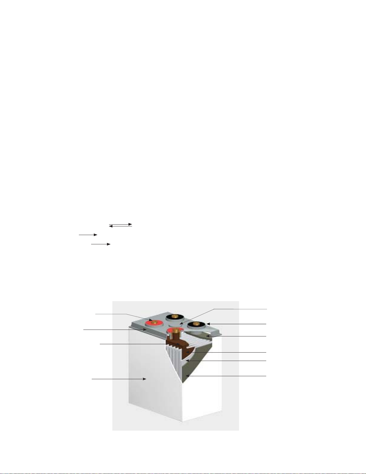
3.0 Specifi cations
Terminal (+)
Cover
Positive Strap
Container
Safety Valve
Terminal (-)
Negative Strap
Positive Plate
Separator
Negative Plate
Fig. 3-1, Battery Construction
8
745-680-B9-001
Page 9

3.0 Specifi cations, continued
3.1 General Specifi cations
Model
SMU 2200-FR
SMU 2300-FR
SMU 2400-FR
SMU2
-500-FR
SMU 2600-FR
SMU 2800-FR
SMU 2-
1000-FR
SMU 2-
1500-FR
SMU 2-
2000-FR
Rated
Voltage
1.80Vpc (C
Rated Capacity (Ah) Dimensions (in/mm)
10hr. to
)
1.80Vpc (C3)
10
3hr. to
1hr. to
1.80Vpc (C1)
Length Width Height
Number
of Poles
2 200 150 110 4.25/120 8/200 15/385 2 35/16
2 300 225 165 6/161 8/200 15/385 2 50/23
2 400 300 220 8/201 8/200 15/385 2 66/30
2 500 375 275 9.5/242 8/200 15/385 2 84/38
2 600 450 330 11/283 8/200 15/385 4 99/45
2 800 600 440 7/183 9.5/244 24.5/629 4 136/62
2 1000 750 550 8.5/218 9.5/244 24.5/629 4 167/76
2 1500 1125 825 12/305 9.5/244 24.5/629 6 244/111
2 2000 1500 1100 14.5/369 9/228 24.25/617 8 337/153
Weight
(lb./Kg)
3.2 Battery Internal Resistance
CAUTION!
Table 3-1, General Specifi cations
Battery internal resistance is a nonlinear parameter that changes with changes in battery
temperature and discharge state. The internal resistance is lowest when the battery is fully
charged. At full charge and 25°C the internal resistances and short circuit currents are as
follows:
Model Internal Resistance (m Ω) Short Circuit Current (A)
SMU 2-200-FR 0.514 3940
SMU 2-300-FR 0.363 5588
SMU 2-400-FR 0.297 6816
SMU2 -500-FR 0.218 9361
SMU 2-600-FR 0.175 11576
SMU 2-800-FR 0.223 9153
SMU 2-1000-FR 0.189 10804
SMU 2-1500-FR 0.152 13237
SMU 2-2000-FR 0.115 17391
Table 3-2, Internal Resistance and Short Circuit Current (25°C)
A short circuit will drop the battery voltage to zero and physically damage its internal components,
poles, and connectors.
745-680-B9-001
9
Page 10

4.0 Temperature, Battery Capacity, and Battery Life
There are several factors that affect the capacity and the life-span of a battery. These include
charging method, discharge depth, end voltages, and ambient temperature. The most signifi cant
of these is temperature. In order to maximize capacity and life-span, ambient temperature should
be controlled and the battery’s fl oat voltage should be set to the appropriate value (for fl oat voltage
specifi cations see section 5.1).
CAUTION!
Excessive temperatures (over 50°C, 120°F) may cause the heat generated in the recombination
process to exceed the rate at which the heat can be transferred out of the battery and thermal
runaway may begin. Thermal runaway is a dangerous cycle that can severely damage equipment.
4.1 Battery Capacity and Ambient Temperature
The capacity of the battery is directly linked to ambient temperature: The lower the
temperature the lower the capacity; the higher the temperature the higher the capacity. The
standard capacity data are based on an optimal 25°C ambient temperature. The effect of
temperature on capacity is as follows:
110
100
90
80
70
Percent of Rated Capacity
60
50
-20 -10 0 10 20 25 30 40 50
Ambient Temperature (°C)
Fig. 4-1, Capacity as a Function of Temperature
10
745-680-B9-001
Page 11

4.0 Temperature, Battery Capacity, and Battery Life, continued
4.2 Battery Life and Ambient Temperature
The expectant life-span of 10+ years is based on a 25°C ambient temperature. Temperatures
above this optimum increase the rate of plate corrosion and of water loss, which shortens
battery life. For temperatures above 25°C, the relationship between temperature and life-span
is expressed in the following equation:
25
/ 2
(T-25)/10
tT = t
Where, tT= the actual life span; T= the actual temperature; t25= the rated life span at 25°C.
For example, if the actual ambient temperature is 35°C then the expectant life-span is 5
years.
NOTE:
While an ambient temperature slightly below 25°C may help the battery reach its potential life-span, it will
not signifi cantly increase that life-span. In addition, the capacity of the battery and it’s ability to discharge
signifi cantly decrease at temperatures below 5°C. The battery’s optimal operating range is 15°C to 25°C.
5.0 Charging
In order to ensure the battery performs to its potential, it is very important that it is:
• Float-charged in order to remain in a fully charged condition
• Completely recharged as soon as possible after a discharge, in order to ensure maximum battery
life
• Charged properly
5.1 Floating Charge Voltage and Ambient Temperature
The fl oat charge keeps the battery in
a fully charged state with a small but
constant current which automatically
covers capacity lost from self and other
discharges.
In order to maximize capacity and life
span, the battery’s fl oat voltage must be
set for the ambient temperature range in
which the battery operates.
CAUTION!
A fl oat voltage set higher than specifi ed accelerates the corruption of the grid, shortens the life
of the battery, and increases the risk of thermal runaway. A fl oat voltage set lower than specifi ed
inhibits the battery from holding a charge; this increases sulfation on the plates, decreases the
capacity and shortens the life of the battery.
Ambient Temperature
(°C)
0–10 2.29
11–15 2.26
16–25 2.23
26–30 2.21
31–35 2.20
36–40 2.19
Table 5-1, Floating Voltage and Temperature
Float Voltage
(Vpc) +/-5%
745-680-B9-001
11
Page 12

5.0 Charging, continued
5.2 Boost Charging
NOTE:
• In general a boost charge should not take more than three hours. If it does, either the batteries or the
charger are likely defective.
• Take and record measurements before and after charging and during discharge to help track changes
and problems. Wait two hours after charging before you take fi nal measurements so the electrolyte can
cool suffi ciently.
The conditions under which the battery needs to be boost charged beyond its fl oat charging
are:
The cell fl oating charge voltage is less than 2.18V.
•
The battery has been in a unused state for more than 3 months.
•
The battery has been running in a state of fl oating charge for over one year.
•
The preferred boost charging method is:
• Charge the battery with a current less than .25 C10A (0.1 C10A to 0.2 C10A is
recommended) at a charge voltage of 2.30 to 2.35 Vpc.
• The charge is fi nished when the current drops to less than 0.006 C10A.
6.0 Maintenance
The SMU battery is maintenance free only in regards to the electrolyte. For assurance of reliability it
is important to perform the recommended periodic maintenance.
WARNING!
To avoid damage to the equipment or injury to the technician, follow these precautions:
• All maintenance work should be performed by a trained technician.
• Remove all jewelry.
• Do not smoke or use fi re near batteries.
• Use insulted tools when installing or maintaining the batteries. Do not lay metal tools on the
batteries.
• Do not remove the safety valves from the batteries or add anything to the batteries.
• Do not clean the batteries with organic cleaners.
• Do not use defective or damaged batteries.
6.1 Monthly Maintenance
• Make sure the battery room is clean.
12
• Measure and record the ambient temperature of the battery room.
• Make sure the batteries are clean.
• Check for damage, or evidence of over-heating on the terminals, containers, and lids.
• Measure and record the total voltage and fl oating current of the battery system.
745-680-B9-001
Page 13

6.0 Maintenance, continued
6.2 Quarterly Maintenance
• Repeat monthly inspection.
• Measure and record the fl oating voltage of every cell. If more than two cells’ voltages are
less than 2.18V, the batteries need to be boost charged (see Section 5.2). If the problem
persists, conduct annual and then three-year maintenance.
6.3 Yearly Maintenance
• Repeat quarterly maintenance and inspection.
• Ensure all connections are clean and tight.
• Check the load of the batteries by conducting a capacity (discharge) test: discharge the
batteries to between 30% and 40% of rated capacity.
6.4 Three-year Maintenance
• Conduct a capacity (discharge) test. Replace any battery with a capacity less than 80%
of rated capacity.
7.0 Storage
Storage procedures:
• Before storing, fully charge the batteries. Storing a battery in a discharged state will negatively
affect its life span and capacity.
• All lead acid batteries experience self-discharge in open circuit. The self-discharge rate is largely
determined by ambient temperature: the lower the temperature, the lower the discharge rate
and the higher the temperature, the higher the discharge rate. Store batteries in a clean, well
ventilated location with temperatures between 0°C and 35°C.
• In order to avoid permanent damage to the plate caused by self-discharge, the batteries should
be boost charged after every three months in storage (see section 5.2).
• Record all dates and services performed. See page 22 for form.
745-680-B9-001
13
Page 14

8.0 Installation
About the site:
Maintain a distance of at least 20" (508mm) between the battery and electrical switches and
•
outlets.
Do not expose the battery to organic solvents and corrosive gasses.
•
Maintain a distance of at least 7.87" (200mm) between batteries and battery groups to provide
•
proper ventilation.
Create a pathway at least 47.24" (1200mm) wide next to each battery group for access during
•
routine maintenance.
Verify that the maximum weight capacity of the fl oor is not exceeded.
•
The ideal operating temperature is 77ºF (25ºC). If possible, install air-conditioning or forced
•
ventilation to keep temperatures between 59ºF (15ºC) and 95ºF (30ºC).
CAUTION!
All the cells in the system must be of the same capacity. Alpha recommends the cells be close in
age.
Tools needed:
• Socket and wrench sets
• Torque wrench
Procedure:
1. Check the cells and frame modules for damage. Do not install damaged cells.
2. Remove the retaining bars and the cells from the frame modules.
3. Fasten the two channel bars to one module with M8x30 bolts, nuts, fl at washers, and lock
washers. The bigger diameter holes on the channel bars should face down for anchoring to the
fl oor. The channel bars can be mounted with their open side facing either in or out depending on
installation and maintenance convenience.
4. Fasten the second frame module to the top of the fi rst with four M8x20 bolts, nuts, fl at washers,
and lock washers. Continue stacking and fastening together modules. Alpha recommends
stacking no more than four modules. However, the system can accommodate up to six. If
applicable, blot parallel stacks to each other with two bolts, one in the front and one in the back,
on each row.
5. Torque all nuts to 130 in/lb. (15N/m).
6. Fasten the two lead terminals to the top module. One terminal can be fastened to each side of the
module or both can be fastened to the same side.
7. Starting with the bottom module (to prevent tipping), slide the battery cells into the assembled
frame. Orient the positive and negative poles of the batteries as shown in Fig 8-3.
8. Fasten the retaining bars to the modules to secure the cells.
9. Connect the cells using the fl exible connectors according to color and polarity (red=positive;
blue=negative), as shown in Figures 8-2 and 8-3. Torque all connections to 130 in/lb. (15N/m).
10. Check the voltage and polarity of the battery string with a voltameter.
11. Connect the positive poles of the cell at one end of the string to the positive terminal. Connect the
negative poles of the cell on the other end of the string to the negative terminal (see Fig. 8-3).
CAUTION!
Take care not to create a short circuit when connecting the battery string to the lead terminals.
12. Install the plastic terminal covers to the terminals and the cover plate to the top of the top module.
14
745-680-B9-001
Page 15

8.0 Installation, continued
Cover Plate
Plastic Terminal Cover
Lead Terminal
(one of two)
Module 2
M8x20 Bolts
M8x30 Bolts
Channel Bar
Module 1
Fig. 8-1, Frame Construction
Positive Lead Terminal
Negative Lead Terminal
Plastic Terminal Cover
8mm Allen Bolt
Washer
Fig. 8-2, Battery Connector Detail
745-680-B9-001
Connector
Terminal Post
Fig. 8-3, Sample Battery Installation (SMU-500)
15
Page 16

9.0 Appendix A, Specifi cations
Voltage
Time (h)
Fig. 9-1, Discharge Performance
2.1
2.0
1.9
Voltage
1.8
1.7
1.6
0.0 0.2 0.4 0.6 0.8 1.0 1.2 1.4 1.6
Discharge Rate K
(Kch=I
ch
dis/C10
)
Fig. 9-2, Discharge Curve at One Minute (25°C)
16
745-680-B9-001
Page 17

9.0 Appendix A: Specifi cations, continued
2.1
2.0
1.9
Voltage
1.8
1.7
1.6
0.0 0.2 0.4 0.6 0.8 1.0 1.2 1.4 1.6
Discharge Rate Kch (Kch= I
dis/C10
)
Fig. 9-3, Discharge Curve at Five Seconds (25°C)
3
2.
2.2
2.1
2.0
1.9
Voltage
1.8
1.7
1.6
1.5
0.0 0.5 1.0 1.5 2.0 2.5 3.0
Discharge Rate Kch (Kch= I
dis/C10
)
Float Voltage
Open Circuit
0.1 C
10
0.2 C
10
0.3 C
10
0.4 C
10
0.5 C
10
745-680-B9-001
Fig. 9-4, Shock Discharge Curve at Different Rates after Discharge of One Hour (25°C)
17
Page 18

9.0 Appendix A: Specifi cations, continued
2.1
2.0
1.9
1.8
Voltage
1.7
1.6
1.5
0.0 0.5 1.0 1.5 2.0 2.5 3.0
Discharge Rate Kch (Kch= I
dis/C10
)
Fig. 9-5, Shock Discharge Curves at Different Rates After .5h Discharge (25°C)
Charge current of 0.1C10A and a voltage limit of 2.35Vpc (25°C).
4
60
50
40
2.
Voltage
Current
2.3
Capacity Charged
2.2
0.1 C
0.2 C
0.3 C
0.4 C
0.5 C
1.
1.2
1.0
0.8
10
10
10
10
10
4
18
30
Current
20
10
0
2.1
Voltage
2.0
1.9
0 4 8 12162024
Time (h)
Fig. 9-6, Recharge Characteristics of a 100% discharged SMU-500.
0.6
0.4
Capacity Charged Rate
0.2
0.0
745-680-B9-001
Page 19

9.0 Appendix A: Specifi cations, continued
50
40
30
20
Current
10
0
Charge current of 0.1C10A and a voltage limit of 2.23Vpc (25°C).
Voltage
Capacity Charged
2.
2.1
Current
2
Voltage
2.0
1.9
04812162024
Time (h)
Fig. 9-7, Recharge Characteristics of a 100% discharged SMU-500.
1.
3
1.2
1.1
1.0
0.9
0.8
0.7
0.6
0.5
0.4
Capacity Charged Rate
0.3
0.2
0.1
0.0
End Discharge Voltage 1.75/Cell (Amps)
Typ e Mi nute s Hours
5101520304050609023456789101224
SMU 2-200-FR
SMU 2-300-FR
SMU 2-400-FR
SMU 2-500-FR
SMU 2-600-FR
SMU 2-800-FR
SMU 2-1000-FR
SMU 2-1500-FR
SMU 2-2000-FR
End Discharge Voltage 1.80/Cell (Amps)
Typ e Mi nute s Hours
SMU 2-200-FR
SMU 2-300-FR
SMU 2-400-FR
SMU 2-500-FR
SMU 2-600-FR
SMU 2-800-FR
SMU 2-1000-FR
SMU 2-1500-FR
SMU 2-2000-FR
277.1 252.8 233.3 213.2 171.0 148.0 128.8 114.0 86.4 70.6 52.4 42.8 3 6.4 32.0 28.3 25. 5 23.2 21.2 18.0 9.8
415.6 379.2 350.0 319.7 256.5 222.0 193.2 171.0 129.6 106 .0 78.6 64.2 54.6 48.0 42.5 3 8.2 34.7 31.9 27.0 14.6
554.1 505.6 466.7 426.3 342.0 29 6.0 257.6 228.0 172. 8 141.3 104.8 85.6 72.8 64.0 56.6 51.0 4 6.3 42.5 36.0 19.5
692.6 6 32.1 583.3 532.9 427.5 370.0 322.0 285.0 216.0 176.6 131.0 107.0 91.0 80.0 70.8 63.7 57.9 53.1 45.0 24.4
831.1 758.5 700.0 639.5 513.0 444.0 386.4 342.0 259. 2 211.9 157.2 128.4 109.2 96.0 85.0 76.4 69.5 63.7 54.0 29.3
972.7 897.9 825.4 755.7 615.2 547.2 491.2 446.4 349.9 292.8 216.0 174.2 147.2 127.3 112.3 101.1 92.0 84.3 72. 4 39.2
1215.8 1122.4 1031.7 94 4.6 769.0 684.0 614.0 558.0 4 37.3 36 6.0 270.0 217.8 184.0 159.1 140. 4 126.4 115.0 105.4 90.5 4 9.0
1823.8 168 3.6 1547.5 1416.9 1153.5 1026.0 921.0 837.0 656.0 5 49.0 40 5.0 326.6 276.0 238 .7 210.6 189.6 172.5 158.1 135.8 73.4
2431.7 2244.8 2063.4 1889.2 1538.0 1368.0 1228.0 1116.0 874.7 732.0 540.0 435. 5 368.0 318.2 280.9 252.8 23 0.0 210.8 181.0 97.9
5101520304050609023456789101224
266.5 240.2 220.0 201.1 160.0 137.2 120.0 106. 8 81.4 67.6 50. 8 41.4 35.6 31.2 27.8 25.0 22.7 20.8 17.6 9.6
399.7 36 0.3 330.0 301.6 240.0 205.8 180.0 160.2 122.1 101.4 76.2 62.0 53.3 46.8 41.8 37.5 3 4.0 31.1 26. 3 14.4
533.0 4 80.4 440.0 402.1 320.0 274.4 240.0 213.6 162.8 135. 2 101.6 82.7 71.1 62.4 55.7 50.0 45.4 41.5 3 5.1 19.2
666. 2 600.5 550.0 502.6 40 0.0 343.0 300.0 267.0 203.5 169.0 127.0 103.4 88.9 78.0 69.6 62.5 56.7 51.9 43.9 24.0
799.5 720.5 660.0 603.2 480.0 411.6 360.0 320.4 244.2 202 .8 152.4 124.1 106.7 93.6 83.5 75.0 68.0 62.3 52.7 28.8
918.9 841.1 769.7 697.9 576.0 519.2 460.8 424.0 336.0 284.0 211.2 171.2 143.8 124.8 110.5 99.2 90.8 83. 2 71.6 38.3
1148.6 1051.4 962. 2 872.4 720.0 649.0 576.0 53 0.0 420.0 355.0 264.0 214.0 179.8 156.0 138.1 124.0 113.4 104.0 89. 5 47.9
1723.0 1577.0 1443.2 1308.5 1080.0 973.5 864.0 795.0 630.0 532.5 39 6.0 321.0 26 9.7 234.0 207.2 186.0 170.2 156.0 134.3 71.9
2297.3 2102.7 1924.3 1744.7 1440.0 1298.0 1152.0 1060.0 840.0 710.0 528.0 428.0 359.6 312.0 276.3 24 8.0 226.9 208.0 179.0 95.8
745-680-B9-001
Table 9-1, Discharge Specifi cations
19
Page 20

10.0 Appendix B: Choosing the Right Capacity
10.1 Telecom Applications
Discharge Time
+RXU0LQXWH
Discharge Current (A)
Fig. 10-1, Single Cell Discharge Curves (Final Voltage: 1.80 Vpc; 25°C)
10.2 Power Applications
1.1
1.0
0.9
0.8
)
0.7
10
0.6
0.5
0.4
Capacity (C/C
0.3
0.2
0.1
0.0
110
1
2
3
4
Discharge Time (h)
End Voltage
1 1.60
2 1.70
3 1.80
4 1.90
1.1
1.0
0.9
0.8
0.7
0.6
0.5
0.4
0.3
0.2
0.1
0.0
5
20
Fig. 10-2, Curves With Stairs Loading Calculation Method (25°C)
745-680-B9-001
Page 21

10.0 Appendix B: Choosing the Right Capacity, continued
0
10.2 Power Applications, continued
1.3
1.2
4
3
1.1
2
End Voltage
1 1.90
1
2 1.80
3 1.70
4 1.60
/C
discharge
= I
Ch
K
1.0
0.9
0.8
0.7
0.6
0.5
0.4
0.3
0.2
0.1
0.0
0 60 120 180 240 300 360 420 48
Time (min)
Fig. 10-3, Curves with Voltage Control Method (25°C)
745-680-B9-001
21
Page 22

11.0 Forms
Charging Recording Form
Record before charging and two hours after
Model of Battery
Battery Bank No.
Charging Current
Remarks
Cell # Voltage Siemans Conductance Rating Notes
Date
Room Temperature
Total Battery Voltage
NOTE:
Wait two hours after charging before you take fi nal measurements so the electrolyte can cool suffi ciently.
22
745-680-B9-001
Page 23

11.0 Forms, continued
Discharge Recording Form
Model of Battery
Battery No.
Charging Current
Remarks
Cell # Initial
Voltage
Date
Room Temperature
Total Battery Voltage
Cell Voltage at Time Period End
15min 30min 1hr 2hr 3hr 4hr 4:30hr 5 hr
745-680-B9-001
23
Page 24

Alpha Technologies
Power
®
Alpha Technologies
3767 Alpha Way
Bellingham, WA 98226
USA
Tel: +1 360 647 2360
Fax: +1 360 671 4936
Web: www.alpha.com
Alpha Technologies Ltd.
4084 McConnell Court
Burnaby, BC, V5A 3N7
CANADA
Tel: +1 604 430 1476
Fax: +1 604 430 8908
Alpha Technologies
Europe Ltd.
Twyford House
Thorley
Bishop's Stortford
Hertfordshire
CM22 7PA
UNITED KINGDOM
Tel: +44 0 1279 501110
Fax: +44 0 1279 659870
Alpha Technologies GmbH
Hansastrasse 8
D 91126 Schwabach
GERMANY
Tel: +49 9122 79889 0
Fax: +49 9122 79889 21
Alphatec, Ltd
P.O. Box 56468
Limassol, Cyprus
CYPRUS
Tel: +357 25 375675
Fax: +357 25 359595
AlphaTEK ooo
Khokhlovskiy Pereulok 16
Stroenie 1, offi ce 403
109028 Moscow
RUSSIA
Tel: +7 495 916 1854
Fax: +7 495 916 1349
Alphatec Baltics
S. Konarskio G. 49
Vilnius 2009
LITHUANIA
Tel: +370 5 2138822
Fax: +370 5 2137799
Alpha Technologies
5 Avenue Victor Hugo
F 92140 Clamart France
FRANCE
Tel: +33 1 41 90 07 07
Fax: +33 1 41 90 93 12
Copyright © 2007 Alpha Technologies, Inc. All rights reserved. Alpha is a registered trademark of Alpha Technologies. 745-680-B9-001 Rev. A.
Due to continuing product improvements, Alpha reserves the right to change specifi cations without notice.
 Loading...