

Page 1
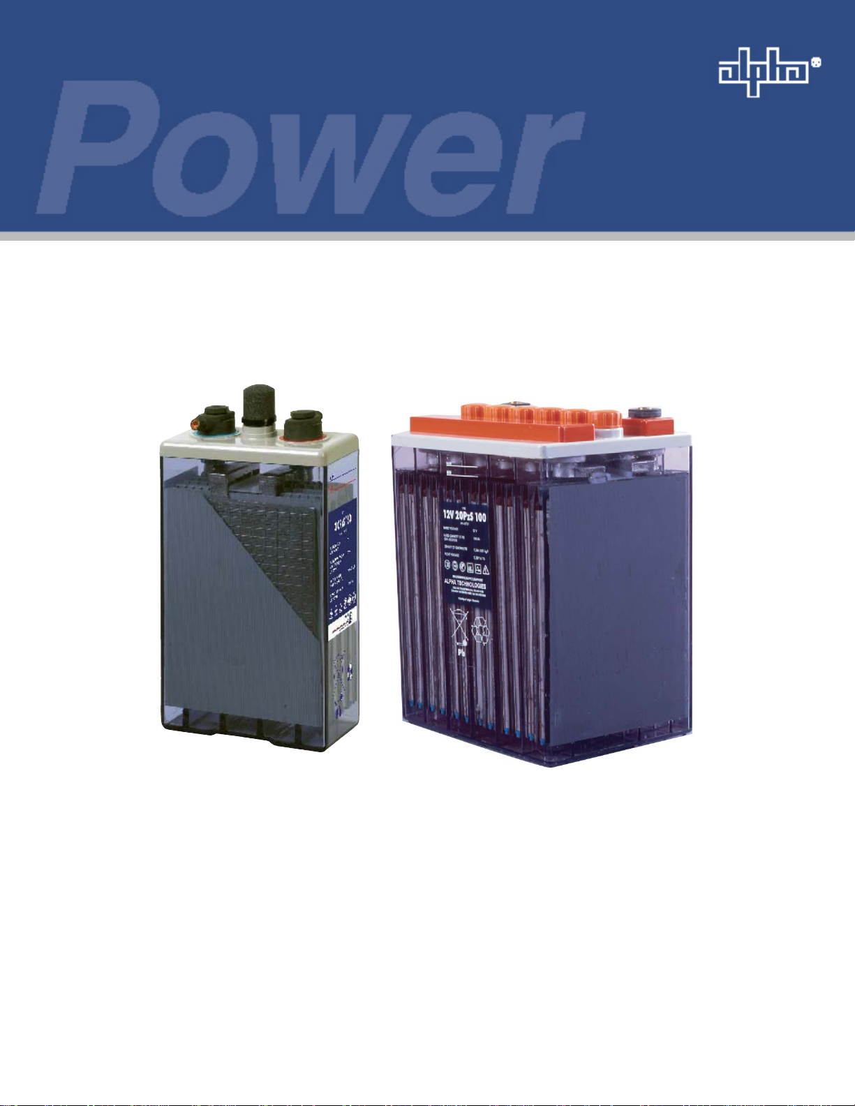
AlphaCell OPzS
Stationary Flooded Tubular Lead-acid Batteries
Technical Manual
AlphaCell OPzS Battery
Effective: January 2008
Alpha Technologies
Page 2

Alpha Technologies
Power
®
Page 3

AlphaCell OPzS Battery
Installation and Operation Manual
OPzS-BATTERY
Effective Date: January 2008
Copyright© 2008
Alpha Technologies, Inc.
A Member of the Alpha Group
NOTE:
Photographs contained in this manual are for illustrative purposes only. These photographs may not match
your installation.
NOTE:
Operator is cautioned to review the drawings and illustrations contained in this manual before proceeding. If
there are questions regarding the safe operation of this powering system, please contact Alpha Technologies
or your nearest Alpha representative.
NOTE:
Alpha shall not be held liable for any damage or injury involving its enclosures, power supplies, generators,
batteries, or other hardware if used or operated in any manner or subject to any condition not consistent with
its intended purpose, or is installed or operated in an unapproved manner, or improperly maintained.
Contacting Alpha Technologies: www.alpha.com
or
For general product information and customer service (7 AM to 5 PM, Pacifi c Time), call
1 800 863 3930
For complete technical support, call
OPzS-BATTERY
1 800 863 3364
7 AM to 5 PM, Pacifi c Time or 24/7 emergency support
3
Page 4

Table of Contents
Safety Notes .......................................................................................................................... 8
Battery Safety Notes.............................................................................................................. 9
Chemical Hazards ................................................................................................................. 9
Recycling and Disposal Instructions ...................................................................................... 9
1.0 General Information .................................................................................................. 10
1.1 Introduction .................................................................................................... 10
1.2 Precautions .................................................................................................... 10
2.0 Safety.........................................................................................................................11
2.1 General ...........................................................................................................11
2.2 Safety Equipment and Clothing ......................................................................11
2.3 Safety Precautions ..........................................................................................11
2.3.1 Sulfuric Acid Burns ...............................................................................11
2.3.2 Explosive Gases and Fire ................................................................... 12
2.3.3 Electrical Shocks and Burns ............................................................... 12
3.0 Inspecting the Battery Shipment ............................................................................... 13
3.1 General .......................................................................................................... 13
3.2 Visible External Damage ................................................................................ 13
3.3 Concealed Damage ....................................................................................... 13
4.0 Battery Storage Before Installation ........................................................................... 14
4.1 General .......................................................................................................... 14
4.2 Storage Interval.............................................................................................. 14
4.2.1 Filled and charged cells ...................................................................... 14
4.2.2 Dry charged cells ................................................................................ 14
4.3 Advanced Preparation ................................................................................... 14
5.0 Selection and Accommodation Considerations ........................................................ 15
5.1 General .......................................................................................................... 15
5.2 Battery Selection ............................................................................................ 15
5.3 Accommodation Considerations .................................................................... 15
4
OPzS-BATTERY
Page 5

Table of Contents, continued
6.0 Unpacking and Handling for Installation ................................................................... 16
6.1 General .......................................................................................................... 16
6.2 Recommended Installation Equipment and Supplies .................................... 16
6.3 Cell Handling.................................................................................................. 16
7.0 System Installation.................................................................................................... 17
7.1 General .......................................................................................................... 17
7.2 System Layout ............................................................................................... 17
7.3 Installation Considerations ............................................................................. 17
7.3.1 Arrangement ....................................................................................... 17
7.3.2 Spacing ............................................................................................... 18
7.4 Battery Installation ......................................................................................... 18
7.5 Preparing and Installing Connections ............................................................ 19
7.5.1 Terminal Posts ..................................................................................... 19
7.5.2 Intercell Connectors ............................................................................ 20
7.5.3 Terminal Plates .................................................................................... 20
8.0 Battery Taps .............................................................................................................. 21
9.0 Pilot Cell.................................................................................................................... 21
10.0 Freshening Charge .................................................................................................. 22
11.0 Operation ................................................................................................................. 23
11.1 Battery Charging and Operation Mode .......................................................... 23
11.1.1 Charging.............................................................................................. 23
11.1.2 Floating operation ............................................................................... 23
11.1.3 Switch mode operation........................................................................ 24
11.1.4 Battery charge/discharge operation .................................................... 24
11.2 Hydrometer Readings - Specifi c Gravity ........................................................ 24
11.3 Equalizing Charge.......................................................................................... 24
11.3.1 Equalizing Charge Method .................................................................. 25
11.4 Operating Temperature .................................................................................. 25
OPzS-BATTERY
5
Page 6

Table of Contents, continued
12.0 Maintenance ............................................................................................................ 26
12.1 Battery Cleaning ............................................................................................ 26
12.1.1 Standard Cleaning .............................................................................. 26
12.1.2 Corrosion Cleaning ............................................................................. 26
12.1.3 Heavy Corrosion Cleaning .................................................................. 27
12.1.4 Cleaning Flame Arrestors.................................................................... 27
12.1.5 Replacing or Isolating a Cell ............................................................... 27
12.2 Maintenance Records .................................................................................... 28
12.3 Corrective Actions .......................................................................................... 29
12.4 Adding Water ................................................................................................. 30
12.5 Quality of Water ............................................................................................. 30
12.6 Filling Dry-Charged Cells ............................................................................... 31
13.0 Test Procedures ....................................................................................................... 32
13.1 Procedure for Battery Capacity Tests ............................................................ 32
14.0 Specifi cations........................................................................................................... 33
15.0 Battery Room Ventilation Calculation ...................................................................... 42
16.0 Maintenance Records .............................................................................................. 43
6
OPzS-BATTERY
Page 7

Figures and Tables
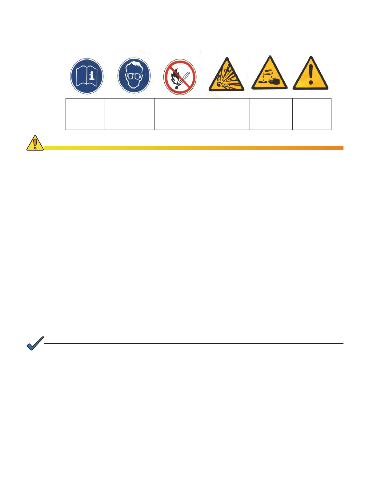
Fig. 2-1, Safety Labels..........................................................................................................11
Fig. 16-1, Charged Battery Readings Before Discharge Begins Form ................................ 43
Fig. 16-2, After “Load Profi le” Battery Form......................................................................... 44
Fig. 16-3, “Final Recharge” Battery Readings Form............................................................ 45
Table 14-1, OPzS Dimensions............................................................................................. 33
Table 14-2, OPzS General Specifi cations ........................................................................... 34
Table 14-3, OPzS Capacity ................................................................................................. 34
Table 14-4, Discharge Current (1.83Vpc End Voltage) ....................................................... 35
Table 14-5, Discharge Current (1.80Vpc End Voltage) ....................................................... 36
Table 14-6, Discharge Current (1.75Vpc End Voltage) ....................................................... 37
Table 14-7, Discharge Current (1.70Vpc End Voltage) ....................................................... 38
Table 14-8, Sulphuric Acid Impurities .................................................................................. 39
Table 14-9, Demineralized Water Impurities ........................................................................ 40
Table 14-10, List of Reference Standards ........................................................................... 40
Table 14-11, Total Gas Emission for OPzS Batteries after 10 years of Operation ............... 41
Table 14-12, Internal Resistance and Short Circuit Currents (2 Volts) ................................ 42
OPzS-BATTERY
7
Page 8

Safety Notes
Review the drawings and illustrations contained in this manual before proceeding. If there are any questions
regarding the safe installation or operation of the system, contact Alpha Technologies or the nearest Alpha
representative. Save this document for future reference.
To reduce the risk of injury or death, and to ensure the continued safe operation of this product, the following
symbols have been placed throughout this manual. Where these symbols appear, use extra care and
attention.
ATTENTION:
The use of ATTENTION indicates specifi c regulatory/code requirements that may affect the placement of
equipment and installation procedures.
NOTE:
A NOTE provides additional information to help complete a specifi c task or procedure.
CAUTION!
The use of CAUTION indicates safety information intended to PREVENT DAMAGE to material or
equipment.
WARNING!
A WARNING presents safety information to PREVENT INJURY OR DEATH to the
technician or user.
8
OPzS-BATTERY
Page 9

Battery Safety Notes
WARNING!
Lead-acid batteries contain dangerous voltages, currents and corrosive material. Battery
installation, maintenance, service and replacement must be performed only by authorized
personnel.
Chemical Hazards
Any liquid leakage from a fl ooded lead-acid battery contain dilute sulfuric acid, which is harmful to the skin
and eyes. Emissions are electrolytic, and are electrically conductive and corrosive.
To avoid injury:
•
The servicing and connection of batteries shall be performed by, or under the direct supervision of, personnel
knowledgeable of batteries and required safety precautions.
•
Always wear eye protection, rubber gloves, and a protective vest when working near batteries. Remove all metallic
objects from hands and neck.
•
Batteries produce explosive gases. Keep all open fl ames and sparks away from batteries.
•
Use tools with insulated handles, do not rest any tools on top of batteries.
•
Lead-acid batteries contain or emit chemicals known to the State of California to cause cancer and birth defects or
other reproductive harm. Battery post terminals and related accessories contain lead and lead compounds. Wash
hands after handling (California Proposition 65).
•
Wear protective clothing (insulated gloves, eye protection, etc.) when installing, maintaining, servicing, or replacing
batteries.
•
If any battery emission contacts the skin, wash immediately and thoroughly with water. Follow your company’s
approved chemical exposure procedures.
•
Neutralize any spilled battery emission with the special solution contained in an approved spill kit or with a solution
of one pound bicarbonate of soda to one gallon of water. Report a chemical spill using your company’s spill reporting
structure and seek medical attention if necessary.
•
Always replace batteries with those of an identical type and rating. Never install old or untested batteries.
•
Do not charge batteries in a sealed container. Each individual battery should have at least 0.5 inches of space
between it and all surrounding surfaces to allow for convection cooling.
•
All battery compartments must have adequate ventilation to prevent accumulation of potentially dangerous gas.
Ventilation should prevent trapped hydrogen gas pockets from exceeding a 1% concentration as per regulation 70E
of the National Fire Protection Agency (NFPA).
•
Prior to handling the batteries, touch a grounded metal object to dissipate any static charge that may have developed
on your body.
•
Never use uninsulated tools or other conductive materials when installing, maintaining, servicing, or replacing
batteries.
•
Use special caution when connecting or adjusting battery cabling. An improperly connected or unconnected battery
cable can make contact with an unintended surface resulting in arcing, fi re, or possible explosion.
•
A battery showing signs of cracking, leaking, or swelling should be replaced immediately by authorized personnel
using a battery of identical type and rating.
Equipment Cautions
Do not operate NiCd and lead-acid batteries in the same room. NiCd emissions will neutralize the lead-acid solution,
•
rendering the battery useless.
Overcharging the battery can result in a loss of capacity and excess release of gas.
•
Recycling and Disposal Instructions
Spent or damaged batteries are considered environmentally unsafe. Always recycle used batteries or dispose of the
batteries in accordance with all federal, state and local regulations.
OPzS-BATTERY
9
Page 10

1.0 General Information
1.1 Introduction
OpzS batteries are intended for telecommunication facilities, computers, emergency lighting,
alarm, control and monitoring systems in power plants and distribution stations, railway
stations, airports etc. Due to their extremely low self-discharge rate they are also suitable for
plants supplied by solar cells.
When properly handled and operated stationary OpzS batteries do not represent any danger
or harm for the operators and environment. When handling take into account all safety and
operating instructions.
1.2 Precautions
Before unpacking, storing, handling, installing, operating, or performing maintenance on the
battery system read the following information thoroughly.
It is important to read, understand and strictly follow the instructions in this manual.
If the following precautions are not fully understood, or if local conditions are not covered,
contact the manufacturer for clarifi cation or ask for technical advice.
Refer to all applicable state and local regulations and industry standards.
NOTE:
You should be trained in handling, installing, operating and maintaining batteries before you work on any
battery system.
10
.
OPzS-BATTERY
Page 11
2.0 Safety
Follow
Instructions
CAUTION!
If you have any questions concerning safety, contact your local manufacturer sales representative to clarify
any of the noted safety precautions or call the Alpha Customer Service number listed on the back of this
manual.
Use Protective
Goggle and
Clothes
Avoid Sparks,
Flames, or
Arcing
Fig. 2-1, Safety Labels «
Explosive
Gases
(Avoid Short
Circuit
Caustic Acid Danger
2.1 General
Like all other fl ooded, lead-acid batteries, OPzS stationary batteries may leak, release
hydrogen gas or cause acid misting. Always follow the generally accepted safety procedures
for handling batteries. In addition, it is very important that the precautions recommended in
this manual are observed.
You must understand the risk of working with batteries and be prepared to take the necessary
safety precautions.
2.2 Safety Equipment and Clothing
When working with any battery system, be sure you have the necessary tools and safety
equipment, including but not limited to: insulated tools, face shield and protective goggles,
rubber apron or acid resistant cloth, rubber gloves, emergency eye wash and shower, fi re
extinguisher and acid spill cleanup kit.
Always:
Remove all jewelry (i.e., rings, watches, chains, etc.).
•
Keep sparks, fl ames and smoking materials away from the battery.
•
Never lay tools or other metallic objects on the battery cell. Using the correct tools and
wearing proper safety equipment will help prevent injury should an accident occur.
NOTE:
In case of a sulfuric acid spill, bicarbonate of soda or an emergency spill kit should be within the battery room.
2.3 Safety Precautions
2.3.1 Sulfuric Acid Burns
Stationary batteries are safe when operated and handled properly. However, they do
contain sulfuric acid, which can cause burns and other serious injuries. Always wear
protective clothing.
In case of contact with skin or cloth, immediately:
Remove contaminated clothing.
•
Flush the area thoroughly with water.
•
Get medical attention, if required.
•
OPzS-BATTERY
11
Page 12

2.0 Safety, continued
2.3 Safety Precautions, continued
2.3.1 Sulfuric Acid Burns, continued
In case of eye contact with sulfuric acid, immediately:
•
•
If acid is spilled it should be neutralized with a solution of 1 pound of baking soda to 1
gallon of water (1 kg NaHCO3 / 10 l water) and then washed off with water.
2.3.2 Explosive Gases and Fire
Batteries generate explosive gases in all stages of operation. Under extreme
conditions these gases can explode, causing blindness and other serious personal
injury. Consider the following:
•
•
•
•
In case of fi re:
Flush thoroughly every few minutes with large amounts of water.
Get medical attention.
Always wear protective clothing and use the correct safety tools.
Eliminate any potential of sparks, fl ames or arcing.
Before working on the battery, be sure to discharge static electricity that can build
up on tools or the technician by touching a grounded surface in the vicinity of the
battery but far enough from the cells and fl ame arresters to avoid ignition of any
hydrogen gas present.
Provide adequate ventilation of the battery room.
If batteries are connected to a charger, shut off power.
•
Extinguish a fi re in a battery room containing lead acid batteries, using CO2,
•
foam, or dry chemical extinguishing media. Do NOT discharge the extinguisher
directly onto the battery. The resulting thermal shock may cause cracking of the
battery case/cover.
Leave the area as soon as possible if toxic fumes are present.
•
Wear breathing apparatus if it is required to remain in the area.
•
2.3.3 Electrical Shocks and Burns
Multi-cell battery systems can attain high voltage and/or currents, therefore, do not
touch un-insulated battery connectors or terminals. To prevent serious electrical
shock and burns, use extreme caution when working with the system.
Always wear protective clothing and use nonconductive or insulated tools when
working with any battery system.
Remove any jewelry or clothing that could produce a short circuit between the
positive and negative terminal of a battery or battery string.
Before working on the system:
Disconnect all loads and power sources to the battery.
•
If working on an assembled battery system, sectionalize (interrupt the battery
•
sections) into safe working voltage levels.
Check the battery system grounding. Grounding of the battery system is not
•
recommended. However, grounding of the rack is recommended.
Should you be required to work on a grounded battery system, make absolutely sure
you use the correct safety precautions, equipment and clothing.
12
OPzS-BATTERY
Page 13

3.0 Inspecting the Battery Shipment
3.1 General
Precautions have been taken to pack the cells/battery units for shipment to ensure its safe
arrival. However, upon receipt, you should inspect for evidence of damage that may have
occurred during transit.
WARNING!
During inspections, take precautions against electrical shock. You are handling live
batteries.
3.2 Visible External Damage
Inventory all materials against the bill of lading and inspect for visible external damage.
Check material quantities received including the number of battery pallets and the number of
accessory boxes.
Note any damage to packing material and wetness or stains, indicating electrolyte leakage
and contact the manufacturer.
3.3 Concealed Damage
Within 15 days of receipt (or as soon as practical), unpack the cells. Check the received
materials against the detailed packing list to verify receipt of all materials in the quantities
specifi ed and check for concealed damage.
Examine the electrolyte level to ensure that none has been spilled. If electrolyte has been lost
in transit and no damage is established which can cause leak add sulfuric acid electrolyte of
the nominal operating specifi c gravity indicated on the cell nameplate, and bring to the low
level line on open circuit.
If damage is noted fi le a claim for concealed damage.
If cells are shipped charged and dry with separate electrolyte, fi ll only when ready to place in
service.
DELAY IN NOTIFYING MAY RESULT IN LOSS OF YOUR RIGHT TO REFUND FOR
DAMAGES.
If you have questions concerning potential damages, contact the manufacturer’s sales
representative or Alpha Technologies Customer Service.
OPzS-BATTERY
13
Page 14

4.0 Battery Storage Before Installation
4.1 General
Batteries should be unpacked, installed and charged as soon as possible after receipt.
However, if this is impractical, follow the instructions below for storing the battery before
installation.
Stationary battery cells can be fi lled with electrolyte and charged - fl ooded or dry-charged.
Store batteries indoors in a clean, dry, cool and frost free location (10 °C – 30 °C). Storage
at higher temperatures will result in accelerated rates of self-discharge and possible
deterioration of battery performance and life.
Do not stack pallets. Damage may occur and the warranty will be voided.
4.2 Storage Interval
4.2.1 Filled and charged cells
Filled and charged cells should be recharged every 90 days to prevent their failure.
Use the date of battery shipment to determine freshening charge requirements.
Storage times exceeding the above may result in plate sulfation, which may
adversely affect electrical performance and expected life.
4.2.2 Dry charged cells
Dry charged cells may stand for a longer time as long as they are sealed and stored
with as little temperature variations as possible within 24 hours (< 30 °C, < 50 % H).
In the winter the storage room should be safe from freezing.
Maximum total storage time before installation is 2 years from the date of shipment
from the factory to the customer.
4.3 Advanced Preparation
If storage time is likely to be exceeded, make advanced preparation to have an adequate
charger available and adjacent to an appropriate AC supply voltage. Positioning of the cells
to accept the temporary intercell connectors is another consideration of advance planning.
Make every effort to get the battery connected to the charger before the expiration of the
storage period.
NOTE:
Failure to charge as noted voids the battery warranty.
14
OPzS-BATTERY
Page 15

5.0 Selection and Accommodation Considerations
5.1 General
If you have any questions concerning the battery selection and installation considerations,
contact your local manufacturer’s representative or Alpha Technologies Customer Service.
5.2 Battery Selection
To correctly match your battery needs with the correct battery, please consider the following
information:
•
Type of consuming device (telephone plant, DC-AC converter, emergency lighting etc).
•
Operating energy of the consumer (kW, kVA, cosf).
•
Minimum and maximum allowable rated voltage at consuming device (V).
•
Time diagram of a consumer load, and the required time autonomy (reserve).
•
Expected voltage drop in the supply lines - surrounding temperature in the battery room
(average, minimum, maximum).
•
Type of rectifi er, its characteristics, regulating point I (A) or U (V), respectively, fl oat
voltage (V) (direct voltage of rapid-charging current Imax (A), fl oat charging voltage).
•
Outline or dimensions of the battery room.
•
Type of installation (welded, bolted, on wooden or metal racks, in case, on earthquakeproof racks).
•
Battery maintenance accessories (V-meter, areometer (hygrometer), thermometers).
5.3 Accommodation Considerations
When planning the system accommodation for fl ooded stationary batteries consider following:
Space: The aisle space provided in front of all racks should be a minimum of 36 inches (915
mm), where this dimension is not in confl ict with any local codes or regulations. A minimum
of 9 inches (230 mm) is desirable above the tops of the cell posts of the top row of cells
to permit access for maintenance or cell removal. Each cell should be accessible for the
addition of water and for taking individual cell voltage and hydrometer readings.
Environment: Clean, cool and dry. A location should be selected which keeps water, oil and
dirt away from all cells.
Temperature: Recommended ambient temperature shall be between 50°F and 86°F (10 °C
to 30 °C). Elevated temperatures reduce operating life. Lower temperatures reduce battery
performance. Minimize temperature variations between the cells. To avoid temperature
variation between the cells, do NOT locate the battery near HVAC ducts or exhausts, heat
sources (i.e., equipment that generates heat) or direct sunlight.
Ventilation: Adequate ventilation must be provided, so as to prevent hydrogen gas from
exceeding explosive concentration. Ventilation must be adequate to ensure that pockets of
trapped hydrogen gas do not develop, particularly at the ceiling. Also refer to EN 50272-2 or
IEEE 484 for determining ventilation requirements.
Grounding: It is recommended that the racks be grounded. Also refer to national/local codes.
Codes: Refer to national/local building codes and fi re codes.
Floor: The fl oor of the battery room should be made of an acid-resistant material, such as
asphalt, ceramic plates or acid-resistant hard burnt bricks. The ceiling and walls of the battery
room should be painted with an acid-resistant paints.
OPzS-BATTERY
15
Page 16

5.0 Selection and Accommodation Considerations, continued
5.3 Accommodation Considerations, continued
Anchoring: Anchoring should meet national/local codes and industry standards. Floor
anchoring and its design are the responsibility of the installer.
Proximity to Electronic Equipment: Series fl ooded stationary batteries may be installed
next to or under electronic equipment.
Racks: OPzS fl ooded stationary batteries designed for racks or cabinets should be installed
on racks specifi cally designed for those batteries by the manufacturer. Use of another rack
design is the responsibility of the user.
6.0 Unpacking and Handling for Installation
6.1 General
Batteries are shipped assembled, charged, and fi lled with the electrolyte near the low level
lines as marked on the jar. If the electrolyte level is above the low level line on open circuit,
electrolyte must be removed to avoid fl ooding during freshening charge.
All accessories for installation and use are supplied as optional prepackaged kits. Cells may
be packed in wooden boxes, which must be opened completely and carefully. The cells are
then handled as described in Section 6.3.
6.2 Recommended Installation Equipment and Supplies
Before working with the battery system, be sure that you have the proper protective clothing,
safety equipment and insulated tools as specifi ed in Section 2.0. Additional equipment for the
installation of the battery system is listed below:
Forklift or portable lift crane and lifting belt
•
Chalk line
•
Floor anchors (user-supplied per battery system and attached stress analysis)
•
Floor shims (user-supplied)
•
Wrench, screwdrivers
•
Wipes (paper or cloth)
•
Plastic bristle brush or nonmetallic cleaning pad
•
Tape measure (nonmetallic)
•
Personal protective/safety equipment and clothing
•
Small paint brush
•
ARONIX grease (corrosion inhibitor)
•
Be sure you have all the proper protective clothing and safety tools and equipment on hand
before starting the installation.
6.3 Cell Handling
To prevent personal injury and damage to the cells when moving or handling the batteries,
follow the procedure in this section:
16
Do not lift any cell by the terminal posts. Lifting the cell by the post can damage the seals
•
and will void the warranty.
When lifting large cells or units with a crane, hoist or similar device, use the lifting belt.
•
Do not tamper with seal nuts on the cell posts, as this will void the warranty.
•
OPzS-BATTERY
Page 17

6.0 Unpacking and Handling for Installation, continued
6.3 Cell Handling, continued
Lifting procedure:
Tilt the cell about 1 inch (25 mm) to position the lifting belt.
1.
Slide belt underneath cell.
2.
Bring the end rings of the belt together over the cover and engage the hook of the lifting
3.
device in both rings. Always lift vertically and balance the cell.
Lift cell into position. Exercise extreme care when initially lifting cells and when lowering
4.
them into their fi nal position on the rack. To prevent one end of the unit from “kicking out,”
assign one person to steady the unit on a level plane during the entire lifting procedure.
Remove the belt after positioning the cell.
5.
7.0 System Installation
7.1 General
Stationary fl ooded batteries are installed on racks that differ in type, size, seismic rating,
and confi guration. Refer to the assembly drawing, which is included in the shipment, for the
particulars of your installation.
7.2 System Layout
Layout the system and consult Section 5.3 of this manual prior to installing the battery
system:
Locate the system position in the area designated.
1.
Mark fl oor with system outline dimensions.
2.
Using assembly drawing (included with shipment) and rack components, locate the
3.
position of the fl oor anchors. Floor anchors are the responsibility of the user. Follow the
installation instructions of the manufacturer.
Batteries should be kept in the original shipping containers until installed. However, if you
4.
must remove the batteries before installation, see the procedures in Section 6.3, “Cell
Handling.”
7.3 Installation Considerations
7.3.1 Arrangement
Arrange the cells so that the positive terminal of one cell will be adjacent to the
1.
negative terminal of the next cell/jar throughout the battery string.
Cells are usually positioned on rack rails with plates perpendicular to the rails.
2.
OPzS-BATTERY
Take care when positioning cells to ensure the main battery terminals are not
3.
close together on step or back-to-back racks.
17
Page 18

7.0 System Installation, continued
7.3 Installation Considerations, continued
7.3.2 Spacing
Maintain proper spacing between cells on the rack to provide thermal management
and to allow for the proper fi t of hardware and connections.
7.4 Battery Installation
Prior to installation ensure the following:
The fl oor is fl at without bulges. In the event it is not, suitable brackets should be made
•
and laid under the trays.
When mounted in the plastic trays or on the wooden stands, the cells stand fi rmly.
•
Spacing between the cells should correspond to the dimensions of the battery
connectors. In the event that the cells do not stand vertically, they should be under-laid
with lead or plastic brackets.
Cells are not damaged or unserviceable. Voltages and electrolyte density are measured
•
and the results are written in the acceptance log.
The cell polarity is correct.
•
When mounting multiple batteries side by side, a minimum of 20 in. (.5 m) (32 in.
•
recommended) of space should be left on all sides for maintenance purposes.
There are two methods available to connect the cells into the battery:
Rubber-coated connectors (thread system) that are screwed fi rmly to the terminal posts
•
by stainless steel screws. All terminal posts, connectors and screws shall be greased with
no-acid grease (ARONIX).
Lead connectors (welding system), which are welded to the terminal posts.
•
CAUTION!
Dropping the cell or unit can damage the internal cell components.
WARNING!
Improper lifting can result in personal injury or damage to the module.
To install a battery system:
Install the rack according to the rack assembly drawing (included with the shipment).
1.
Before lifting cells, determine which two sides will be positioned across the rails.
2.
Employ the appropriate handling method for the cells to be installed (as described in
3.
Section 6.3). Exercise extreme caution when initially lifting cells and when lowering them
into fi nal position on the rack. To prevent one end of the unit from “kicking out,” assign
one person to steady the unit on a level plane during the entire lifting procedure.
Position the fi rst cell on the bottom shelf, centered across the rails. After placement,
4.
remove the lifting belt (if used) from the hook and pull the belt from under the module.
18
When sliding the cells onto rails, do not push on the center of the cell or unit. Hold the cell
by placing hands on the corners of the jar and then push to slide.
If provided, place the long rubber angle cell spacer on the mid-point of the cell cover.
5.
Position one leg on top of the cover and the other so that it extends down over the edge
of the cover to the side where the next cell is to be positioned.
OPzS-BATTERY
Page 19

7.0 System Installation, continued
7.4 Battery Installation, continued
Lift the next cell to be installed and place it next to the previously installed unit. Be certain
6.
to allow proper spacing between cells as outlined in Section 7.3.2. Exercise extreme care
when positioning cells. Bumping or scraping a cell against the adjacent cell or unit or rack
member may damage the jar material.
Do not use any kind of tool to pry cells into position.
Take care to position cells so the main battery terminals are not close together on step
racks or on back-to-back racks.
Remove the belt loops (if used) from the lifting hook and pull the belt free from under the
7.
unit.
Repeat steps 5 through 7 until all units are installed on all tiers of the rack.
8.
As soon as cells are unpacked and installed on the rack, remove the shipping vent plugs
9.
and immediately install the fl ame arrestors. Do not attempt to charge cells unless fl ame
arrestors are in place.
Once installed, do not remove the fl ame arrestors, except when measuring or refi lling
water.
Number the cells starting from the positive terminal of the battery. The cell numbers
10.
supplied are backed with pressure-sensitive adhesive and should be applied to the rails
or the jars. Before applying the cell numbers, clean surfaces.
7.5 Preparing and Installing Connections
7.5.1 Terminal Posts
All bolted type terminal posts of the cells are greased at the factory to prevent
oxidation.
The cells are now positioned and ready to be connected. Connect the cells according
to the assembly drawing (included with the shipment) and the following instructions:
Remove the grease with a paper towel.
1.
Inspect each terminal post. If discoloration or tarnishing is noted, neutralize the
2.
post with sodium bicarbonate and water solution (Section 12.1.2, Procedure 2).
Do not allow cleaning solution to enter cell. Dry thoroughly.
Clean the contact surface with a stiff-bristle nonmetallic brush/pad until a clean,
3.
bright surface is obtained. Do not expose copper.
Apply a light coat of ARONIX grease.
4.
OPzS-BATTERY
19
Page 20

7.0 System Installation, continued
7.5 Preparing and Installing Connections, continued
7.5.2 Intercell Connectors
The connections are made by bolting the fl exible copper intercell connectors to
the cell posts of opposite polarity on adjacent cells. When more than one intercell
connector per cell is furnished, bolt the connectors on opposite sides of the cell
posts. See the assembly drawing, included with the shipment, for details.
Clean the contact surface of the intercell connector using a stiff bristle
1.
nonmetallic brush/pad.
With a small paintbrush, apply a light coat of ARONIX grease to the contact
2.
surface of the intercell connector.
Bolt all intercell connectors according to the assembly drawing.
3.
Secure all connections fi nger-tight to allow for some adjustment of position.
4.
After all connections are completed, torque all stainless steel connector bolts
5.
132-177 inch lbs (15-20 Nm). Make sure that all bolted battery connections
are torqued to the recommended values. The increased resistance of a loose
connection can generate heat and become a fi re hazard.
Apply a light coat of ARONIX grease to the bolted connection with a small
6.
paintbrush in the area of the terminal post only.
7.5.3 Terminal Plates
If terminal plates are supplied with the battery system to provide a system connection
point. All system connections must be made to the terminal plate and never to the cell
terminal post.
Clean the electrical contact areas of the terminal plate, terminal connectors, and
1.
cell/jar posts with a stiff-bristle nonmetallic brush or pad until the surface is bright.
With a small paintbrush, apply a light coating of ARONIX grease to contact areas.
2.
Install terminal connectors to cell posts. Tighten connections to 132-177-inch lbs
3.
(15-20 Nm).
With a small paintbrush, apply a light coat of ARONIX grease to the electrical
4.
contact areas of the terminal plate.
Install the terminal plate to the terminal connectors again using the torque values
5.
of 132-177 inch lbs (15-20 Nm).
Connect the positive lead from the charger to the positive terminal plate of the
6.
battery and the negative lead from the charger to the negative terminal plate of
the battery (Some seismic installations have interface connections).
20
Connectors to battery terminal plates should be fl exible, since rigid terminal
7.
connectors may transmit vibrations or strain to cell posts that could result in loose
connections. Support cables so that the cell post does not bear the load.
OPzS-BATTERY
Page 21

7.0 System Installation, continued
7.5 Preparing and Installing Connections, continued
7.5.3 Terminal Plates, continued
Before activating the charger:
8.
Inspect the cell connections of the system to ensure that all cells are
•
connected correctly, POSITIVE (+) to NEGATIVE (-) according to the
assembly drawing.
Measure the voltage across the system terminals. Voltage of the battery
•
should equal approximately 2.08 times the number of cells in the string.
CAUTION!
It is the sole responsibility of the user to check connections. All connections should be checked at
regular intervals, to ensure the connections are clean and tight. Never operate a battery with loose
or corroded connectors. When restoring connections, disconnect the battery from the load and the
charging equipment and follow the entire precautionary measures outlined in this manual.
8.0 Battery Taps
Connections made to a battery for tapping a certain group of cells to provide a voltage other than the
total battery voltage is not recommended and can void the warranty. Tapping results in an imbalance
of the system during charging and discharging, causing unsatisfactory operation.
9.0 Pilot Cell
Every 6th cell in a battery is usually selected as a pilot cell. It becomes an indicator of the general
condition of the entire battery with regard to voltage, gravity and temperature. Pilot cell readings serve
as an interim indicator between regularly scheduled voltage and gravity readings of the complete
battery.
Because a small amount of electrolyte may be lost in taking hydrometer readings, you should select a
different cell as the pilot cell annually.
Read and record the pilot cell voltage on a monthly basis between regularly scheduled individual cell
readings.
OPzS-BATTERY
21
Page 22

10.0 Freshening Charge
Refresh charging only applies to wet batteries in storage. Dry batteries may be stored for up to 2
years as long as environmental requirements are met.
Batteries lose some initial charge during shipment and storage. A fi lled and charged cell should be
recharged every 90 days to prevent failure. Use the date of battery shipment to determine freshening
charge requirements.
CAUTION!
Do not attempt a freshening charge unless the electrolyte levels are near the low level line on open
circuit. When necessary, remove electrolyte to that level from cells with high levels.
Open crate, remove any packaging material from the top of the batteries and vacuum the tops of
1.
the cells to remove any dust or other debris.
Remove the “Last Charged Date” stickers and the cell terminal caps.
2.
Perform open circuit voltage check on each cell terminal and record data.
3.
Wipe off all NO-OX grease on terminals with cloth dampened with distilled water and check each
4.
terminal for visible signs of corrosion. If corrosion is present clean the corroded terminals with
solution of baking soda solution one pound to 1 gallon of distilled water, being careful not to spill
solution in the vent openings.
Using wire leads, connect cells in series for charging. When connections are complete check
5.
for proper string voltage and record data. Remove shipping vent caps and replace with fl ame
arresting vent plugs on all cells. Before switching on the charger, ensure that shipping vent plugs
are removed and fl ame arrestors are installed.
Connect battery string to charger and monitor charge rate to ensure the ampere rate does not
6.
exceed the 10-hour discharge rate.
Equalize charge at a voltage of 2.35VPC with the ampere rate not to exceed the 10-hour
7.
discharge rate and charge for 8 hours at this constant voltage.
CAUTION!
Monitor cell temperatures during equalize and if electrolyte temperature reaches 113ºF (45ºC)
then stop the charge for 1 hour. After temperature returns to acceptable level then re-commence
equalize charge by adjusting current limit to half the initial rate for the remainder of the 8-hour
charge time.
After completion of the 8-hour equalize charge, commence fl oat charge at a voltage of 2.25VPC.
8.
After 16-hour fl oat charge, cell voltage measurements should be taken and when three
successive hourly measurements are the same, adequate charge has been provided and the
charge may be terminated.
After charging, disconnect batteries from the charger. During the 2-3 hour waiting period, remove
9.
wire leads and fl ame-arresting vent plugs, and replace with shipping vent caps. At the end of the
waiting period, verify all cells are charged to a minimum voltage of 2.20VPC and a specifi c gravity
(test with hydrometer) of 1.24 ± 0.01 Kg/liter. Record cell voltage and specifi c gravity data.
Clean terminals as necessary with baking soda and distilled water solution using a fi rm fi ber
10.
bristle brush.
Apply NO-OX grease to all terminals.
11.
Inspect battery cell covers, vent openings etc. for battery acid and clean/neutralize as necessary.
12.
Re-install shipping caps onto terminals for storage and/or shipping.
13.
Apply new “Last Charged Date” stickers and replace any packaging material then re-seal crates.
14.
22
OPzS-BATTERY
Page 23

11.0 Operation
WARNING!
Before connecting battery to charger, it is important to note that several hazards are
associated with battery systems, particularly those used for large UPS applications where
terminal voltages can approach several hundred volts and currents may exceed several
thousand amperes. By exercising proper care and allowing only properly trained personnel
to work on them, batteries should serve you well and perform without incident. Observe
precautions and become familiar with local, state, federal, and professional codes and
procedures.
11.1 Battery Charging and Operation Mode
11.1.1 Charging
All charging procedures may be used with their limit values as specifi ed for:
IU characteristic
•
W characteristic
•
I characteristic
•
The battery can be fl oat-charged with voltage of 2.23 to 2.25 V/cell or in case of rapid
charging after discharge, with voltage of 2.35 to 2.40 V/cell.
Rapid charging usually lasts another 3-5 hours after the voltage has already reached
2.35 to 2.40 V/cell. When that occurs, an automatic switchover to the constant
maintaining (fl oat charge) voltage of 2.23 to 2.25 V/cell takes place.
Depending on the system at hand, charging may be carried out under either a
fl oating or switch operating mode.
11.1.2 Floating operation
In this type of operation, the battery and the critical load circuits are continuously
connected in parallel with a constant voltage charger. The charger must be capable
of:
Charging the battery from the discharged condition while supplying the DC power
•
to the connected DC load
Providing the required constant fl oat voltage
•
Providing voltage for equalizing the battery
•
Float voltage sustains the battery in a fully charged condition and makes it available
to provide the emergency power required in the event of an AC power interruption or
charger failure.
The charge voltage should be set at 2.23 V ± 1% x number of cells.
An equalizing charge should be given when:
The temperature corrected specifi c gravity has fallen more than 10 points (.010).
•
More than one cell falls below 2.15 V on fl oat, corrected for temperature (Refer to
•
Section 11.3 for equalizing charge).
OPzS-BATTERY
23
Page 24

11.0 Operation, continued
11.1 Battery charging and operation mode, continued
11.1.3 Switch mode operation
In the switch mode operation the battery is separated from the load. Towards the
end of charging the charge voltage of the battery is 2.6 - 2.70 V/cell. The charging
process must be monitored. On reaching a full charge state, charging should be
terminated or switched to fl oat operation mode.
11.1.4 Battery charge/discharge operation
In the charge/discharge operation only the battery supplies operation load. Towards
the end of charging, the charge voltage of the battery is 2.6 - 2.70 V/ cell. The
charging process must be monitored. On reaching a full charge state charging should
be terminated. The battery may be connected to the load if required.
11.2 Hydrometer Readings - Specifi c Gravity
Specifi c gravity is a measurement of the density or weight of the electrolyte compared with
water (1.000). Specifi c gravity decreases on discharge and rises again on charge as a result
of the electrochemical reaction within the cell.
Because both the cell temperature and the electrolyte level affect the specifi c gravity reading,
they should be recorded at the same time as the gravity reading.
Do not take gravity readings immediately after adding water to the cells. Complete mixing
usually takes several days. Because of the low charging currents in fl oat service mixing of the
electrolyte is a very slow process.
When taking hydrometer readings, hold the hydrometer stem in an upright position so that the
hydrometer fl oats freely and does not touch at either the top or the sides.
Periodically clean the hydrometer barrel and fl oat with soap and water for ease of reading
and improved accuracy.
Specifi c gravity readings should be corrected for temperature. For every 10 °C of temperature
above 25 °C, add 0.007 g/cm3 to the hydrometer reading. For every 10 °C of temperature
below 25 °C, subtract one 0.007 g/cm3 from the hydrometer reading.
24
11.3 Equalizing Charge
Under normal conditions an equalizing charge is not required. An equalizing charge is a
special charge given to a battery when non-uniformity in voltage has developed between
cells. It is given to restore all cells to a fully charged condition.
Non-uniformity of cells may result from:
Low fl oat voltage due to improper adjustment of the charger.
•
A panel voltmeter that reads high, resulting in a low charger output voltage.
•
Selection of a low fl oat voltage.
•
Variations in cell temperatures in the series at a given time, due to environmental
•
conditions or module arrangement. The maximum cell-to-cell temperature difference is
3°C. If cell temperature is the problem, review the location instructions in Section 5.0 to
ensure proper location of the battery system.
OPzS-BATTERY
Page 25

11.0 Operation, continued
11.3 Equalizing Charge, continued
11.3.1 Equalizing Charge Method
Constant voltage charging is the method for giving an equalizing charge.
Determine the equalizing voltage based on the maximum voltage allowed by the
system equipment connected to the DC bus.
NOTE:
The voltage of a warm cell will be lower than the average. Its voltage can be corrected for temperature by
adding 0.005 V/°C that the cell temperature is above the average temperature of the other cells.
During the equalizing charge, monitor the temperature of a pilot cell. It should not rise
above 45°C. If it does, the equalizing voltage should be lowered to 2.20 or 2.25 V
per cell until the cells cool down to a temperature of 30°C or lower. At this point, the
equalizing charge may be resumed.
11.4 Operating Temperature
Normal battery life may be expected only when batteries are operated under the following
temperature conditions 15 °C to 25 °C.
The room air circulation should be adequate to maintain all cells in the battery within 3 °C of
each other.
High temperature increases realized capacity but decreases life expectancy, while low
temperatures decrease capacity, but may not affect life expectancy.
OPzS-BATTERY
25
Page 26

12.0 Maintenance
For OPzS batteries maintenance is reduced to a minimum and is required only from time to time.
At normal operation, only some distilled water has to be added once in a 2-3 year period and,
if necessary, the surface of cells has to be cleaned. All stated voltage values are valid for the
temperature range from 15 °C to 25 °C. Out of this range the corrections given by the battery
producer are necessary.
12.1 Battery Cleaning
Check the battery for cleanliness at regular intervals. Keep cell terminals and connectors
free of corrosion. Terminal corrosion may adversely affect the performance of the battery and
could present a safety hazard.
12.1.1 Standard Cleaning
To perform a standard cleaning of the battery, follow the procedure below:
Disconnect the battery.
1.
Wipe off any accumulation of dust on the cell covers with a cloth dampened in
2.
clean water.
If the cell covers or jars are damp with spilled electrolyte, wipe with a cloth
3.
dampened with a solution of sodium bicarbonate and cold water, mixed in the
proportions of 1.0 lb/1.0 gal (0.5 kg/5.0 liter) of water. Follow this by wiping with a
cloth dampened in clear water and then wipe dry with a clean cloth.
CAUTION!
Do not use any type of oil, solvent, detergent, petroleum-based solvent or ammonia solution to
clean the jars or covers. These materials will cause permanent damage to the battery jar and cover
and will void the warranty.
12.1.2 Corrosion Cleaning
To clean mild corrosion from cell posts:
Disconnect the battery.
1.
Remove corrosion by wiping with a cloth dampened with baking soda solution
2.
[mix 1 gallon of water with 1 pound of baking soda]. Do not allow solution to enter
cells. Follow with a cloth dampened with clear water.
Dry with a clean cloth.
3.
With a small paintbrush, apply a light coat of ARONIX grease to the entire bolted
4.
connection. Wipe any excess grease from the cover.
26
OPzS-BATTERY
Page 27

12.0 Maintenance, continued
12.1 Battery Cleaning, continued
12.1.3 Heavy Corrosion Cleaning
If the routine cleaning of bolted connections has been neglected, heavy post
corrosion may occur. The performance of the battery under load could be adversely
affected and this condition could present a safety hazard.
To perform the heavy corrosion cleaning:
Unbolt and remove connectors.
1.
Apply a solution of baking soda and water to the cell posts and connectors to
2.
neutralize the corrosion (as shown in Section 12.1.2, Procedure 1). Do not allow
solution to enter cells.
Clean the contact surfaces by rubbing the surface of the post or terminal and
3.
lead plated contact surfaces with a stiff-bristle nonmetallic brush or pad. Exercise
care so you do not remove the lead plating on the connectors, terminal plates or
lugs, exposing copper.
Recoat the contact surfaces with a thin application of the ARONIX grease,
4.
applied with a small paintbrush. Remove any excess grease from the cover.
Reinstall and tighten connections to appropriate torque value. See Section 7.5.3.
5.
12.1.4 Cleaning Flame Arrestors
When cells are overfi lled with electrolyte (above the high level line) or are excessively
overcharged, the diffuser material of the fl ame arrestor may become partially clogged
from electrolyte spray. Replace all fl ame arrestors having clogged pores or clean the
arrestors as follows:
•
Immerse the fl ame arrestor several times in a plastic bucket fi lled with distilled
water. After each immersion, eject the water by vigorous shaking or with an air
blast. Following the immersion of 15 fl ame arrestors, dump and refi ll the bucket
with clean distilled water.
•
Do not use any cleaning or neutralizing agents in the cleaning water, since any
dry residue may clog the pores of the diffuser materials.
12.1.5 Replacing or Isolating a Cell
To replace or isolate a cell for maintenance:
Unbolt and remove connectors.
1.
Remove and replace cell or isolate the required cell.
2.
Reinstall and torque connections according to Section 7.5.3.
3.
OPzS-BATTERY
27
Page 28

12.0 Maintenance, continued
12.2 Maintenance Records
A complete recorded history of the battery operation is essential for obtaining satisfactory
performance. Good record keeping will show when corrective action is required to eliminate
possible charging, corrosion, maintenance or environmental problems.
Should you have any questions concerning how to perform the required maintenance, contact
your nearest manufacturer service representative or call the corporate offi ce number listed on
the back of this manual and ask for Alpha Technologies Customer Service.
Accumulate and permanently record the following data for review so that any necessary
remedial action may be taken:
The initial records are those readings taken after the battery has been in regular fl oat
service for 3 months (90 days). These should include the battery terminal fl oat voltage and
specifi c gravity reading of each cell corrected to 20°C, all cell voltages, the electrolyte level,
temperature of one cell on each row of each rack, and cell-to-cell and terminal connection
detail resistance readings. It is important that these readings be retained for future
comparison.
The frequency and types of readings recorded are usually governed by the standard
operating procedures and policies of the user. Adequate battery records are an invaluable
aid as a check on maintenance procedures, environmental problems, system failures and
corrective actions taken in the past.
NOTE:
Keeping the maintenance schedules is required to protect the warranty. Submission of the recorded data is
required for any warranty claim made on the battery.
Monthly Maintenance Schedule (Recommended):
1. Check fl oat charge voltage as measured at the battery terminals.
2. Check general appearance and cleanliness.
3. Check electrolyte levels.
4. Check for cracks in cells or leakage of electrolyte.
5. Check for evidence of corrosion at terminals or connectors. Clean and neutralize
accordingly.
6. Check ambient temperature and condition of ventilating equipment.
7. Check pilot cell voltage, specifi c gravity and electrolyte temperature.
8. Check for evidence of voltage leaks to ground.
9. Record fi ndings clearly and date originals and copies.
28
OPzS-BATTERY
Page 29

12.0 Maintenance, continued
12.2 Maintenance Records, continued
Quarterly Maintenance Schedule (Required)
In addition to the monthly items listed above also measure and record the following:
Measure and record specifi c gravity of each cell.
1.
Measure and record voltage of each cell.
2.
Measure and record the total battery string voltage.
3.
Measure and record the electrolyte temperature of one cell in each row of each rack.
4.
Randomly select and check resistances of 10% of intercell connections.
5.
Annual Maintenance Schedule (Required)
In addition to the monthly and quarterly items, also do the following:
Perform detailed visual inspection of each cell.
1.
Check all bolted connections, re-torque as required. Tighten all bolted connections to the
2.
torque value of 132-177-inch lbs (15–20 Nm).
Check resistance of connecting cable from cell to cell.
3.
Check conductance of each cell and record Siemens reading.
4.
Ensure air fl ows freely through fl ame arrestors and clean as needed.
5.
Check the integrity of rack.
6.
Record fi ndings clearly in log, date originals and copies.
7.
12.3 Corrective Actions
Low electrolyte levels should be corrected by following the procedures given in Section 12.4.
If charger output voltage is not within the recommended voltage range, make adjustments.
Determine the cause of the shift and correct the problem.
Keep cells clean, terminal posts and connectors corrosion-free, and grounds eliminated by
following the procedures in Section 12.1.
When cell temperatures deviate more than 3°C from each other during an inspection,
determine the cause and correct the problem.
When the connection resistance value of any intercell or terminal connection exceeds the
installation base value by more than 20%, then this must be corrected using the procedures
in Section 12.1.3.
OPzS-BATTERY
29
Page 30

12.0 Maintenance, continued
12.4 Adding Water
Cells on charge normally show a very gradual lowering of the electrolyte level over a period of
time, due to a loss of water from the electrolyte. Hydrogen and oxygen gasses are liberated
by electrolysis as a result of charging current. Cells also lose water from normal evaporation,
at a rate relative to the cell temperature and the humidity.
At regular intervals this water loss must be replaced with distilled, de-ionized or approved
water, so as to maintain the electrolyte level at the mid-point between the high and low level
lines marked on the jar, while on fl oat.
The best time to add water to the stationary lead-acid battery is when the recharge or
equalizing charge is about two-thirds completed. In this condition the electrolyte should be
brought up to the high line. Water tends to fl oat on top of the electrolyte for a while, but the
gassing action of the latter part of the charging period will mix the water into the electrolyte.
If temperatures may possibly drop below freezing, water should be added at the start of the
recharge or equalizing charge to ensure thorough mixing with the acid solution.
Take care to keep the solution level below the top mark of the cell jar’s solution level markings
while on equalize. Overfl ow of solution can occur during gassing if too much water is added
to the electrolyte.
Under certain conditions some batteries may never require an equalizing charge. These
batteries may be watered when required. The mixing of the water with the electrolyte is a very
slow process. In these cases realistic specifi c gravity readings may be obtained only after six
or more weeks of charging at fl oat voltages.
In cold climate with unheated battery rooms, water should be added only when the battery
temperature is 10°C or above.
Never add any special types of powders, solutions or jellies to the batteries.
12.5 Quality of Water
Only distilled, de-ionized or other approved water should be added to the battery.
The conductivity of the water should be less then 30 ms.
Approved water is water that has been analyzed by a qualifi ed laboratory and found safe for
use with lead-acid storage batteries. Obtain an analysis from the local municipality to be sure
the results comply with the impurity levels (see Table 14-9).
30
OPzS-BATTERY
Page 31

12.0 Maintenance, continued
12.6 Filling Dry-Charged Cells
Cells may be received dry-charged. Dry-charged cells should be activated (fi lled with
electrolyte and charged) only when ready to be placed in service. Dry-charged cells may be
stored for up to 2 years without deterioration in cool, low-humidity locations (<30°C, <50% H).
To activate the cells, remove and discard the shipping plugs or pressure-relief valves for
moist-charged cells and fi ll the cells to the low level line with an approved grade electrolyte.
Mix the electrolyte before use to eliminate stratifi cation.
WARNING!
Do not short the terminal posts.
NOTE:
When fi lling electrolyte, specifi c gravity must be 15 points (.015) less than the cell nominal specifi c gravity.
CAUTION!
When mixing electrolyte, always add acid to water. Pour slowly and stir constantly to avoid
excessive heat or violent chemical reaction.
Allow the battery to stand for 4 hours after fi lling. Add additional sulfuric acid of the fi lling
•
electrolyte specifi c gravity to bring the electrolyte level up to the low level line. Charging
must then be started within 12 hours.
Before charging, install the fl ame arrestors, and then lock in place with one quarter turn
•
clockwise.
Start charging according to section 10.
•
If cell temperatures exceed 45 °C, interrupt the charge and wait until the temperature has
•
dropped to 30 °C. Then the charging may be resumed.
Add fi lling electrolyte, where necessary, so all cells are at the high level line when the
•
activating charge is about two-thirds complete.
At the completion of the charge, the specifi c gravity of all cells, corrected to 20 °C, should
•
be within the range indicated on the nameplate. At the end of charge, if the specifi c
gravity is higher, remove some electrolyte and replace with water. If lower, remove
some electrolyte and replace with electrolyte of higher specifi c gravity. At some remote
locations, electrolyte with higher specifi c gravity may not be available. In this case, adjust
the level with electrolyte instead of water. Measure the specifi c gravity and keep adjusting
the level with electrolyte until a normal specifi c gravity reading is achieved.
Electrolyte quality dilute sulfuric acid (H2SO4) - maximum impurities (see Table 14-8).
•
OPzS-BATTERY
31
Page 32

13.0 Test Procedures
13.1 Procedure for Battery Capacity Tests
At least 3 days but not more than 7 days before a battery capacity test, give the battery an
equalizing charge as described in Section 11.3.
Make sure all battery connections are clean, tight, and free of corrosion.
1.
While the battery is on fl oat, read and record the specifi c gravity and voltage of each cell,
2.
the temperature of at least every 6th cell, and battery terminal fl oat voltage.
Disconnect the battery charger and any other load on the battery to be tested.
3.
Select the discharge rate based upon requirements (Reference to EN 60896-1, IEC
4.
60896-1 or IEEE 450).
With the variable load bank having an ammeter in series and a voltmeter across the
5.
battery terminals, connect the load, simultaneously starting the timing device. Maintain
the correct current while periodically reading and recording total battery voltage. When
the minimum total voltage has been reached, it is desirable to read and record each cell
voltage including an intercell connector.
Observe the battery for intercell connector heating.
6.
Calculate the capacity using the following formula:
7.
% Capacity at 25°C = Ta/Ts x 100
Ta = test discharge time to specifi ed voltage.
Ts = rated discharge time to specifi ed voltage.
Recharge the battery, preferably using an equalizing charge (Section 11.3) to minimize
8.
the recharge time.
32
OPzS-BATTERY
Page 33

14.0 Specifi cations
Specifi cations and data are subject to change without notice.
TYPE L (in/mm) W (in/mm) H (in/mm) Filled Weight (lbs/kg)
12V 1 OPzS 50 10.5/272 8.0/205 15.0/388 80/37
12V 2 OPzS 100 10.5/272 8.0/205 15.0/388 117/53
12V 3 OPzS 150 15/380 8.0/205 15.0/388 167/76
6V 4 OPzS 200 10.5/272 8.0/205 15.0/388 108/48
6V 5 OPzS 250 15/380 8.0/205 15.0/388 143/65
6V6 OPzS 300 15/380 8.0/205 15.0/388 160/73
3 OPzS 150 4.0/103 8.0/206 14.5/375 35/16
4 OPzS 200 4.0/103 8.0/206 14.5/375 40/18
5 OPzS 250 4.5/124 8.0/206 14.5/375 48/22
6 OPzS 300 5.5/145 8.0/206 14.5/375 57/26
5 OPzS 350 4.5/124 8.0/206 19.0/491 64/29
6 OPzS 420 5.5/145 8.0/206 19.0/491 75/34
7 OPzS 490 6.5/166 8.0/206 19.0/491 86/39
6 OPzS 600 5.5/145 8.0/206 26.0/666 110/50
8 OPzS 800 7.5/191 8.2/210 26.0/666 143/65
10OPzS 1000 9.0/233 8.2/210 26.0/666 176/80
12 OPzS 1200 11.0/275 8.2/210 26.0/666 204/93
12 OPzS 1500 11.0/275 8.2/210 32.0/821 262/119
16 OPzS 2000 15.5/397 8.3/212 31.0/797 352/160
20 OPzS 2500 19.0/487 8.3/212 31.0/797 440/200
24 OPzS 3000 22.5/576 8.3/212 31.0/797 529/240
OPzS-BATTERY
Table 14-1, OPzS Dimensions
«
33
Page 34

14.0 Specifi cations, continued
Specifi cations and data are subject to change without notice.
2V Cells – OPzS
OPzS
Cell
Type
Plate
Type
Capacity (AH) when discharging
1 hr 78 104 130 156 180 216 252 324 432 540 648 780 1040 1300 1560
3 hr 113 150 189 225 264 315 369 450 600 750 900 1125 1500 1875 2250
5 hr 126 170 215 255 300 360 425 510 690 865 1040 1275 1700 2125 2550
10 hr 150 200 250 300 350 420 490 600 800 1000 1200 1500 2000 2500 3000
Current (A) when discharging
1 hr 78 104 130 156 180 216 252 324 432 540 648 780 1040 1300 1560
3 hr 37.6 50 63 75 88 105 123 150 200 250 300 375 500 625 750
5 hr 25.2 34 43 51 60 72 85 102 138 173 208 255 340 425 510
10 hr 15 20 25 30 35 42 49 60 80 100 120 150 200 250 300
Final voltage (v/cell) when discharging
1 hr 1.79 1.74 1.73 1.70
3 hr 1.82 1.79 1.79 1.79
5 hr 1.83 1.81 1.81 1.81
10 hr 1.85 1.83 1.83 1.85
3
OPzS
150
4
OPzS
200
OPzS 50 (SPg 250)** OPzS 70 (SPg 315) OPzS 100 (SPg 445) OPzS 125 (SPg 555)
5
OPzS
250
6
OPzS
300
5
OPzS
350
6
OPzS
420
7
OPzS
490
6
OPzS
600
8
OPzS
800
10
OPzS
1000
12
OPzS
1200
12
OPzS
1500
16
OPzS
2000
20
OPzS
2500
OPzS
24
3000
Table 14-2, OPzS General Specifi cations «
12V Blocks – OPzS
OPzS CellType Volts Capacity 10 Hrs to1.8Vpc
12V 1 OPzS 50 12 60
12V 2 OPzS 100 12 105
12V 3 OPzS 150 12 158
6V 4 OPzS 200 6 210
6V 5 OPzS 250 6 263
6V 6 OPzS 300 6 315
Table 14-3, OPzS Capacity «
34
OPzS-BATTERY
Page 35

14.0 Specifi cations, continued
Specifi cations and data are subject to change without notice.
Cell Type 10 Min 30 Min 1 Hr 3 Hr 4 Hr 5 Hr 8 Hr 10 Hr 24 Hr
12V 1 OPzS 50 38.4 32 24 12 9.7 9 6 5 2.3
12V 2 OPzS 100 66.0 55 42.7 24 18.4 17 11.4 10.2 4.6
12V 3 OPzS 150 99.0 82.5 64.1 36 27.6 25.5 17.1 15.3 6.9
6V 4 OPzS 200 132.0 110 85.4 48 36.8 34 22.8 20.4 9.2
6V 5 OPzS 250 165.0 137.5 106.8 60 46 42.5 28.5 25.5 11.5
6V 6 OPzS 300 198.0 165 128.1 72 55.2 51 34.2 30.6 13.8
2 OPzS 100 66.0 55 42.7 24 18.4 17 11.4 10.2 4.6
3 OPzS 150 99.0 82.5 64.1 36 27.6 25.5 17.1 15.3 6.9
4 OPzS 200 132.0 110 85.4 48 36.8 34 22.8 20.4 9.2
5 OPzS 250 165.0 137.5 106.8 60 46 42.5 28.5 25.5 11.5
6 OPzS 300 198.0 165 128.1 72 55.2 51 34.2 30.6 13.8
5 OPzS 350 214.2 178.5 140 80.5 64.4 56 38.9 35 15.8
6 OPzS 420 257.0 214.2 168 96.6 77.3 67.2 46.6 42 18.9
7 OPzS 490 299.9 249.9 196 112.7 90.2 78.4 54.4 49 22.1
6 OPzS 600 350.6 292.2 228 132 109.2 96 66.6 60 27.0
12 OPzS 600 396.0 330 256 144 110 102 68 61 27.5
8 OPzS 800 467.5 389.6 304 176 145.6 128 88.8 80 36.0
12 OPzS 840 513.6 428 336 193 155 134 93 84 37.8
10OPzS 1000 584.4 487 380 220 182 160 111 100 45.0
12 OPzS 1200 701.3 584.4 456 264 218.4 192 133.2 120 54.0
12 OPzS 1500 792.0 660 541.5 330 274.5 240 169.5 150 67.5
16 OPzS 2000 1056.0 880 722 440 366 320 226 200 90.5
20 OPzS 2500 1320.0 1100 902.5 550 457.5 400 282.5 250 112.5
24 OPzS 3000 1584.0 1320 1083 660 549 480 339 300 135.0
Table 14-4, Discharge Current (1.83Vpc End Voltage) «
OPzS-BATTERY
35
Page 36

14.0 Specifi cations, continued
Specifi cations and data are subject to change without notice.
Cell Type 1 Min 10 Min 30 Min 1 Hr 3 Hr 4 Hr 5 Hr 8 Hr 10 Hr 24 Hr
12V 1 OPzS 50 58.6 42 35 25 13 9.6 9 7 6 2.7
12V 2 OPzS 100 125.6 90 75 51 25 19.3 18 12 10.5 4.7
12V 3 OPzS 150 188.3 135 112.5 76.5 37.5 29 27 18 15.8 7.1
6V 4 OPzS 200 251.1 180 150 102 50 38.6 35 24 21 9.5
6V 5 OPzS 250 313.9 225.5 187.5 127.5 62.5 48.3 45 30 26.3 11.8
6V 6 OPzS 300 376.7 270 225 153 75 57.9 54 36 31.5 14.2
2 OPzS 100 125.6 90 75 51 25 19.3 18 12 10.5 4.7
3 OPzS 150 188.3 135 112.5 76.5 37.5 29 27 18 15.8 7.1
4 OPzS 200 251.1 180 150 102 50 38.6 36 24 21 9.5
5 OPzS 250 313.9 225 187.5 127.5 62.5 48.3 45 30 26.3 11.8
6 OPzS 300 376.7 270 225 153 75 57.9 54 36 31.5 14.2
5 OPzS 350 391.7 280.8 234 161 84 67.9 59.5 40.6 35.7 16.1
6 OPzS 420 450.0 322.6 268.8 193.2 100.8 81.5 71.4 48.7 42.8 19.3
7 OPzS 490 525.0 376.3 313.6 225.4 117.6 95.1 83.3 56.8 50 22.5
6 OPzS 600 532.3 381.6 318 258 144 115.2 102 70.2 61.2 27.5
12 OPzS 600 753.3 540 450 306 150 116 108 72 63 28.4
8 OPzS 800 709.8 508.8 424 344 192 153.6 135 93.6 81.6 36.7
12 OPzS 840 900.6 645.6 538 386 202 163 143 97 86 38.7
10OPzS 1000 887.2 636 530 430 240 192 170 117 102 45.9
12 OPzS 1200 1064.7 763.2 636 516 288 230.4 204 140.4 122.4 55.1
12 OPzS 1500 1305.7 936 780 600 345 286.5 255 178.5 153 68.9
16 OPzS 2000 1741.0 1248 1040 800 460 382 340 238 204 91.8
20 OPzS 2500 2176.2 1560 1300 1000 575 477.5 425 297.5 255 114.8
24 OPzS 3000 2611.4 1872 1560 1200 690 573 510 357 357 137.7
Table 14-5, Discharge Current (1.80Vpc End Voltage) «
36
OPzS-BATTERY
Page 37

14.0 Specifi cations, continued
Specifi cations and data are subject to change without notice.
Cell Type 1 Min 10 Min 30 Min 1 Hr 3 Hr 4 Hr 5 Hr 8 Hr 10 Hr 24 Hr
12V 1 OPzS 50 - 46.8 39 26 13 9.7 9 7 - -
12V 2 OPzS 100 - 94.9 79.1 54 26.1 20.4 19 12.6 - -
12V 3 OPzS 150 - 142.4 118.7 81 39.2 30.6 28.5 18.9 - -
6V 4 OPzS 200 - 189.8 158.2 108 52.2 40.8 38 25.2 - -
6V 5 OPzS 250 - 237.4 197.8 135 65.3 51 47.5 31.5 - -
6V 6 OPzS 300 - 284.8 237.3 162 78.3 61.2 57 37.8 - -
2 OPzS 100 140 94.9 79.1 54 26.1 20.4 19 12.6 - -
3 OPzS 150 210 142.4 118.7 81 39.2 30.6 28.5 18.9 - -
4 OPzS 200 280 189.8 158.2 108 52.2 40.8 38 25.2 - -
5 OPzS 250 350 237.4 197.8 135 65.3 51 47.5 31.5 - -
6 OPzS 300 420 284.8 237.3 162 78.3 61.2 57 37.8 - -
5 OPzS 350 490 302.4 252 178.5 91 72.5 63 42 - -
6 OPzS 420 588 362.9 302.4 214.2 109.2 86.9 75.6 50.4 - -
7 OPzS 490 686 423.4 352.8 249.9 127.4 101.4 88.2 58.8 - -
6 OPzS 600 840 460.8 384 288 156 121.2 108 74 - -
12 OPzS 600 - 570.0 475 324 157 122 114 76 - -
8 OPzS 800 1120 614.4 512 384 208 161.6 144 99.2 - -
12 OPzS 840 - 726.0 605 428 218 174 151 101 - -
10OPzS 1000 1400 768.0 640 480 260 202 180 124 - -
12 OPzS 1200 1680 921.6 768 576 312 242.4 216 148.8 - -
12 OPzS 1500 2100 1116.0 930 705 390 303 270 189 - -
16 OPzS 2000 2800 1488.0 1240 940 520 404 360 252 - -
20 OPzS 2500 3500 1860 1550 1175 650 505 450 315 - -
24 OPzS 3000 4200 2232.0 1860 1410 780 606 540 378 - -
Table 14-6, Discharge Current (1.75Vpc End Voltage) «
OPzS-BATTERY
37
Page 38

14.0 Specifi cations, continued
Specifi cations and data are subject to change without notice.
Cell Type 10 Min 30 Min 1 Hr 3 Hr 4 Hr 5 Hr 8 Hr 10 Hr 24 Hr
12V 1 OPzS 50 49.2 41 27 13 9.5 9 - - -
12V 2 OPzS 100 102.0 85 58 27 21.2 20 - - -
12V 3 OPzS 150 153.0 127.5 87 40.5 31.8 30 - - -
6V 4 OPzS 200 204.0 170 116 54 42.4 40 - - -
6V 5 OPzS 250 255.0 212.5 145 67.5 53 50 - - -
6V 6 OPzS 300 306.0 255 174 81 63.6 60 - - -
2 OPzS 100 102.0 85 58 27 21.2 20 - - -
3 OPzS 150 153.0 127.5 87 40.5 31.8 30 - - -
4 OPzS 200 204.0 170 116 54 42.4 40 - - -
5 OPzS 250 255.0 212.5 145 67.5 53 50 - - -
6 OPzS 300 306.0 255 174 81 63.6 60 - - -
5 OPzS 350 331.0 275.8 192.5 92.8 74.9 70 - - -
6 OPzS 420 397.2 331 231 111.3 89.9 84 - - -
7 OPzS 490 463.3 386.1 269.5 129.9 104.9 98 - - -
6 OPzS 600 518.4 432 312 159 127.2 117 - - -
12 OPzS 600 612.0 510 348 162 127 120 - - -
8 OPzS 800 691.2 576 416 212 169.6 156 - - -
12 OPzS 840 794.4 662 462 223 180 168 - - -
10OPzS 1000 864.0 720 520 265 212 195 - - -
12 OPzS 1200 1036.0 864 624 318 254.4 234 - - -
12 OPzS 1500 1242.0 1035 765 397.5 318 285 - - -
16 OPzS 2000 1656.0 1380 1020 530 424 380 - - -
20 OPzS 2500 2070.0 1725 1275 662.5 530 475 - - -
24 OPzS 3000 2484.0 2070 1530 795 636 570 - - -
Table 14-7, Discharge Current (1.70Vpc End Voltage) «
38
OPzS-BATTERY
Page 39

14.0 Specifi cations, continued
Specifi cations and data are subject to change without notice.
Electrolyte Quality (Dilute Sulfuric Acid H2SO4) - Maximum Impurities (% by Weight)
Organic Matter None None
Platinum (Pt) None None
Sulfurous Acid (SO2) 0.0016 0.0013
Iron (Fe) 0.0020 0.0016
Copper (Cu) 0.0001 0.00008
Zinc (Zn) 0.0016 0.0013
Arsenic (As) 0.00004 0.00003
Antimony (Sb) 0.00004 0.00003
Selenium (Se) 0.0008 0.0006
Nickel (Ni) 0.00004 0.00003
Manganese (Mn) 0.000008 0.000006
Nitrates (NO3) 0.0002 0.00016
Ammonium (NH4) 0.0004 0.0003
Chloride (CI) 0.0004 0.0003
Fixed Residue 0.012 0.009
1.250 - 1.300 1.170 - 1.215
Table 14-8, Sulphuric Acid Impurities «
OPzS-BATTERY
39
Page 40

14.0 Specifi cations, continued
Specifi cations and data are subject to change without notice.
Battery Water Quality Maximum Impurities (Parts per Million (PPM))
Requirements Maximum Allowable Limits
Total Solids 350.0
Fixed Solids 200.0
Organic and Volatile 150.0
Iron 4.0
Chloride 25.0
Ammonium (NH4) 4.0
Nitrates (NO2) 10.0
Nitrates (NO3) 10.0
Manganese 0.07
Calcium and Magnesium 40.0
Table 14-9, Demineralized Water Impurities «
List of Reference Standards
Stationary lead-acid batteries. General requirements and methods of test Part 1. Vented types. EN60896-1, IEC 896-1
Sulphuric acid for use in lead-acid batteries BS3031
Sulphuric acid and water for use in lead-acid batteries DIN 43 530-1
Stationary lead-acid batteries accessories DIN 40 740
Stationary lead-acid batteries - tubular positive plates DIN 40 736
Safe operation of starter batteries BS 6604
Safety reqs for secondary batteries and battery installations Part 2: Stationary lead-acid batteries EN50 272-2 (VDE 0510)
Recommended Practice for Maintenance, Testing, and Replacement of Vented Lead-Acid
Batteries for Stationary Applications
Recommended practice fro installation design and installation of vented lead-acid batteries for
stationary applications (ANSI/BCI)
Sizing lead-acid batteries for stationary applications (BCI) IEEE 485
IEEE 450
IEEE 484
Table 14-10, List of Reference Standards «
40
OPzS-BATTERY
Page 41

14.0 Specifi cations, continued
Specifi cations and data are subject to change without notice.
Voltage is 2.23 Float for 60 cells
Type of cell ml/cell,month ml gas/cell,h ml H2/cell,h lH2/cell,min cu.ftH2/cell,min cu.ftH2/day
3OPzS150 24750 33 22 0.0003 0.0000130 1.126
4OPzS200 33000 44 30 0.00049 0.0000174 1.502
5OPzS250 41250 55 37 0.00062 0.0000217 1.877
6OPzS300 49500 67 44 0.00074 0.0000261 2.252
5OPzS350 57750 78 52 0.00086 0.0000304 2.628
6OPzS420 69300 93 62 0.00103 0.0000365 3.153
7OPzS490 80850 109 72 0.00121 0.0000426 3.679
6OPzS600 99000 133 89 0.00148 0.0000521 4.505
8OPzS800 132000 177 118 0.00197 0.0000695 6.006
10OPzS1000 165000 222 148 0.00246 0.0000869 7.508
12OPzS1200 198000 266 177 0.00295 0.0001043 9.009
12OPzS1500 247500 333 222 0.00369 0.0001303 11.261
16OPzS2000 330000 444 295 0.00492 0.0001738 15.015
20OPzS2500 412500 554 369 0.00615 0.0002172 18.769
24OPzS3000 495000 665 443 0.00739 0.0002607 22.523
12OPzS600 99000 133 89 0.00148 0.0000521 4.505
12OPzS840 138600 186 124 0.00207 0.0000730 6.306
Voltage is 2.35-2.40Vpc
Type of cell ml/cell,month ml gas/cell,h ml H2/cell,h lH2/cell,min cu.ftH2/cell,min cu.ftH2/day
3OPzS150 49500 67 44 0.00074 0.0000261 2.252
4OPzS200 66000 89 59 0.00098 0.0000348 3.003
5OPzS250 82500 111 74 0.00123 0.0000434 3.754
6OPzS300 99000 133 89 0.00148 0.0000521 4.505
5OPzS350 115500 155 103 0.00172 0.0000608 5.255
6OPzS420 138600 186 124 0.00207 0.0000730 6.306
7OPzS490 161700 217 145 0.00241 0.0000852 7.357
6OPzS600 198000 266 177 0.00295 0.0001043 9.009
8OPzS800 264000 355 236 0.00394 0.0001390 12.012
10OPzS1000 330000 444 295 0.00492 0.0001738 15.015
12OPzS1200 396000 532 354 0.00591 0.0002085 18.018
12OPzS1500 495000 665 443 0.00739 0.0002607 22.523
16OPzS2000
20OPzS2500 825000 1109 739 0.01231 0.0004345 37.538
24OPzS3000 990000 1331 886 0.01477 0.0005214 45.046
12OPzS600 198000 266 177 0.00295 0.0001043 9.009
12OPzS840 277200 373 248 0.00414 0.0001460 12.613
Voltage is 2.40Vpc (Gassing) for 60 cells
Type of cell ml/cell,month ml gas/cell,h ml H2/cell,h lH2/cell,min cu.ftH2/cell,min cu.ftH2/day
3OPzS150 84150 113 75 0.00126 0.0000443 3.829
4OPzS200 112200 151 100 0.00167 0.0000591 5.105
5OPzS250 140250 189 126 0.00209 0.0000739 6.381
6OPzS300 168300 226 151 0.00251 0.0000886 7.658
5OPzS350 196350 264 176 0.00293 0.0001034 8.934
6OPzS420 235620 317 211 0.00352 0.0001241 10.721
7OPzS490 274890 369 246 0.00410 0.0001448 12.508
6OPzS600 336600 452 301 0.00502 0.0001773 15.316
8OPzS800 448800 603 402 0.00670 0.0002364 20.421
10OPzS1000 561000 754 502 0.00837 0.0002954 25.526
12OPzS1200 673200 905 603 0.01004 0.0003545 30.631
12OPzS1500 841500 1131 753 0.01255 0.0004432 38.289
16OPzS2000 1122000 1508 1004 0.01674 0.0005909 51.052
20OPzS2500 1402500 1885 1255 0.02092 0.0007386 63.815
24OPzS3000 1683000 2262 1507 0.02511 0.0008863 76.578
12OPzS600 336600 452 301 0.00502 0.0001773 15.316
12OPzS840 471240 633 422 0.00703 0.0002482 21.442
660000 887 591 0.00985 0.0003476 30.030
for 60 cells
Table 14-11, Total Gas Emission for OPzS Batteries after 10 years of Operation «
OPzS-BATTERY
41
Page 42

14.0 Specifi cations, continued
Specifi cations and data are subject to change without notice.
OPzS Cell Type RI(mΩ)/CELL Short Circuit Current (amps)
3 OPzS 150 1.15 1739
4 OPzS 200 0.74 2703
5 OPzS 250 0.63 3175
6 OPzS 300 0.52 3846
5 OPzS 350 0.58 3448
6 OPzS 420 0.53 3774
7 OPzS 490 0.48 4167
6 OPzS 600 0.47 4255
8 OPzS 800 0.40 5000
10 OPzS 1000 0.30 6667
12 OPzS 1200 0.29 6897
12 OPzS 1500 0.29 6897
16 OPzS 2000 0.18 11111
20 OPzS 2500 0.16 12500
24 OPzS 3000 0.15 13333
12 OPzS 600 0.31 6452
12 OPzS 840 0.25 8000
14-12, Internal Resistance and Short Circuit Currents (2 Volts)
15.0 Battery Room Ventilation Calculation
For the batteries charged in “buffer coupling” or “full fl oat” systems up to 2.4 Volts per cell, use the
following calculation to determine the battery room ventilation:
Q = 55 x n x I
where:
Q = the amount of the fresh air in liters per hour,
n = the number of cells in the battery or in the battery room and
I = the charge current in amperes causing hydrogen evolution.
Example:
For stationary batteries OPzS charged to 2.40 V/cell I = 2 A is taken for each 100 Ah of rated battery
capacity (C10).
The calculation of the ventilation for battery consisting of 54 cells type 4 OPzS 200 is as follows:
Q = 55 x 54 x (2 x 200/100) = 11.880 liters/hour
In the event where the unoccupied space of the battery room is 50 m3 the air in the room should be
exchanged with a fresh air every 4.2 hours. If the natural room ventilation cannot reach the calculated
amount of air above, then the installation of forced a ventilation system with an acid-resistant pulling
fan is required.
«
42
OPzS-BATTERY
Page 43

16.0 Maintenance Records
CHARGED BATTERY READINGS BEFORE DISCHARGE BEGINS
BATTERY TYPE _____________ DATE____________ ROOM TEMP___________UNITS_____
VENDOR_________________________________________________________________________
BATTERY VOLTAGE : ____________ VDC AT FLOAT _____________ VDC OPEN CIRCUIT
COMMENTS:
Cell
No.
130
231
332
433
534
635
736
837
938
10 39
11 40
12 41
13 42
14 43
15 44
16 45
17 46
18 47
19 48
20 49
21 50
22 51
23 52
24 53
25 54
26 55
27 56
28 57
29 58
Volts+2.000 Elect.
Temp.
Sp.Gr.+1.000 Electrolyte
Level*
CellNo. Volts+2.000 Elect.
Temp.
Sp.Gr.+1.000 Electrolyte
Level*
* Indicate Level By Marking Each Cell & Check off
Fig. 16-1, Charged Battery Readings Before Discharge Begins Form «
OPzS-BATTERY
43
Page 44

16.0 Maintenance Records, continued
AFTER “LOAD PROFILE” BATTERY
BATTERY TYPE _____________ DATE____________ ROOM TEMP___________UNITS_____
VENDOR_________________________________________________________________________
BATTERY VOLTAGE : ____________ VDC AT FLOAT _____________ VDC OPEN CIRCUIT
COMMENTS:
Cell
No..
130
231
332
433
534
635
736
837
938
10 39
11 40
12 41
13 42
14 43
15 44
16 45
17 46
18 47
19 48
20 49
21 50
22 51
23 52
24 53
25 54
26 55
27 56
28 57
29 58
Volts+2.000 Elect.
Temp.
Sp.Gr.+1.000 Electrolyte
Level*
Cell
Volts+2.000 Elect.
No..
Temp.
Sp.Gr.+1.000 Electrolyte
Level*
* Indicate Level By Marking Each Cell & Check off
44
Fig. 16-2, After “Load Profi le” Battery Form «
OPzS-BATTERY
Page 45

16.0 Maintenance Records, continued
““FINAL RECHARGE” BATTERY READINGS
BATTERY TYPE _____________ DATE____________ ROOM TEMP___________UNITS_____
VENDOR_________________________________________________________________________
BATTERY VOLTAGE : ____________ VDC AT FLOAT _____________ VDC OPEN CIRCUIT
COMMENTS:
Cell
No..
130
231
332
433
534
635
736
837
938
10 39
11 40
12 41
13 42
14 43
15 44
16 45
17 46
18 47
19 48
20 49
21 50
22 51
23 52
24 53
25 54
26 55
27 56
28 57
29 58
Volts+2.000 Elect.
Temp.
Sp.Gr.+1.000 Electrolyte
Level*
Cell
Volts+2.000 Elect.
No..
Temp.
Sp.Gr.+1.000 Electrolyte
Level*
* Indicate Level By Marking Each Cell & Check off
Fig. 16-3, “Final Recharge” Battery Readings Form «
OPzS-BATTERY
45
Page 46

Alpha Technologies
Power
®
Alpha Technologies
3767 Alpha Way
Bellingham, WA 98226
USA
Tel: +1 360 647 2360
Fax: +1 360 671 4936
Web: www.alpha.com
Alpha Technologies Inc.
G.B. Enterprises Inc.
Alpha Industrial Power Inc.
1075 Satellite Blvd NW,
Suite 400
Suwanee, GA 30024
United States
Tel: +1 678 475 3995
Fax: +1 678 584 9259
USA
Tel: +1 360 647 2360
Fax: +1 360 671 4936
Web: www.alpha.com
Alpha Technologies Ltd.
4084 McConnell Court
Burnaby, BC, V5A 3N7
CANADA
Tel: +1 604 430 1476
Fax: +1 604 430 8908
Alpha Technologies
Europe Ltd.
Twyford House
Thorley
Bishop's Stortford
Hertfordshire
CM22 7PA
UNITED KINGDOM
Tel: +44 0 1279 501110
Fax: +44 0 1279 659870
Alpha Technologies GmbH
Hansastrasse 8
D 91126 Schwabach
GERMANY
Tel: +49 9122 79889 0
Fax: +49 9122 79889 21
Alphatec, Ltd
P.O. Box 56468
Limassol, Cyprus
CYPRUS
Tel: +357 25 375675
Fax: +357 25 359595
AlphaTEK ooo
Khokhlovskiy Pereulok 16
Stroenie 1, Offi ce 403
109028 Moscow
RUSSIA
Tel: +7 495 916 1854
Fax: +7 495 916 1349
Alphatec Baltics
Konarskio G. 48
2009 Vilnius
LITHUANIA
Tel: +370 5 213 8822
Fax: +370 5 213 7799
Alpha Technologies
9, Impasse Sans Souci
92140 Clamart France
FRANCE
Tel: +33 141 900 707
Fax: +33 141 909 312
Copyright © 2008 Alpha Technologies, Inc. All rights reserved. Alpha is a registered trademark of Alpha Technologies. 745-680-B4-003 Rev. C.
Due to continuing product improvements, Alpha reserves the right to change specifi cations without notice.
 Loading...