

Page 1
Alpha Continuity: 1000/ 2000/ 3000
Indoor Double Conversion Online UPS
User Manual
member of The Group
™
Your Power Solutions Partner
Page 2

Page 3

Alpha Continuity: 1000/2000/3000
Indoor Double Conversion Online UPS
NOTE:
Photographs contained in this manual are for illustrative purposes only. These photographs may not match your installation.
NOTE:
Operator is cautioned to review the drawings and illustrations contained in this manual
before proceeding. If there are questions regarding the safe operation of this powering
system, contact Alpha Technologies or your nearest Alpha representative.
NOTE:
Alpha shall not be held liable for any damage or injury involving its enclosures, power
supplies, generators, batteries, or other hardware if used or operated in any manner or
subject to any condition inconsistent with its intended purpose, or if installed or operated in an unapproved manner, or improperly maintained.
For technical support, contact Alpha Technologies:
Canada and USA: 1-888-462-7487
International: +1-604-436-5547
Email: support@alpha.ca
Copyright
Copyright © 2011 Alpha Technologies Ltd. All rights reserved. Alpha is a registered trademark of Alpha Technologies.
No part of this documentation shall be reproduced, stored in a retrieval system, translated, transcribed, or transmitted in any form or by any means manual, electric, electronic, electromechanical, chemical, optical, or otherwise without prior explicit written permission from Alpha Technologies.
This document, the software it describes, and the information and know-how they contain constitute the proprietary, confidential and valuable trade secret information of Alpha Technologies, and may not be used for any
unauthorized purpose, or disclosed to others without the prior written permission of Alpha Technologies.
The material contained in this document is for information only and is subject to change without notice. While
reasonable efforts have been made in the preparation of this document to assure its accuracy, Alpha Technologies assumes no liability resulting from errors or omissions in this document, or from the use of the information
contained herein. Alpha Technologies reserves the right to make changes in the product design without reservation and without notification to its users.
Page 4

Table of Contents
1. Important Safety Instructions ................................................................................................4
1.1 Important Information ......................................................................................................4
1.2 Storage Instructions ........................................................................................................4
2. Introduction ...........................................................................................................................5
2.1 General Characteristics ...................................................................................................5
2.2 Special Features .............................................................................................................5
3. Preparation for Installation ....................................................................................................6
3.1 Inspection ........................................................................................................................6
3.2 Storage ............................................................................................................................6
3.3 Unpacking .......................................................................................................................6
3.4 Selecting an Installation Location....................................................................................7
3.5 UPS Position ...................................................................................................................8
3.6 UPS Front Panel ...........................................................................................................12
3.7 Rear Panel ....................................................................................................................13
3.8 Communication Ports ....................................................................................................15
4. Installation ...........................................................................................................................16
4.1 Connecting Utility and Load ..........................................................................................16
4.2 Connecting the Computer Interface Port.......................................................................17
4.3 Operating Modes and Voltage System Conguration ...................................................17
4.4 REPO Switch ................................................................................................................20
5. Operation ............................................................................................................................21
5.1 Front Panel LCD ...........................................................................................................21
5.2 Start Up from the LCD Panel ........................................................................................22
6. UPS Maintenance ...............................................................................................................29
6.1 Battery Replacement Precautions .................................................................................29
6.2 Battery Replacement .....................................................................................................29
6.3 Troubleshooting .............................................................................................................32
7. Optional Communication Cards ..........................................................................................35
7.1 R2E (2nd RS-232 ) card ................................................................................................35
2
0170009-J0 Rev B
Page 5

7.2 USB card .......................................................................................................................35
7.3 DCE (Dry Contact) card ................................................................................................35
7.4 SNMP Cards .................................................................................................................35
8. Specications ......................................................................................................................36
9. Warranty and Service Information ......................................................................................40
Appendix A - Theory of Operations ............................................................................................41
0170009-J0 Rev B
3
Page 6

1. Important Safety Instructions
1.1 Important Information
SAVE THESE INSTRUCTIONS – This manual contains important Instructions that must be followed during
the installation and maintenance of the UPS.
• The UPS has its own internal energy source (battery). A voltage may be present at the output
terminals even when no AC input power is available.
• This UPS is equipped with an EMI filter. To prevent potential leakage current hazard, ensure that the
AC main supply is securely grounded.
• Make sure that the AC utility outlet is correctly grounded.
• Make sure that the input voltage to the UPS matches the rating on its name plate. Use a certified
input power cable with the correct plugs and sockets for the appropriate voltage system.
• Install the UPS indoors only as it is not designed for outdoor use. Install in a temperature-controlled
indoor area free of conductive contaminants
• To prevent the UPS from overheating, keep all ventilation openings unobstructed. Do not place
anything on top of the UPS. Keep the UPS rear panel at least 20 cm away from the wall or other
objects.
• Units are considered acceptable for use in a maximum ambient of 40°C. Make sure the UPS is
installed in an appropriate environment—0 to 40ºC (32 to 104ºF) ambient temperature, and 30 to
90% relative humidity (non-condensing).
• Do not install the UPS in direct sunlight. Failure of the batteries under these conditions may void the
warranty.
• Do not install in a inflammable or hazardous environment.
• Dusty, corrosive, or salty environments can damage the UPS.
• Install the UPS away from objects that give off excessive heat and areas that are excessively wet.
• Do not install the UPS in an environment with sparks, smoke or gas. Not for use in a computer room
as defined in the Standard for the Protection of Electronic Computer/Data processing Equipment,
ANSI/NFPA 75.
• The entrance of liquids or foreign objects into the UPS will void the warranty.
• The battery will gradually discharge if the system is unused for extended periods.
• If unused, recharge the UPS every 2 to 3 months. Neglecting to do so will void the warranty. The
batteries charge automatically and are kept in good condition if the UPS is installed and used.
• This UPS supports electronic equipment in offices, telecommunications, process control, medical
and security applications. Only authorized personnel must install the UPS in the following locations:
• Medical applications directly related to human life
• Elevators, metro (subway) system or any other equipment related to human safety
• Public security system or critical computer systems
• Always switch off the UPS and disconnect the batteries before relocating the UPS. It may cause
electrical shocks if the output is not completely switched off.
• Do not open the UPS—there are no serviceable parts inside. Opening the UPS will void the warranty.
• Do not repair the UPS yourself Contact your local supplier. Opening the UPS will void the warranty.
1.2 Storage Instructions
Store the UPS in a location where the temperature ranges between -15ºC (+5ºF) to 40ºC (104ºF).
For extended storage in moderate climates, charge the batteries for 12 hours every 3 months. Connect
the UPS to the utility supply and switch on the input breaker located at UPS rear panel. Repeat this procedure every 2 months if the ambient storage temperature is above 30ºC (86ºF).
4
0170009-J0 Rev B
Page 7

2. Introduction
2.1 General Characteristics
True double conversion online technology provides uninterrupted output to your critical device with
stable, regulated, transient-free, pure sine wave AC power.
• High-efficiency pulse-width modulation (PWM) sine-wave topology yields excellent overall
performance. The output is capable of handling high crest factor and high inrush current loads.
• User-friendly plug and play design allows hassle-free installation. All units up to 3kVA are supplied
with input cables and output sockets as standard.
• Built-in maintenance-free sealed-type battery minimizes after-sales service.
• Automatic overload protection switches the output from inverter mode to bypass mode if the load
increases to 105 to 120% of full load for 30 seconds and automatically enables inverter mode when
the overload condition is removed.
• If the output is short-circuited, the UPS locks automatically, provides visual & audible alarms and
cuts the output supply until the short circuit situation is resolved.
• The USB / RS232 interface provides convenient plug and play with other IT products powered by the
UPS.
2.2 Special Features
• High frequency transformer-less technology with a rack/tower convertible enclosure facilitates
integration of the UPS even in difficult environments with space constraints.
• This UPS is equipped with fully digitized control logic for greater functionality and an enhanced
high level of power protection. Digital signal processing (DSP) enhances the UPS communication
capability by providing the flexibility for easy remote control and monitoring.
• Wide input voltage tolerance from 60V to 144V (120V version) or 120V to 288V (230V version) allows
under-voltage or over-voltage correction without unnecessary battery drain which helps to extend
the battery life span.
• DC-start function ensures start-up of the UPS even during power outages.
• Revolutionary battery management circuit analyzes battery discharging status to adjust the battery
cut-off point and extend the batteries’ life span.
• Active Power Factor Correction (PFC) control function constantly maintains the UPS Input Power
Factor (PF) at > 0.99 for energy efficiency.
• Selectable Bypass input voltage tolerance (Sensitivity low/high) prevents the supply of under or over
voltage to the loads in Bypass mode. The selectable Voltage ranges are:
• Sensitivity Low: 90/ 180 to 130/ 260V
• Sensitivity High: 97/ 194 to 130/ 260V
• Large number of selectable output voltages (100/ 110/ 115/ 120/ 127 V or 200/ 208 /220 /230 /240 V)
meet the requirements of various voltage systems.
• The UPS complies with various stringent international standards for Electromagnetic Interference &
Compatability (EMI & EMC).
0170009-J0 Rev B
5
Page 8
3. Preparation for Installation
Read the safety instructions on page 4 before installing the UPS.
3.1 Inspection
Inspect the UPS upon receipt. Notify the carrier and dealer if there is any damage. The packaging is
recyclable; save it for reuse or dispose of it properly.
3.2 Storage
If stored at -15 to +30 °C (+5 to +86 °F), charge the UPS batteries every three months.
If stored at +30 to +40 °C (+86 to +104 °F), charge the UPS batteries every two months.
3.3 Unpacking
1. Remove the UPS from the packing materials.
2. A standard unit includes:
• One (1) user manual.
• One (1) AC input power cord (not supplied with hard wired models).
• Two (2) IEC output cables ( for UPS models with IEC sockets only).
• One (1) set of UPS communication software on CD with RS232 cable.
• The accessories shown below for tower and rack mounting:
6
0170009-J0 Rev B
Page 9
3.4 Selecting an Installation Location
The UPS contains a microprocessor, which
must be installed in a well-ventilated and
humidity controlled environment. Select an
environment that minimizes the possibility of
damage to the UPS and extends the life of the
UPS. Follow the instructions below:
1. Ensure there is at least 20 cm (8 inches)
of clearance between the rear panel of the
UPS and the wall or other obstructions.
2. Do not block the air-flow to the ventilation
openings of the unit.
3. Ensure that the environmental conditions of
the installation site are within the specified
temperature and humidity limits. Avoid
excessive heat and moisture.
4. Do not place the UPS in a dusty or
corrosive environment or near any
flammable objects.
5. This UPS is not designed for outdoor use.
0170009-J0 Rev B
7
Page 10
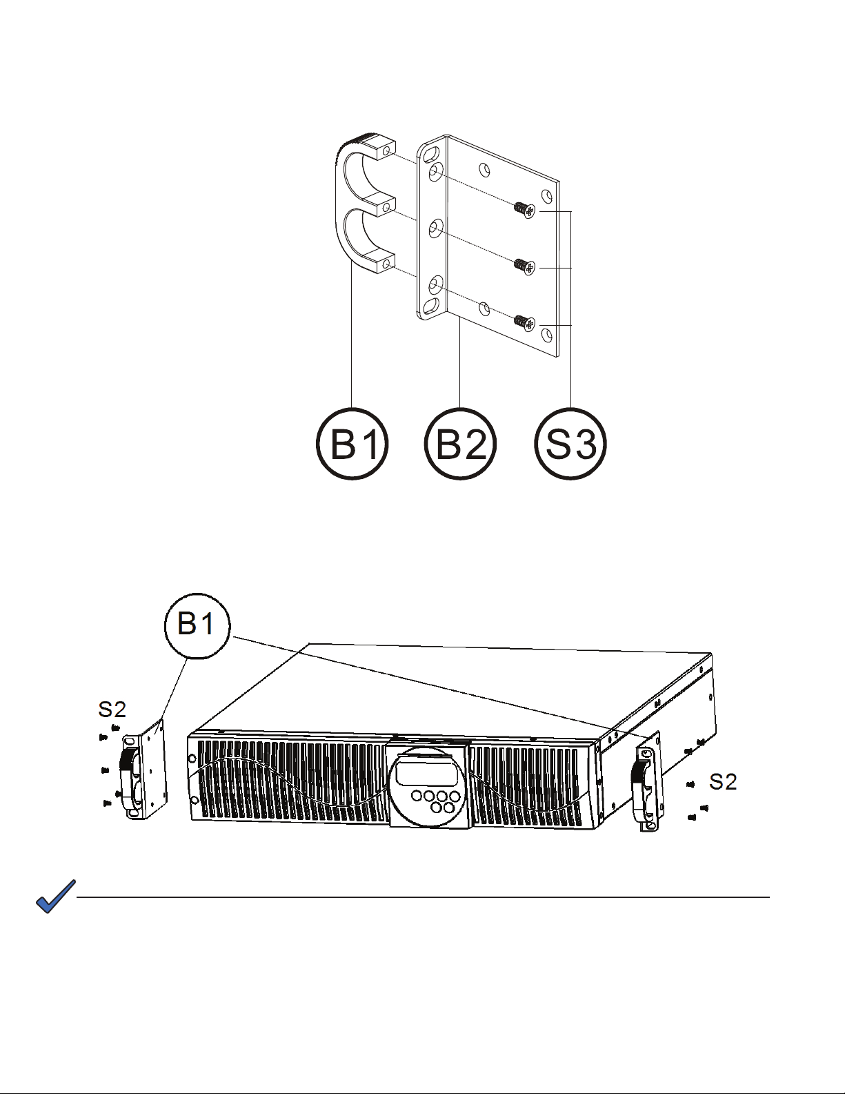
3.5 UPS Position
The UPS can be installed in two different orientations: tower mount (stand alone) or rack mount.
To install the UPS as a tower, see the next section. For rack mount, see Section 3.5.3.
3.5.1 Tower Mount (Stand Alone)
Step 1
NOTE:
See Section 3.6 to rotate the LCD display to match the physical orientation of the unit.
Step 2
S1
A2
A3
S1
8
0170009-J0 Rev B
Page 11
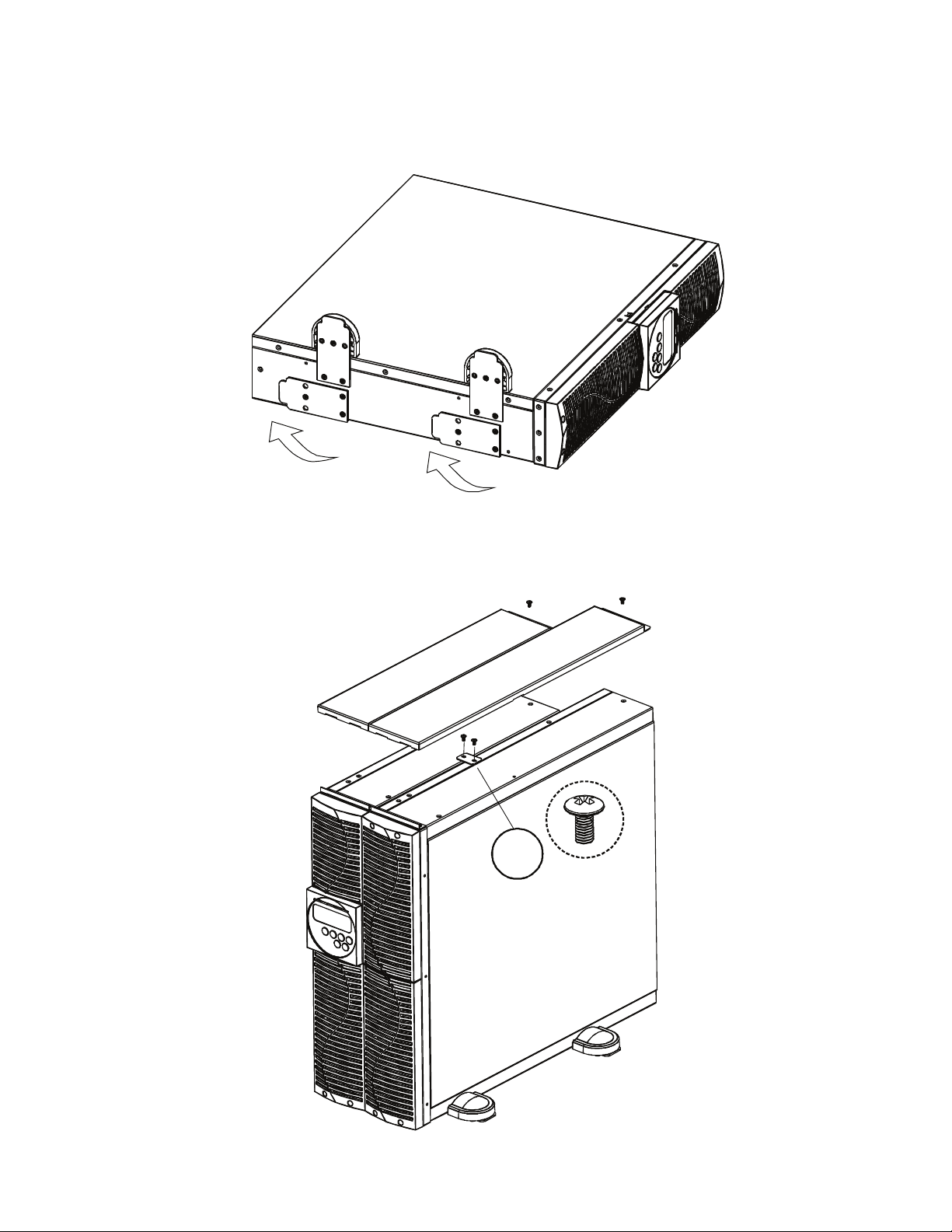
3.5.2 Power Module + Battery Module
Step 1
Step 2
A4
S1
0170009-J0 Rev B
9
Page 12
3.5.3 Rack-Mount Setup
Step 1
Step 2
NOTE:
See Section 3.6 to rotate the LCD display to match the physical orientation of the unit.
10
0170009-J0 Rev B
Page 13
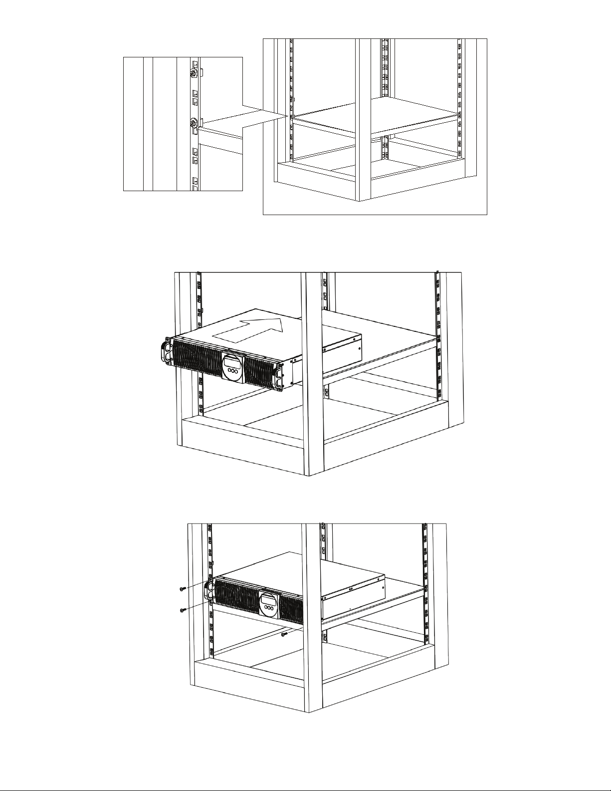
Step 3
Step 4
Step 5
0170009-J0 Rev B
11
Page 14
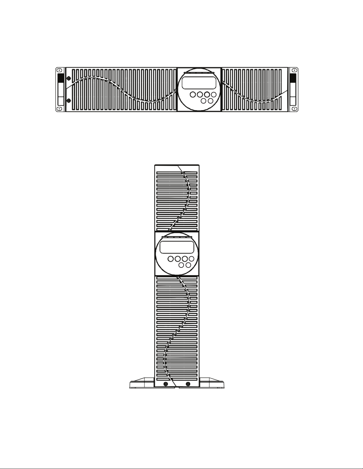
3.6 UPS Front Panel
The front panel can be rotated to accommodate the orientation of the UPS.
To position the display to match the physical orientation of the unit pull the display out, rotate it and then
push it back in.
12
0170009-J0 Rev B
Page 15
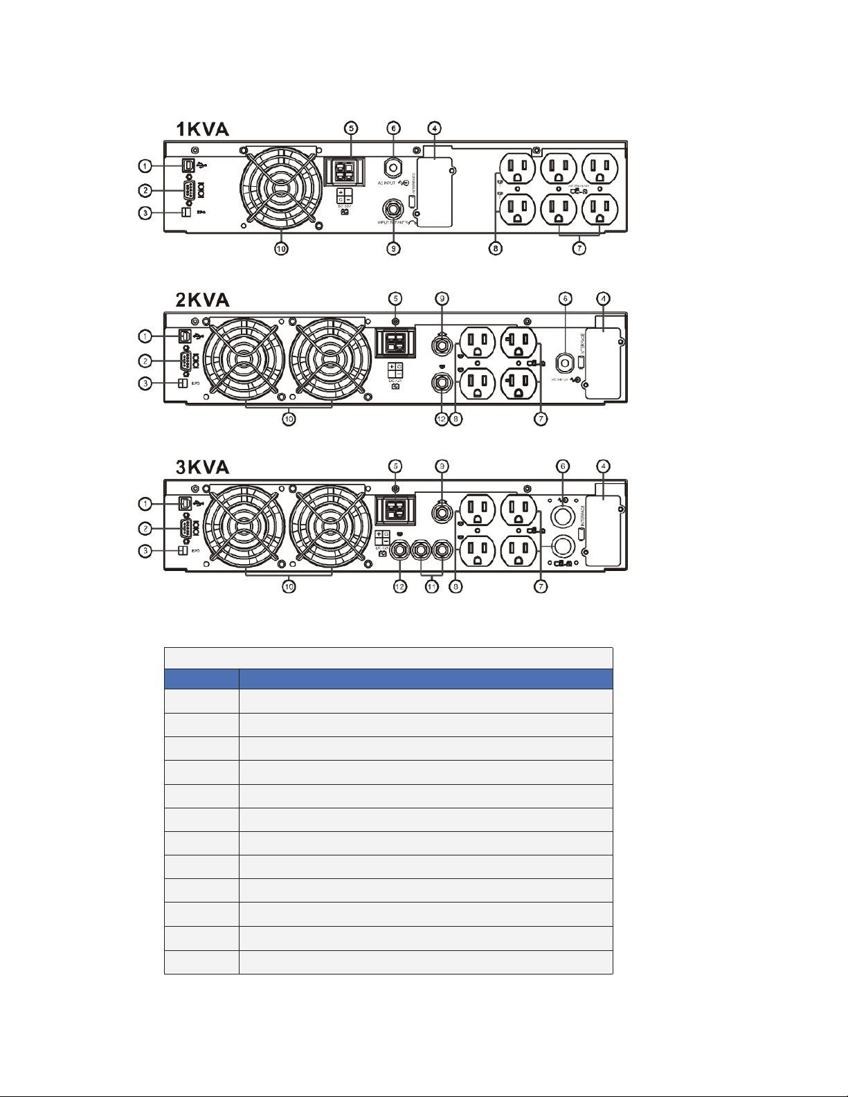
3.7 Rear Panel
3.7.1 120V
Item
1 USB Port
2 RS232 Port
3 Remote Emergency Power Off (REPO)
4 Communication Card Options Slot
5 External Battery Connector
6 AC power connection socket
7 AC Outlets
8 Two programmable outlets
9 Utility Input circuit breaker
10 Cooling fans
11 Output circuit breaker for two outlets
12 Output circuit breaker for two programmable outlets
0170009-J0 Rev B
Table A — 1000/ 2000/ 3000 VA, 120 V
Description
13
Page 16

3.7.2 230V
1KVA
Table B — 1000/ 2000/ 3000 VA, 230 V
Item
1 USB Port
2 RS232 Port
3 Remote Emergency Power Off (REPO)
4 Communication Card Options Slot
6-1 External Battery Connector
6 AC power connection socket
7 AC Outlets
8 Two programmable outlets
9 Utility Input circuit breaker
10 Cooling fans
11 Output circuit breaker for two outlets
12 Output circuit breaker for two programmable outlets
Description
14
0170009-J0 Rev B
Page 17

3.8 Communication Ports
The UPS is equipped with a remote emergency power off (REPO) dry contact input, true RS232 and
USB communication ports to provide communication with bundled UPS monitoring software for remote
monitoring of UPS status via a PC.
Four optional interface cards are available to meet various communication needs (Refer to Section 7):
• DCE (dry contact relay card)
• RS232
• USB
• SNMP/WEB card
The bundled software of the UPS is compatible with many operating systems such as Windows 98, 2000,
ME, NT and XP. For other applications such as Novell, NetWare, Unix, Linux, please contact your local
dealer for suitable software.
All communication ports (including optional cards) can be active simultaneously to monitor the UPS status. However only 1 communication interface can be active at any one time. The interface with the highest priority controls the UPS. The priority of these communication interfaces are as follows from highest to
lowest priority:
• EPO input port
• Optional Interface card
• USB
• RS232
3.8.1 RS232 Port Settings
Set the RS232 interface as follows:
Baud Rate: 2400 bps
Data Length: 8 bits
Stop Bit: 1 bit
Parity: None
3.8.2 USB Port Descriptions
The USB communication protocol definition complies with:
• USB version 1.0, 1.5Mbps
• USB HID Version 1.0.
0170009-J0 Rev B
15
Page 18

4. Installation
4.1 Connecting Utility and Load
The UPS outlets provide battery backup and surge protection for the equipment when the utility voltage is
out of range.
1. Make sure the utility voltage is within the UPS voltage limits.
2. Plug the UPS into a utility power receptacle.
3. Illumination of the green Utility LED
and the amber Bypass LED indicate that utility and
bypass are normal.
4. The LCD screen updates as shown:
5. Plug a computer and monitor into two of the non-programmable outlets.
EPO
DC36 V
G
A
Programmable
outlets
AC OUTPUT
2
B
1
C
CAUTION!
Do not connect a laser printer to the UPS outlets! The printer may overload the UPS and
shut it down.
16
0170009-J0 Rev B
Page 19

6. At the UPS, press and hold the ON switch for approximately 3 seconds until the buzzer sounds
twice.
7. The Initialize screen appears and the UPS automatically runs a self-test sequence.
8. Start-up of the UPS is complete when the Input Voltage screen appears.
NOTE:
At this point the UPS batteries are charging. Plug the UPS into the wall receptacle to
charge the UPS for at least 4 hours after the initial installation.
4.2 Connecting the Computer Interface Port
This section is intended for use of the UPS Setting Tool over a RS-232 connection.
Use the supplied RS-232 cable to connect the interface port on the rear of the UPS to the computer
interface port.
EPO
DC36V
G
ACO UTPUT
2
1
4.3 Operating Modes and Voltage System Configuration
1. Load the supplied UPS Setting Tool CD and install the software.
0170009-J0 Rev B
17
Page 20

2. In the first UPS Setting Tool screen, select your computer's Com Port from the drop down menu.
3. When serial communications are established between the UPS and your computer, the following
screen appears.
18
4. Configure the settings as follows:
System Voltage Selection Select Input Voltage 110V* or 220V*
Voltage Congurations Select UPS Output Voltage
200V/208V/220V/230V/240V or
100V/110V/115V/120V/127V
UPS Modes Select Normal/ CF50** /CF60** Mode
Output Voltage Fine Tuning Output Voltage Regulation from 0 to ~±3%
Bypass Voltage Windows Sensitivity Low Sensitivity High
120V System 90V~130V 97V~130V
230V System 180V~260V 194V~260V
Syn-Frequency Window Select 3Hz/ 1Hz Inverter Freq synchronizing range
Com Port Displays curent PC Com Port
*Select 110V for a 120V input; select 220V for a 230V input
**CF50/ CF60 = Frequency Converter mode 50 to 60Hz or vice versa
5. Click Write to confirm the configuration settings. The UPS beeps twice if the new settings are saved
successfully. Note that the settings do not take effect until you restart the UPS at the end of this
section.
0170009-J0 Rev B
Page 21

Configuring the Programmable Outlet 1/ Programmable Outlet 2
The UPS is equipped with 2 programmable outlets to supply less critical loads. These outlets can be
configured to disconnect the less critical loads during back-up modes or overload conditions to preserve
power to the more critical loads connected to the UPS.
6. Click Programmable outlet setting in the UPS Setting Tool window. The Programmable Outlet
Setting screen appears.
NOTE:
7. Use the following guidelines to set the parameters for the operation of the programmable outlets.
• Outlet Turn On After UPS On – enable the outlet within the time specified when the UPS is powered
on. A value of 0 enables the outlet once the UPS is powered on.
• Outlet Turn Off After AC Failure – disable the outlet within the specified time after utility outage.
• Outlet Turn On After AC Recovered – enable the outlet within the specified time after the utility is
restored.
• Outlet Turn Off When Battery Low - disable the outlet at the specified remaining battery power
capacity(%) during battery mode to disconnect the less critical loads.
• Outlet Turn Off When UPS Overload – disable the outlet during overload condition (bypass mode)
to possibly allow the more critical loads to be continually supplied via Bypass without shut down.
8. Click Setting to save the new parameters. The UPS beeps twice if the new settings are saved
successfully. The setting do not take effect until the system is powered off and on.
Use the On or Off buttons under Manual Control Switch to manually enable or disable the programmable outlets, overriding all previous settings.
Restarting the UPS
9. Press the OFF button for 5 seconds. The buzzer sounds twice and the "off" screen displays.
10. Unplug the power cord form the AC power utility receptacle.
11. After three seconds, reconnect the power cord and restart the computer (See Section "5.2.1 Start Up
In Normal Mode" on page 22.)
12. Plug the UPS into the wall receptacle to charge the UPS for at least 4 hours after the initial installation.
0170009-J0 Rev B
19
Page 22

4.4 REPO Switch
The UPS is equipped with a remote emergency power off (REPO) switch. The user must supply a means
of interfacing with the REPO circuit so that the UPS input feeder breaker can be switched off to interrupt
all sources of power to the UPS and connected equipment. This requirement complies with national and
local wiring codes and regulations.
1 2
1 = REPO+
2 = Ground
Short Pin 1 and Pin 2 to enable the REPO function
20
0170009-J0 Rev B
Page 23

5. Operation
5.1 Front Panel LCD
Symbols
Utility Low
Utility High
Line
Site Wiring/ Ground Fault
Battery Abnormal
UPS Overload
UPS in Service Mode
Bypass
LINE/
LOAD
Er** Error Codes (see Section
OFF UPS Shutoff
FAIL UPS Abnormal Lock
Utility or Bypass Source
6.3)
Figure 1 — Front Panel LCD
Table C — LCD Panel Description
Item
1 LCD display
2 Green Utility LED illuminates to indicate that the Utility input voltage is within the range
3, 4 Green LEDs for Programmable Outlet 1 and Programmable Outlet 2 illuminate to
5 Amber LED illuminates to indicate the Bypass input is normal.
6 Red Fault LED
7 ON/Alarm silence button
8 OFF button
9 Special functions log in/out
10 SCROLL DOWN key: Go to next page
11 SCROLL UP key, Go to previous page or change the setting of the UPS
12 Enter key: to conrm the change of a UPS setting
Manual
Bypass
80Vac~144Vac, or 160Vac~288Vac; the LED ashes to indicate that the Utility input
voltage is within the range 60Vac~79Vac, or 120Vac~159Vac.
indicate power is available at the outlets.
Press and hold the ON key (7) and the SCROLL UP key (11) simultaneously for
~3 seconds to transfer from Inverter to Bypass ( the amber Bypass LED blinks
continuously and the buzzer beeps intermittently)
OR
from Bypass to Inverter, when the UPS is on Line Mode and the Bypass Voltage
Window is Normal.
Description
0170009-J0 Rev B
21
Page 24

5.2 Start Up from the LCD Panel
5.2.1 Start Up In Normal Mode
1. Make sure the utility voltage is within the UPS voltage limits.
2. Connect the UPS to the utility wall receptacle.
3. Illumination of the green Utility LED
bypass are normal.
4. The LCD screen changes from A to B as shown
and the amber Bypass LED indicate that utility and
A B
5. Press and hold the UPS ON switch for approximately 3 seconds until the buzzer sounds twice.
6. Screen C appears and the device automatically runs a self-test sequence.
7. Start up of the UPS is complete when the Input Voltage screen (E) appears. If the self-test fails, the
LCD screen appears as shown in screen D. An error code or error status shows on the screen.
C
D
22
E
Input Voltage
8. The charger starts charging the batteries
9. Leave the UPS plugged into the wall receptacle for at least 4 hours to allow the UPS batteries to
charge fully.
0170009-J0 Rev B
Page 25

5.2.2 Start-up in Battery Mode (Cold Start)
1. Make sure the UPS has been installed complete with batteries.
2. Press and hold the UPS ON button for 3 seconds. The buzzer sounds twice. The LCD displays
screen F.
F
3. Press and hold the UPS ON button for 3 seconds until the LCD display changes from screen F to
screen G.
G
4. The UPS automatically runs a self-test. In about a minute, the UPS supplies power to the output and
the LCD updates to screen H.
If this process fails, the UPS will switch off in 10 seconds.
H
5.2. 3 Check M easured Values and Figures (detected by UPS)
To check the measured values and messages, use the UP and DOWN keys.
When you scroll with the DOWN key, the LCD shows in sequence:
• Screen E (Input Voltage)
• Screen J (Input Frequency)
• Screen K (UPS Output Voltage)
• Screen L (UPS Output Frequency)
• Screen M (UPS Output Load percentage)
• Screen N (UPS Battery Voltage)
• Screen O (UPS inner temperature)
0170009-J0 Rev B
23
Page 26

J
Input frequency
K
L
M
UPS output voltage
UPS output frequency
UPS output load
percentage
24
N
O
UPS battery voltage
UPS inner temperature
0170009-J0 Rev B
Page 27

5.2.4 UPS Default Data and Special Function Execution
To run a self test or check default data, press the Function button to scroll to screen P1.
P1
P2
Press the DOWN button to scroll through the LCD screens and check the UPS settings. The LCD display
shows the following screens in sequence:
• Screen P1 (buzzer)
• Screen Q1 (self test)
• Screen R1 (Bypass Voltage)
• Screen S (Output Frequency Synchronized Window)
• Screen T (Inverter Output Voltage)
• Screen U1 (UPS Operation Mode)
• Screen V (Output Voltage Fine Tuning)
Q1
Q2
R1
R2
Acceptable bypass
input
Acceptable bypass
input
0170009-J0 Rev B
25
Page 28

S
T
U1
U2
Bypass frequency
Inverter output voltage
UPS operation mode:
Online
UPS operation mode:
xed 50HZ output
U3
V
UPS operation mode:
xed 60HZ output
Inverter output calibration
26
0170009-J0 Rev B
Page 29

Press the UP button to execute the following special functions:
• Buzzer ON (screen P1) or buzzer OFF (screen P2)
• Alarm silence for UPS warning
• Self-test ON (screen Q1) or Self-test OFF (screen Q2)
The UPS executes a battery test for 10 seconds. If the battery test is successful, the LCD displays screen
W; otherwise screen D appears with an error message.
W
5.2.5 Changing the UPS Default Settings
1. Make sure the UPS is not switched on, that is, not in Line mode or Backup mode.
2. Simultaneously press and hold the ON button and the DOWN button for ~3 seconds. The buzzer
sounds twice and the LCD display screen updates to screen P1.
The UPS is now in setup mode. Except for the buzzer (screens P1 and P2) and self-test (screens Q1 and
Q2) settings, all default settings can be changed by pressing the UP button.
3. Screens R1 and R2 show the bypass input limits; Acceptable values are 180VAC~ 260VAC for
a 230VAC system, 90VAC~130VAC for 120VAC system or 194VAC~260VAC for 230VAC system,
97VAC~130VAC for 120VAC system.
4. Screen S shows the bypass frequency window of the inverter output, the acceptable setting values
are +/-3Hz and +/-1Hz.
5. Screen T shows the acceptable Inverter Output Voltage: 200V, 208V, 220V, 230V, 240V for 230VAC
system, or 100V, 110V, 115V, 120V and 127V for .
6. Screens U1, U2 and U3 show the operation modes of the UPS: Online, fixed 50Hz output or fixed
60Hz output.
7. Screen V shows the inverter output settings, which can be set to 0%, +1%, -1%, +2%, -2%, +3%, or
-3%.
8. When all the setting have been entered, Screen X appears. Press the ENTER button to save the
X
changes. These changes do not take effect until the UPS is restarted.
9. Switch off the UPS and the utility input breaker.
10. Restart for the changes to take effect.
0170009-J0 Rev B
27
Page 30

5.2.6 UPS Is Off for Unknown Reasons
If a serious abnormal condition occurs, the UPS locks as shown in screen Y.
Y
In most abnormal conditions, the UPS maintains bypass output; however, when it is outside of bypass
window settings, the UPS is locked and the abnormal status is shown as screen Z.
Z
To release the UPS lock, proceed as follows:
1. Check the error messages in Table D in Section 6.3 to troubleshoot the problem. If necessary,
contact your local distributor for service.
2. Press the OFF button for 5 seconds. The buzzer sounds twice.
3. Switch off the utility input breaker.
t
5.2.7 Shut Off
1. Press and hold the OFF button for about 5 seconds: the Inverter output switches off and the UPS
stops supplying power to the loads. The LCD displays screen B.
2. Switch off the utility input breaker.
The UPS is now completely turned off.
5.2.8 Status and Alarm Buzzer
The following table shows the corresponding beeps for each UPS status.
Status Buzzer Beep Descriptions
UPS faulty, Inverter shutdown. All
functions inhibited.
UPS faulty, loads continue to be
supplied via Inverter or Bypass.
Battery mode Single short successive beep with ~1 sec interval
Battery low Very quick and short successive beeps
Conrm/RS232 port receiving 2 short beeps
Service mode OK 1 short beep
Initial start up in self-test mode 2 successive quick & short beeps, repeating per ~2 sec
Long Continuous Beep
Single successive beep with ~ 2 sec interval
interval.
28
0170009-J0 Rev B
Page 31

6. UPS Maintenance
6.1 Battery Replacement Precautions
This UPS is intended for use with a maximum of one extension battery pack. Refer to Section 6.2 for the
installation procedure.
The following precautions apply when replacing batteries in a SERVICE ACCESS AREA:
• Servicing of batteries should be performed or supervised by personnel knowledgeable about
batteries and the required precautions.
• There is a risk of explosion if a battery is replaced by an incorrect type. When replacing batteries,
replace with the same type and number of batteries or battery packs.
CAUTION!
Do not dispose of batteries in a re. The batteries may explode. Dispose of used batteries according to the instructions.
CAUTION!
Do not open or mutilate batteries. Released electrolyte is harmful to the skin and eyes.
It may be toxic.
6.2 Battery Replacement
When the UPS is started up or a self-test is executed, the battery replacement symbol on the LCD panel
may appear because of a weak or dead battery.
1. If the battery replacement symbol on the LCD panel appears, charge the UPS for at least 8 to 10
hours. The symbol should disappear after the self-test function has executed.
2. If the battery replacement symbol stays on after charging, unscrew the battery cover and replace the
battery as shown in the following sections.
CAUTION!
A battery can present a risk of electrical shock and high short circuit current. The following precautions should be observed when working on batteries:
a. Remove watches, rings, or other metal objects.
b. Use tools with insu lated handles.
c. Wear rubber gloves and boots.
d. Do not lay tools or metal parts on top of batteries.
e. Disconnect charging source prior to connecting or disconnec ting battery terminals.
f. Determine if the battery is inad vertently grounded. If inadver tently grounded, remove source from ground.
Contact with any part of a grounded battery can result in electrical shock. The likelihood of such shock can
be reduced if such grounds are removed during installation and maintenance (applicable to equipme nt not
having a ground ed supply circuit).
CAUTION!
The UPS will not provide any output power if the start-up procedure has not completed
properly even though the input power cord is connected to the wall receptacle.
0170009-J0 Rev B
29
Page 32

CAUTION!
The battery is heavy, pull the battery out onto at, stable surface.
CAUTION!
Do not disconnect the batteries while the UPS is in the backup mode.
CAUTION!
Use caution when replacing live batteries.
6.2.1 To Replace the Batteries
STEP 1
STEP 2
STEP 3
1000 VA
30
0170009-J0 Rev B
Page 33

STEP 3
2000/ 3000 VA
Use scissors to cut the tie
wraps.
Disconnect the cables.
Remove the batteries.
6.2.2 Recycling Used Batteries
Contact your local recycling or hazardous waste center for information
on the proper disposal of used batteries.
0170009-J0 Rev B
31
Page 34

6.3 Troubleshooting
When the UPS becomes faulty or malfunctions during operation, check the fault table for possible solutions. Should the problem persists, please contact your local dealer for assistance.
6.3.1 Error Codes
LCD Panel
If an abnormal condition has occurred, the Fault LED illuminates and the buzzer sounds.
Press the LCD OFF key briefly to view the error message.
Do NOT hold the OFF key for over 5 seconds as the unit will shut off.
Code Descriptions
Er05 Battery weak or faulty
Er06 Output short-circuited
Er07 REPO mode
Er11 UPS over-temperature
Er12 Inverter overload
Er14 Fans out of order
Er18 EEPROM's data error
Er24 Utility Low (<85/170V) and Battery Disconnected
Er28 Bypass overload
Er31 EEPROM data does not conform to the Jumper Setting
Table D — Error Codes
32
0170009-J0 Rev B
Page 35

Situation Error Indication Solution
UPS Fault
LED
Table E — Troubleshooting Table
Er05 Check battery connection.
Refer to Table D for error
codes).
Measure Battery voltage to ensure batteries are
charged or healthy. Recharge batteries for 4 hours
if necessary.
Simulate Utility outage to verify if UPS is able to
provide DC back-up.
Otherwise consult your local dealer right away.
Overload Disconnect some non critical loads from the UPS
Er11 (UPS over
Temperature)
Site wiring/
Ground fault
Er14 (Fans out
of order)
output until overload ceases.
Check for short circuit between cables due to
broken cable insulator. Replace the cables in
necessary.
Remove any objects obstructing the ventilation
louvers.
Verify if the cooling fans are working properly.
Contact your local dealer to replace the fans if
necessary.
Verify if the L and N phase of the Utility AC source
is incorrectly wired or if the Ground-Neutral Voltage
exceeds the limits
Verify ventilating fans are functioning.
UPS fails to provide
battery backup or its back
up time is shorter than its
intended performance.
UPS is normal but no
Output to load
The UPS switches to
battery mode then back
to Utility mode, when
a connected device is
turned on. Or,
The UPS switches back
and forth between battery
and utility.
Other error
codes
Do not attempt to replace the fans by yourself.
Contact your local dealer for replacement
Consult your local dealer for assistance.
If the backup time remains unsatisfactory after 4
hours of charging, contact your local dealer for
battery replacement.
Check that all power cords are properly connected.
If problem persists, consult your local dealer for
technical assistance.
If a power bar is connected to the UPS, Do not use
the power bar.
Check for damage to the utility wall receptacle,
cable, or plug. replace if necessary.
0170009-J0 Rev B
33
Page 36

Table E — Troubleshooting Table
Situation Error Indication Solution
Strange noise and smell Immediately shut down the whole System.
Disconnect the power from the UPS and call for
service.
UPS is unable to provide
backup power source
Check that the battery connectors are fully
engaged.
Allow the battery to recharge if the battery is weak.
If problem persists after recharging, replace the
battery.
If problem persists consult your local dealer for
technical assistance.
34
0170009-J0 Rev B
Page 37

7. Optional Communication Cards
All of the following cards can be installed in the optional slot:
• R2E (2nd RS-232 ) card
• USB card
• DCE (Dry Contact) card
• SNMP cards
7.1 R2E (2nd RS-232 ) card
CN1 is for RS232 DB9.
For communication protocol, refer to 3.8 on page 15.
7.2 USB card
CN1 is for USB.
7.3 DCE (Dry Contact) card
The pin assignments of 10-Pin Terminal
1 2 3 4 5 6 7 8 9 10
Pin Function
1 UPS on Bypass mode (Bypass)
2 Utility Normal (Normally close contact)
3 Utility Normal (Normally open contact)
4 Inverter On
5 Battery Low
6 Battery Bad or abnormal
7 UPS Alarm
8 Common
9 Shutdown UPS positive(+) signal
10 Shutdown UPS negative(-) signal
The shutdown function is activated, after +6 to +25 VDC is put between pin 9 and pin 10 for 5 seconds.
The capacity of each relay contact is 40VDC/25mA.
Flexible signal output for NC (normally closed) or NO (normally open) contact by shorting pin 1 to 2, or
pin 2 to 3 from JP1-5.
The shutdown function is enabled 1 minute after blackout occurs if pin 1 to 2 of both CN1 and CN6 are
shorted. Or, the shutdown function can only be enabled by pin9-10 of CN3 if pin2-3 of both CN1 and
CN6 are shorted.
7.4 SNMP Cards
7.4.1 SNMP/WEB card
For installation, refer to the user’s manual that comes with the card.
0170009-J0 Rev B
35
Page 38

8. Specifications
Table F — Specications
Model AIDCO 1kVA AIDCO 2kVA AIDCO 3kVA
VA rating
Apparent Output Power 1000VA 2000VA 3000VA
Active Output Power PF=0.8 800Watts 1600Watts 2400Watts
Power Factor 0.8
Topology Double conversion On-Line
Type Rack/Tower
Agency Approvals
Input
Voltage Window
Low Line
Transfer
Voltage
Range
Frequency 50/60 Hz auto-select, ± 5Hz
Phase Single phase with ground
Power Factor >0.99 at full rated linear load
Transfer time 0 ms typical
Low Line
Comeback
High Line
Transfer
High Line
Comeback
115V 60/70/80 - 144VAC
230V 120/140/160 - 288VAC
Based on load percentage (0~33/33~66/66~100%)
115V 60/70/80VAC
230V 120/140/160VAC
115V 85VAC
230V 170VAC
115V 144VAC
230V 288VAC
115V 139VAC
230V 278VAC
115V Models: UL, cUL, FCC
230V Models: CE
Waveform
Surge protection
36
115V ≤ 5mA
230V ≤ 3.5mA
115V 400 joules
230V 300 joules
0170009-J0 Rev B
Page 39

Output
Voltage
Voltage Regulation ≤ ± 1% until low battery warning
Frequency(Synchronized
Range)
Output INV mode
Efciency
Model number AIDCO 1 kVA AIDCO 2 kVA AIDCO 3 kVA
Type 12V/7.2Ah 12V/7.2Ah 12V/9Ah
Number of Batteries 3 6 6
Frequency(Battery Mode) ±0.1% (0.05~0.06Hz) unless synchronized to line
Current
Crest Factor
Harmonic Distortion
Transient Response (ms) ≤ 60ms/±5%
Waveform Pure sine wave
To AC Mode (Full load) 85% 85% 88%
To Battery Mode (Full load) 83% 83% 85%
115V 115V, adjustable to 100/110/115/120/127
230V 230V, adjustable to 200/208/220/230/240
3Hz or 1Hz (setting by software)
PF=0.8 2.7:1
1KVA,2KVA, 3KVA ≤ 3% THD(Linear Load)
1.5KVA ≤ 4% THD(Linear Load)
≤ 7% THD(Non-Linear Load)
Battery Parameters
Backup Time (Full Load) PF=0.8 >5min. >5min. >4min.
Recharging Time 4 Hours to 90%
Charging Current (Max.) 1.8A 2.16A 2.7A
Charging Voltage 41.0Vdc ±0.5V 82.0VDC ±0.5V 82.0VDC ±0.5V
Hot Swappable Battery Yes
Internal battery Yes
DC leakage current
Battery type Sealed, non-spill, maintenance-free, lead acid
AC to DC Zero
Inverter to Bypass 2.5ms (Typical) Zero
DC Start Yes
Self Diagnostics By button on the panel or Software Control
LED
≤ 30uA (±10uA) with no AC applied and the unit in the off
position
Transfer Time
Front Panel
Load Level/Battery Level/ Battery Mode/ Normal Mode/
Bypass Mode/ Self-Test/ Weak/Bad Battery/Site Wiring Fault/
Fault/ Overload/Programmable Outlet1//Programmable
Outlet2
Key ON Button/ OFF Button/ (Test/Alarm Reset Button)
0170009-J0 Rev B
37
Page 40

Overload
Protection
(AC Mode )
<105% continuous
>106%~120% for 30 sec transfer to bypass
>121%~150% for 10 sec transfer to bypass
>150% for immediate transfer to bypass
Buzzer continuously alarms.
(Battery Mode)
<105% continuous
>106%~120% for 30 sec shut down
>121%~150% for 10 sec shut down
>150% for immediate shut down
Buzzer continuously alarms.
(Bypass Mode)
<105% continuous
>106%~120% for 250 sec shut down
>121%~130% for 125 sec shut down
>131%~135% for 50 sec shut down
>136%~145% for 20 sec shut down
>146%~148% for 5 sec shut down
>149%~157% for 2 sec shut down
>158%~176% for 1 sec shut down
>177%~187% for 0.32 sec shut down
>188% for 0.16 sec shut down
Buzzer continuously alarms.
Bypass mode : Input Fuse/Input Breaker
Short Circuit
Battery ABDM
EPO UPS shuts down immediately
Normal Mode Transfer to Bypass Mode
Over Temperature
Battery Mode UPS shuts down immediately
Battery Mode Sounding once every 1.5 sec
Low Battery Sounding once every 0.2 sec
Overload Sounding once every 3 sec
Fault Continuously Sounding (or Sounding once every 3 second)
Operating Temperature +32°F to + 104°C (0°C to + 40°C)
Storage Temperature +5°F to + 104°F (-15°C to + 40°C)
Relative Humidity 0% to 90%, non-condensing
Noise Level <50dBA
Normal Mode: Output Breaker/Electronic Circuit
Battery Mode: Output Breaker/Electronic Circuit
Audible Alarm
Environmental
38
0170009-J0 Rev B
Page 41

Interface
Interface Type 1 *USB port+ 1 *RS-232 port
SNMP(option) Power management from SNMP manager and Web browser
Compatible platforms Windows 2000/XP/7 Novell NetWare, Linux, etc.
Standards and Certication
Safety IEC/EN 62040-1-1,IEC 60950-1
Performance IEC/EN 62040-3
EMC
Markings CE,UL, cUL, FCC
IEC/EN62040-2 Class A, FCC Part 15 Subpart B Class A,
IEC/EN55011, CISPR11, IEC61000-4-2/-3/-4/-5, IEC61000-22, IEC61000-3-2/-3
0170009-J0 Rev B
39
Page 42

9. Warranty and Service Information
Technical Support
Free Technical Support 24/7/365 is part of the Alpha customer satisfaction commitment. The phone numbers below can also be used to access a wide range of service solutions both at your premise and at the
Alpha facility nearest you.
In Canada and the USA, call toll fre e 1-888-462-7487 24 hours a day, seven days a week.
Customers outside Canada and th e USA, call +1-604-436-5547.
Warranty
Alpha Technologies Ltd. warrants its equipment to be free of manufacturing defects in material and workmanship, for a period of 36 months from the date of shipment from the factory. The warranty provides for
repairing, replacing or issuing credit (at Alpha’s discretion) for equipment shipped by it and returned by
the customer to the factory or other authorized location during the warranty period.
There are limitations to this warranty coverage. The warranty does not provide to the customer or other
parties any remedies other than the above. It does not provide coverage for any loss of profits, loss of
use, costs for removal or installation of defective equipment, damages or consequential damages based
upon equipment failure during or after the warranty period. No other obligations are expressed or implied.
Warranty also does not cover damage or equipment failure due to cause(s) external to the unit including,
but not limited to, environmental conditions, water damage, power surges or any other external influence.
The customer is responsible for all shipping and handling charges. Where products are covered under
warranty Alpha will pay the cost of shipping the repaired or replacement unit back to the customer.
Battery Warranty
Battery warranty provided by Alpha is a three year full replacement warranty with a pro-rated warranty
for the following two years. Pro rated warranty provides a credit applicable toward the purchase of new
batteries from Alpha. The credit is calculated as the purchase price multiplied by the percentage of the
battery life that was not available (in months). Battery warranty coverage is lost where the battery charge
is not maintained for 6 months. Contact your Alpha sales representative or the Technical Support team at
the above number to understand your entitlements under Battery Warranty.
Extended Warranty
The terms of warranty can be extended in time by purchase of an Extended Warranty. Warranty extensions are available on a per year basis and can be purchased during the initial warranty period.
Return of Material
Please contact Technical Support at the number above to obtain a Service Repair Order (or Return Material Authorization) number BEFORE sending material back. This will ensure that your service needs are
handled promptly and efficiently.
On Site Services and Service Plans
A wide range of services are available at your location including installation, commissioning, preventative maintenance, remedial maintenance, battery replacement, battery delivery, etc. Preventative maintenance is recommended for Alpha products at least once per year. Customers can arrange to have these
services provided automatically with one annual payment.
Service Centers
For a list of service centers, please visit:
http://www.alpha.ca/web2/about-alpha/service-centers.html
40
0170009-J0 Rev B
Page 43

Appendix A
PFC
AC/DC
INVERTER
DC/AC
BOOST
DC/DC
CHARGER
BATTERY
Control
Circuit
A-1 Theory of Operations
The UPS System Block Diagram below illustrates the true on-line double conversion architecture of the
UPS system.
The major modules consist of the following:
• AC to DC power converter (rectifier) with a Power Factor Correction
• DC to AC power high frequency inverter
• Isolated intelligent battery charger
• Bank of stationary maintenance-free batteries
• DC to DC converter
• Static bypass loop
• Input and output EMI filters
The following table summarizes the UPS operating modes during various utility AC power conditions:
Utility Conditions
Utility normal
Utility abnormal
(under or over
voltage) or absent
Utility abnormal or
absent, battery low
voltage
The following sections describe the operation of the UPS under different conditions.
0170009-J0 Rev B
UPS Operating Modes
Rectier converts AC to DC. Battery charges. Inverter
converts DC to AC and supplies the loads with clean, stable
power.
Rectier and charger stop operating. Battery discharges
via DC-DC boost circuit and supplies the inverter. Loads
continue to receive supply from the inverter. Buzzer beeps.
UPS on battery mode.
Rectier and charger stop operating. Battery discharges via
the DC-DC boost circuit and supplies the inverter. Buzzer
sounds short and frequent beeps, indicating that the battery
power is low and the inverter will stop working at any
moment.
LED Display
indications
, , LEDs
illuminated
green
LED
extinguished
LED extinguished
LED illuminated
LOW
symbol on LCD
41
Page 44

A-2 Utility is Normal
When the utility voltage is normal, the AC power is rectified to DC power, which is then fed into the inverter. The charger is switched to charge the batteries. The inverter transforms the DC power to clean AC
power that supplies the loads. The , ,and LEDs are illuminated.
A-3 Utility Power is Abnormal/Absent
The working principle of the UPS when the utility power is abnormal is illustrated below:When the utility
power is abnormal (under voltage, over voltage or absent), the UPS converts battery power to AC power
through the DC-DC and DC-AC inverter. It also disables the AC-DC and charger sections. This happens
instantaneously as the abnormality is detected.
1. When utility power returns to normal, the UPS switches to normal mode as explained in the previous
section.
2. During a utility outage, the figure above illustrated the operation of the UPS. When the batteries are
depleted, the buzzer beeps continuously until the unit is shutdown. The UPS low battery protection
shuts off the output after a preset threshold to avoid over-draining the batteries. The
low)& (battery abnormal) symbols appear on the LCD until the UPS is completely shut off. The
UPS re-starts automatically when the utility is restored.
A-4 Overload Condition
1. Most electronic and IT equipment draw an inrush current when turned on. The amplitude and
duration of the inrush current varies depending on the equipment. Some inrush currents can be
as high as six times the rated capacity while some equipment produce negligible inrush currents.
To prevent severe inrush current damage to the inverter, the UPS is equipped with an electronic
overload protection feature. If the UPS load is between 105 and 120% of its capacity, it switches to
the bypass mode after 30 seconds to protect the inverter. If the overload condition is removed, the
UPS switches back to inverter mode. If the UPS load is more than 150% of its capacity, the inverter
shuts down immediately.
LOW
(battery
2. The UPS bypass loop is also equipped with overload protection. Its overload capacity is illustrated by
the graphs and table below.
42
0170009-J0 Rev B
Page 45

A-5 Inverter Failure
If there is a short circuit in the output circuit when the power is supplied from the inverter, the UPS shuts
down the inverter to shut off power to the loads. The fail LED illuminates and the buzzer beeps continuously. The UPS does not switch on automatically after the short circuit condition disappears. The UPS
must be re-started manually. Refer to Section 5.2.1, Start Up in Normal AC Mode.
A-6 Inverter/Internal Over temperature
The UPS switches to the bypass mode if the UPS experiences an internal over-temperature when the
utility voltage is normal. The UPS switches back to the inverter mode when the over-temperature disappears. If an over temperature occurs when the utility voltage is outside the UPS design limits, the buzzer
beeps continuously and the Fault LED illuminates. The UPS shuts off the power to the loads.
A-7 Inverter Over
An Inverter Over condition means that the current and inverter output voltages are outside the design
limits.
If the UPS inverter delivers an over-current and out-of-tolerance voltage to its outlets, the UPS is out of
order. The UPS switches to the bypass mode if the utility voltage is normal. The Utility LED, Bypass
LED, and Fault LED illuminate.
If these two fault conditions occur when the utility voltage is outside the UPS design limits, the UPS shuts
off the power to the loads and the Fault LED illuminates.
0170009-J0 Rev B
43
Page 46

Page 47

Page 48

Alpha Technologies Ltd.
7700 Riverfront Gate
Burnaby, BC V5J 5M4
Canada
Tel: +1 604 436 5900
Fax: +1 604 436 1233
Toll Free: +1 800 667 8743
Alpha Technologies Inc.
3767 Alpha Way
Bellingham, WA 98226
United States
Tel: +1 360 647 2360
Fax: +1 360 671 4936
Alpha Industrial Power Inc.
1075 Satellite Blvd NW,
Suite 400
Suwanee, GA 30024
United States
Tel: +1 678 475 3995
Fax: +1 678 584 9259
Alpha Energy
1628 W Williams Drive
Phoenix, AZ 85027
United States
Tel: +1 602 997 1007
Fax: +1 623 249 7833
Alpha Technologies Europe Ltd.
Twyford House Thorley
Bishop’s Stortford
Hertfordshire, CM22 7PA
United Kingdom
Tel: +44 1279 501110
Fax: +44 1279 659870
Alpha Technologies
Unit 504, 5/F,
Fourseas Building
No 208-212 Nathan Road
Kowloon, Hong Kong
Tel: +852 2736 8663
Fax: +852 2199 7988
Alpha Technologies GmbH
Hansastrasse 8
D-91126
Schwabach, Germany
Tel: +49 9122 79889 0
Fax: +49 9122 79889 21
Alphatec Ltd.
339 St. Andrews St.
Suite 101 Andrea Chambers
P.O. Box 56468
3307 Limassol, Cyprus
Tel: +357 25 375 675
Fax: +357 25 359 595
Alpha Brasil Serviços
e Comércio Ltda.
Rua Manuel Augusto de Alvarenga, 155
São Paulo, SP - Brasil
Tel: +55 11 2476 0150
Fax: +55 11 2476 0150
Technologies Argus
First de Mexico
Anatole France Num. 17
Colonia Polanco
11560, México D.F.
Tel: +52 55 5280 6990
Alpha TEK ooo
Khokhlovskiy Pereulok 16
Stroenie 1, Office 403
Moscow, 109028
Russia
Tel: +7 495 916 1854
Fax: +7 495 916 1349
Alphatec Baltic
S. Konarskio Street 49-201
Vilnius, LT-03123
Lithuania
Tel: +370 5 210 5291
Fax: +370 5 210 5292
Visit us at www.alpha.ca
Due to continuing product development, Alpha Technologies reserves the right to change specifications without notice.
Copyright © 2011 Alpha Technologies. All Rights Reserved. Alpha® is a registered trademark of Alpha Technologies.
 Loading...