


Operating Manual
SG1 Vulcanizer Switchgear Control Box
ORDER NUMBER: BAT-SG1-001
Revised - April 2014
This manual was prepared to present the correct methods
and procedures of operating and maintaining your
ALMEX SG1 SWITCHGEAR CONTROL BOX
At the time of writing this manual, the instructions were up to date.
However, some of the information or appearance of the component parts may vary slightly from the SG1 delivered to you.
READ THIS MANUAL CAREFULLY BEFORE OPERATING YOUR SWITCHGEAR CONTROL BOX
49900-038

Table of Contents
1. SAFETY 3
1.1. Safety Symbols 3
1.2. Definition of Pictograms 3
1.2.1. Caution 3
1.2.2. Electrical Hazard 3
1.2.3. Burning Hazard 3
1.3. Work Area Safety 3
1.3.1. Keep Work Area Clean 3
1.3.2. Keep Visitors Away 3
1.4. Personal Safety 3
1.4.1. Stay Alert 3
1.4.2. Never Alter or Remove Safety Devices 4
1.4.3. Use Safety Equipment 4
1.5. Service and Maintenance Safety 4
1.5.1. Use Authorized Service Only 4
1.5.2. Use Only Authorized Replacement Parts 4
1.5.3. Never Use a Defective or
Abnormally Operating SG1 4
1.6. Limitation of Use 4
2. PRODUCT OVERVIEW 4
3. HARDWARE OVERVIEW 5
3.1. WiFi Antenna 6
3.2. Platen Set 1 and Platen Set 2 Switches 6
3.3. Auxiliary Switch 6
3.4. USB Cable Receptacle 6
3.5. Reset Button 6
3.6. Warning Alarm 6
3.7. Tablet Power Receptacle 6
3.8. Thermocouple Receptacles 6
3.9. Temperature Set Point Indicator 6
3.10. Platen Set 1 and 2 Temperature
Indicators 6
3.11. Platen ON LED 6
3.12. Set Point Reached LED 6
3.13. LCD User Interface 7
3.14. Wireless Pressure Sensor Antenna 7
3.15. Network Master Indicator 7
3.16. Left and Right Auxiliary Receptacles 7
3.17. Upper and Lower Platen Receptacle
(Set 1 & 2) 7
3.18. SG1 Networking Receptacle 7
3.19. Power Main Input Receptacle 7
3.20. Wireless Pressure Sensors and
Schrader Valves 7
3.21. Spare Fuses 7
3.22. Power Cable 7
3.23. Front Panel Dust Cover 7
3.24. Thermocouple Cables 7
3.25. Networking Cables 8
4. SETTINGS 8
4.1. Network Settings 8
4.2. Control Settings 8
4.2.1. Auto-Tuning Support 8
4.2.2. Temperature Offset 8
4.3. Alarm Settings 8
4.3.1. Maximum Pressure 8
4.3.2. Temperature Range 8
4.3.3. Minimum Current 9
4.3.4. Platen Disconnection 9
4.4. Interface Settings 9
4.4.1. Temperature Units 9
4.4.2. Language 9
4.4.3. Sounds 9
5. SENSOR READINGS 9
5.1. Pressure Readings 9
5.2. Pressure Sensor Registration Procedure 9
5.3. Current Readings 9
5.4. Thermocouple Readings 10
6. PREPARATION 10
6.1. Unpacking 10
6.2. Connection Assembly 10
7. OPERATION 11
7.1. Heating the Vulcanizer 11
7.1.1 Automatic Heating 11
7.1.2. Manual Heating 11
7.1.3. Cooling 11
7.1.4. Splice Resume 11
8. OPERATION WITH MULTIPLE SG1s 11
8.1. Description 11
8.2. Preparation 12
9. MAINTENANCE AND REPAIR 13
9.1. Replacing Fuses 13
9.1.1 Opening the SG1 13
9.1.2 Fuse Replacement 14
9.1.3. Closing the SG1 14
10. TROUBLESHOOTING 15
10.1 No Reading on Platen Set 1 and/or
Platen Set 2 Temperature Indicators 15
10.1.1 Power Supply or Cable is Faulty. 15
10.1.2. Control Circuit Fuse has Opened 15
10.2 “Err” Displayed on Platen Set 1 and/or
Platen Set 2 Temperature Indicators 15
10.2.1. Platen not Connected 15
10.2.2. Loose Connection in Cable or
Platen Connector 15
10.2.3. RTD Temperature Sensor is Faulty 15
10.3. Platens Not Heating 15
10.3.1. Power Supply or Cable is Faulty 15
10.3.2. Platen Switch Off 15
10.3.3. Temperature Set Improperly 15
10.3.4. No Continuity Between
SG1 and Platen 15
10.3.5. Loose Connection in the
SG1 Control Panel 15
10.3.6. Faulty RTD Temperature Sensor
in Platen 15
10.3.7. Faulty Heating Element in Platen 15
10.3.8. Faulty Contactor in SG1 Control Panel 15
10.3.9. Loose Connection in Cable
or Platen Connector 15
10.3.10. Faulty Temperature Controller
in SG1 Control Panel 15
10.4. Vulcanizer Overheating 16
10.4.1. Temperature Set Improperly 16
10.4.2. Faulty Contactor in SG1 Control Panel 16
10.4.3. Faulty RTD Temperature Sensor
in Platen 16
10.4.4. Faulty Temperature Controller in
in SG1 Control Panel 16
10.5. Unit Fails to Create SG1 Network 16
10.5.1. Improper Network Configuration 16
10.5.2. Faulty Network Connectors 16
10.5.3. Faulty Communication on
SG1 Motherboard 16
11. SG1 PARTS LIST 17
12. SERVICE 18
12.1. Emergency Service 18
12.2. Return of Goods Authorization 18
12.3. Guarantee 18
13. SCHEMATIC DIAGRAMS 18
Revised - April 2014 49900-038
22
Shaw Almex Industries | 1.800.461.4351 | www.almex.com

SHAW ALMEX INDUSTRIES LIMITED
323 Glover Road, Stoney Creek, ON Canada L8E 5M2
Phone: 905-643-7750
toll free 800-418-2400 (Canada and US only)
Fax: 905-643-7788
Email: sail@almex.com
Web: www.almex.com
1. Safety
Your ALMEX SG1 Switchgear Box has been designed to provide
safe, efficient, trouble-free service for many years. Component
design and material selection have been carefully considered
to ensure operator safety. Our manufacturing procedures pro
vide a consistent, high-quality product.
The material presented in this operating manual has been com
piled to provide personnel with a complete understanding of
correct SG1 operating procedures.
PLEASE READ CAREFULLY
The following safety precautions should be read carefully and
understood thoroughly before you set-up or operate your SG1.
Failure to follow these precautions may result in personal injury
and/or equipment damage. All personnel should be trained in
the proper operation of the SG1.
Risks associated with operating the SG1 are identified through
out this manual with safety symbols.
1.1 SAFETY SYMBOLS
These international safety symbols are used to identify and
call attention to specific safety matters. The risks associated with operating the switchgear control are identified
throughout this manual with these symbols.
CAUTION
ELECTRICAL
HAZARD
BURNING
HAZARD
-
-
-
1.2 DEFINITION OF PICTOGRAMS
1.2.1. CAUTION
Indicate[s] a hazardous situation which, if not avoided,
could result in minor or moderate injury. CAUTION
[signs] without a safety alert symbol may be used to alert
against unsafe practices that can result in property dam
age only.
1.2.2. ELECTRICAL HAZARD
1. A qualified electrician should perform all maintenance
of the electrical components of the switchgear control
box. Service or maintenance performed by unqualified
personnel could result in risk of injury and will void war
ranty.
2. Electrical components contain live circuits. Do not
open or service any of the electrical equipment
without disconnecting the main power supply.
3. Incorrect voltage and phase may result in com
ponent damage and create a fire hazard.
4. Equipment power supplies must be properly
grounded or a severe shocking hazard may result.
5. Avoid using equipment in wet surroundings
or a severe shocking hazard may result.
6. If any cables or connectors are damaged, they must
be replaced or a fire and shock hazard may result.
1.2.3. BURNING HAZARD
There is not a burning hazard with the switchgear control
itself; however, improper use or component failure could
result in the vulcanizer overheating.
1.3 WORK AREA SAFETY
1.3.1 KEEP WORK AREA CLEAN
Cluttered areas and benches invite injuries.
1.3.2 KEEP VISITORS AWAY
Do not let visitors contact power cables or platen cables.
All visitors should be kept away from work area.
1.4 PERSONAL SAFETY
1.4.1 STAY ALERT
Watch what you are doing and use caution when operating
the SG1. A moment of inattention while operating power
equipment may result in serious personal injury or death.
-
-
-
Shaw Almex Industries | 1.800.461.4351 | www.almex.com
49900-038Revised - April 2014
3

1. Safety CONTINUED
2. Product Overview
1.4.2 NEVER ALTER OR REMOVE SAFETY DEVICES
1.4.3 USE SAFETY EQUIPMENT
Always wear eye protection. Dust mask, hard hat or hearing
protection must be used for appropriate conditions. Nonskid, steel-toe safety shoes are required for safe operation,
due to the SG1’s weight.
1.5 SERVICE AND MAINTENANCE SAFETY
1.5.1 USE AUTHORIZED SERVICE ONLY
Service must be performed only by qualified personnel.
Service or maintenance performed by unqualified
personnel could result in risk of injury and will void warranty.
Contact your Almex representative to determine if service
is required by an Almex technician.
1.5.2 USE ONLY AUTHORIZED REPLACEMENT PARTS
When servicing SG1, use only identical replacement
parts. The use of unauthorized parts or failure to follow
“Maintenance Instructions” may result in electric shock or
injury.
1.5.3 NEVER USE A DEFECTIVE OR ABNORMALLY
OPERATING SG1
If the SG1 appears to be operating unusually, making a
strange noise or appears defective in any way, stop using
it immediately and make arrangements to have it repaired
by an Almex Technician.
1.6 LIMITATION OF USE
This equipment has been designed to control the temperature
of an ALMEX conveyor belt vulcanizer. The SG1 Switchgear
Control Box operates within a range of -30ºC to 45ºC (-22ºF to
113ºF). An ALMEX Switchgear Control Box must be used with
a ALMEX vulcanizer. The vulcanizer should never be allowed
to operate while unattended. Only use the SG1 for what it
is designed for, other use is not allowed without the written
permission of Shaw Almex.
The Almex SG1 Switchgear Control Box is the most advanced
vulcanizing control system in the world. It incorporates control of four
platens and has input for eight thermocouple leads so that redundancy
in temperature monitoring and recording is accomplished. It also
utilizes wireless sensors to record pressure bag readings.
The SG1 follows a user specified splice recipe that maintains a
dwell and cure temperature at a specified dwell time and cure
time. Using an advanced control method called PID, the SG1
reduces the effect of temperature overshoot by turning the platens
on and off in pulses. The splice can be started and stopped using
an ALMEXPAD or using the LCD display on the front panel of
the SG1.
Once begun, a splice continues automatically and does not
require intervention until the cure is finished and cooling
commences. The stages of the splicing process are displayed. (See
FIGURE 1) When no splice is specified and no heating or cooling is
taking place the splice-info screen will read “status: ready”.
When splice parameters are input and a splice starts, the device
starts in the “To Dwell” phase. When all connected platens reach the
dwell temperature, the platen begins the “At Dwell” phase. In this
phase of operation the SG1 maintains the set temperature for a set
time. Remaining dwell time can be viewed on the LCD display in the
“Splice Info” menu or on the ALMEXPAD Splice Monitor screen.
When the “At Dwell” phase is completed, the SG1 enters the
“To Cure” phase and heats up until all platens rise to meet the specified cure temperature called the “At Cure” phase. In this phase the
SG1 maintains the set temperature for a set time. (See FIGURE 1)
Once the Cure time elapses, the SG1 enters a “Cooling” state. At
this point, operators may pump coolant into the platens to speed
up the cooling phase with an ALMEX pressure pump. (See FIGURE
2) After all platens cool below the Cooling temperature, the splice
is complete.
NOTE: At any time during the operational phase the splice can
be emergency stopped by going to the “Splice Info” menu and
selecting the “Stop Splice” option.
FIGURE 1 - SPLICE GRAPH
Revised - April 2014 49900-038
4
Shaw Almex Industries | 1.800.461.4351 | www.almex.com
FIGURE 2 - PRESSURE PUMP

3. Hardware Overview
FIGURE 3 -
SG1 FUNCTIONAL
DIAGRAM
Revised - April 2014
FIGURE 4 - SG1 FUNCTIONAL DIAGRAM
Shaw Almex Industries | 1.800.461.4351 | www.almex.com
49900-038
5

3. Hardware Overview
SG1 FRONT PANEL
3.1. WIFI ANTENNA
Allows the SG1 Switchgear Box to connect wirelessly to
ALMEXPAD Senior and exchange data.
3.2. PLATEN SET 1 AND PLATEN SET 2 SWITCHES
The main heating controls are
located on the left side of the SG1
front panel.
Each control, can be
set in the AUTO, OFF, or
MANUAL position. In AUTO mode,
the SG1 controls the splice
according to the splice parameters
set using the ALMEXPAD or SG1
menus. Holding a platen switch
in the MANUAL position forces
the platens on without the
use of
the temperature controller.
(SEE FIGURE 5)
3.3. AUXILIARY SWITCH
Controls power to the auxiliary receptacles for an Almex Pressure Pump. Power is ON when set in the MANUAL position.
Note: The AUTO mode is non-operational at this time and
should not be used.
(SEE FIGURE 5)
3.4. USB CABLE RECEPTACLE
Allows the user to connect to the ALMEXPAD tablet. The connection
has a threaded cap to create a water-tight seal
3.5. RESET BUTTON
Restarts the SG1. (SEE FIGURE 6)
NOTE: The reset button does not need to be pressed to
prepare for the next heat cycle. This is handled automati
cally once a splice is completed.
3.6. WARNING ALARM
Indicates that the SG1 or attached press is operating outside of
recommended and/or desired operating conditions. The SG1
gives an audible signal if the splice is outside of a user specified
temperature range, current range, pressure range or if a platen
cable is disconnected. (SEE FIGURE 6) (For more information
SEE ALARMS, SECTION 4.3)
FIGURE 5 PLATEN SET
2 (TOP) AND
AUXILIARY
SWITCHES
(LEFT)
.
(SEE FIGURE 6)
-
FIGURE 6 - FROM LEFT TO RIGHT - USB CABLE RECEPTACLE, TABLET POWER
RECEPTACLE, RESET BUTTON, WARNING ALARM
3.8. THERMOCOUPLE RECEPTACLES
Located on the right side of the SG1 front panel. These
receptacles serve as further inputs for tracking and recording
platen temperature. NOTE: Use K-Type thermocouples only.
(SEE FIGURE 7)
FIGURE 7 - THERMOCOUPLE RECEPTACLES
3.9. TEMPERATURE SET POINT INDICATOR
Displays the goal termperature of the splice recipe’s current
phase. (SEE FIGURE 8)
3.10. PLATEN SET 1 AND 2 TEMPERATURE INDICATORS
Displays the current temperature of the connected platens.
(SEE FIGURE 8)
3.11. PLATEN ON LED
Illuminates if the platen is on. (SEE FIGURE 8)
3.12. SET POINT REACHED LED
Illuminates if the platen has reached the set point for the
current phase. (SEE FIGURE 8)
3.7. TABLET POWER RECEPTACLE
Provides DC power to charge and run ALMEXPAD Senior or
Junior Tablets.
Revised - April 2014 49900-038
6
(SEE FIGURE 6)
Shaw Almex Industries | 1.800.461.4351 | www.almex.com
FIGURE 8 - BOTTOM LEFT - TEMPERATURE SET POINT INDICATOR
CENTRE TOP & BOTTOM - PLATEN SET 1 TEMPERATURE INDICATORS
RIGHT TOP & BOTTOM - PLATEN SET 2 TEMPERATURE INDICATORS

3. Hardware Overview CONTINUED
3.13. LCD USER INTERFACE
Allows the user to navigate SG1 features and has four input
buttons:
• MENU - navigates back to the HOME screen
• UP or DOWN - navigates to the different screen options
• ENTER - selects the desired option
When a numerical value must be entered in a menu option,
press ENTER, use the UP and DOWN buttons to increase or
decrease the number value in the given cell. Press ENTER
when the proper number has been inserted. When the final cell
contains the proper number, press ENTER to return to menu
selection. (SEE FIGURE 9)
FIGURE 9 - LCD USER INTERFACE
SG1 STANDARD ACCESSORIES
3.20. WIRELESS PRESSURE SENSORS
& SCHRADER VALVES
Used to measure vulcanizer bag pressure. (SEE FIGURE 10)
FIGURE 10 - WIRELESS PRESSURE SENSORS & SCHRADER VALVES
3.21. SPARE FUSES
FIGURE 11 - SPARE FUSES FIGURE 12 - POWER CABLE
3.22. POWER CABLE
3.14. WIRELESS PRESSURE SENSOR ANTENNA
Allows the Switchgear Box to connect to wireless pressure sensors,
that monitor the presses bag pressure in PSI. (SEE FIGURE 3) Two
wireless pressure sensors are included with SG1. (SEE FIGURE 10)
3.15. NETWORK MASTER INDICATOR
Indicates when two or more SG1’s are networked together. The
master SG1 LED reads solid. The network master indicator blinks
on the slave SG1(s). (SEE FIGURE 3)
SG1 BACK PANEL
3.16. LEFT AND RIGHT AUXILIARY RECEPTACLES
Used to power the ALMEX pressure pump. (SEE FIGURE 4)
3.17. UPPER & LOWER PLATEN RECEPTACLE (SET 1 & 2)
Powers two ALMEX platen sets. (SEE FIGURE 4)
3.18. SG1 NETWORKING RECEPTACLE
Networks up to four SG1s at a time. (SEE FIGURE 4)
3.19. POWER MAIN INPUT RECEPTACLE
Powers and activates the SG1. (SEE FIGURE 4)
Shaw Almex Industries | 1.800.461.4351 | www.almex.com
SG1 OPTIONAL ACCESSORIES
3.23. FRONT PANEL DUST COVER
FIGURE 13 - FRONT PANEL DUST COVER
3.24. THERMOCOUPLE CABLES
FIGURE 14 - THERMOCOUPLE CABLES
49900-038Revised - April 2014
7

SG1 OPTIONAL ACCESSORIES CONTINUED
3.25. NETWORKING
CABLE
FIGURE 15
4. Settings
MENU ENTERMENU ENTER
6.
Wait until the display indicates that auto-tuning is complete.
The SG1 is now configured with the new PID constants. These
PID constants will remain until the next time the auto-tuning
procedure is run.
The SG1 will auto-tune output based only on the connected plat
ens. Circuits that are not connected will not have their PID constants
changed. Each output may have its own PID to take into account
differences between connected platen sets.
4.2.2. TEMPERATURE OFFSET
MENU ENTERMENU ENTER
FIGURE 16 - NAVIGATING TO SETTINGS SCREEN
Settings for the SG1 can be selected on the LCD User Interface
(SEE FIGURES 3 & 16). When the SG1 is powered up, the SPLICE
INFO SUB MENU appears. To get to the Home Screen, press the
MENU button.
4.1. NETWORK SETTINGS
An SG1 can be networked with up to three other SG1 Switchgear Boxes for the purpose of performing a large splice. (SEE
FIGURE 18 - TEMPERATURE OFFSET
If a given platen connection consistently reads an incorrect tem
perature due to degridation of the platen or platen cable, a
temperature offset may be applied to compensate. This process
may be performed on each sensor reading with a range of +/100°F or +/- 50°C. (SEE FIGURE 18)
4.3. ALARM SETTINGS
ENTER
SECTION 8).
4.2. CONTROL SETTINGS
4.2.1. AUTO-TUNING SUPPORT
MENU ENTERMENU ENTER
FIGURE 17 - AUTO TUNING
The auto-tuning method improves temperature rise-time and
decreases temperature overshoot. (SEE FIGURE 17)
1. Navigate to the“Control Settings” Menu.
2. Select the“Auto-tune”option.
3. Input the temperature that you want the auto-tuning to take
place at. It is recommended that you auto-tune close to your
application’s cure temperature.
4. Select “Start Auto-tuning”. The auto-tuning process will commence. During this time the auto-tuning can be canceled by selecting the “cancel auto-tune”option. If auto-tuning is canceled
the new PID constants will not be changed.
5. During the auto-tuning phase. The set point indicator will display
the target temperature and all connected platens will heat to the
target temperature. The platens will then fluctuate around the
target temperature as the new PID constants are calculated.
Revised - April 2014 49900-038
8
Shaw Almex Industries | 1.800.461.4351 | www.almex.com
FIGURE 19 - ALARM SETTINGS
From the SG1 menu, users can enable alarms to monitor various parameters and fault conditions. Alarms will sound for the
five following reasons. (SEE FIGURE 19)
4.3.1. MAXIMUM PRESSURE
- An alarm will sound if the maximum pressure threshold is surpassed. The maximum pressure threshold, set by the operator
may be set anywhere from 0 PSI - 249 PSI. (SEE FIGURE 19)
4.3.2. TEMPERATURE RANGE
- In the “To Dwell” or “To Cure” phase, an alarm will sound if
the actual temperature rises above the target temperature by
more than the range indicated.
- In the “Dwell” or “Cure” phase, an alarm will sound if the
actual temperature drops below or rises above the target tem
perature by more than the range indicated. (SEE FIGURE 19)
-
-
4. Settings CONTINUED
4.3.3. MINIMUM CURRENT
- An alarm will sound if the current falls below the value speci-
fied. This can be used to determine if a platen phase has burnt
out. NOTE: if the process is in the middle of a splice and the
platen “Auto/Manual” switch is set in the “Off” position the
alarm will activate. (SEE FIGURE 19)
4.3.4. PLATEN DISCONNECTION
- An alarm will sound if a platen is disconnected during a splice.
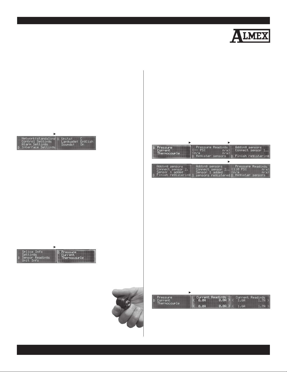
4.4. INTERFACE SETTINGS
ENTER
FIGURE 20 - INTERFACE SETTINGS
From the SG1 menu, users can change the way the menu displays information or reacts to selections. (SEE FIGURE 20)
4.4.1. TEMPERATURE UNITS
Sets the temperature units to either degrees Celsius or degrees
Fahrenheit.
(SEE FIGURE 20)
4.4.2. LANGUAGE
Sets languages to either English or Spanis
h. (SEE FIGURE 20)
4.4.3. SOUNDS
Turns the menu sounds ON or OFF. When a selection is made, an
alert will sound.
(SEE FIGURE 20)
5. Sensor Readings
ENTER
FIGURE 21 - SENSOR READINGS
From the menu, users can monitor all sensor readings including
pressure, electrical current, and thermocouple readings.
5.1. PRESSURE READINGS
SG1s come with wireless pressure sensors.
These sensors read between 8 and 299 psi at a
distance of up to 300 ft., when line of sight is not
obstructed. Sensors attach to Schrader valves in
line with the bag pressure. These valves are con
nected in one of three configurations:
Shaw Almex Industries | 1.800.461.4351 | www.almex.com
-
1. Directly attached to a tee fitting connected to each pressure bag.
2.
Attached to a manifold combining multiple pressure bags.
3. Connected directly to the pressurizing pump. In order to read
pressures, users must first register the sensors with the SG1.
After registration, the SG1 will continue to receive pressure
readings from that specific pressure sensor until either the
sensor registration process is repeated or until the pressure
sensor battery is completely depleted.
5.2. PRESSURE SENSOR REGISTRATION PROCEDURE
NOTE: Pressure Sensors can only be registered when there is
no splice in progress.
ENTER ENTER
MENU
FIGURE 22 - REGISTERING PRESSURE SENSORS
1. On the menu screen. Navigate to Sensors > Pressure
Sensors. Select “Enter” on the “Register sensors” line.
2. The LCD display will now show “Connect Sensor 1.” Con
nect the first pressure sensor you want to use to a pressure
source, and within 1 minute, the sensor will be registered.
3. The next prompt is: “Connect sensor 2.” Connect the second
sensor to a pressure source and wait until it is registered.
4. Up to four pressure sensors can be added. Press MENU at
any time to stop adding pressure sensors.
5. Press the “Reset” button after sensors have been registered.
6. To view the sensor readings, return to the Pressure Readings
screen. (SEE FIGURE 22)
NOTE: Pressure Sensors are battery powered and will run
out after use. The average life span is three years. Contact an
Almex distributor to purchase new pressure sensors.
-
5.3. CURRENT READINGS
ENTER
FIGURE 23 - CURRENT READINGS
1. CURRENT READING 2. NO CURRENT 3. ACTIVE CURRENT
The SG1 monitors and displays the total electrical current running
to each of the connected platens. Readings vary press to press.
(SEE FIGURE 23)
49900-038Revised - April 2014
9
5. Sensor Readings CONTINUED
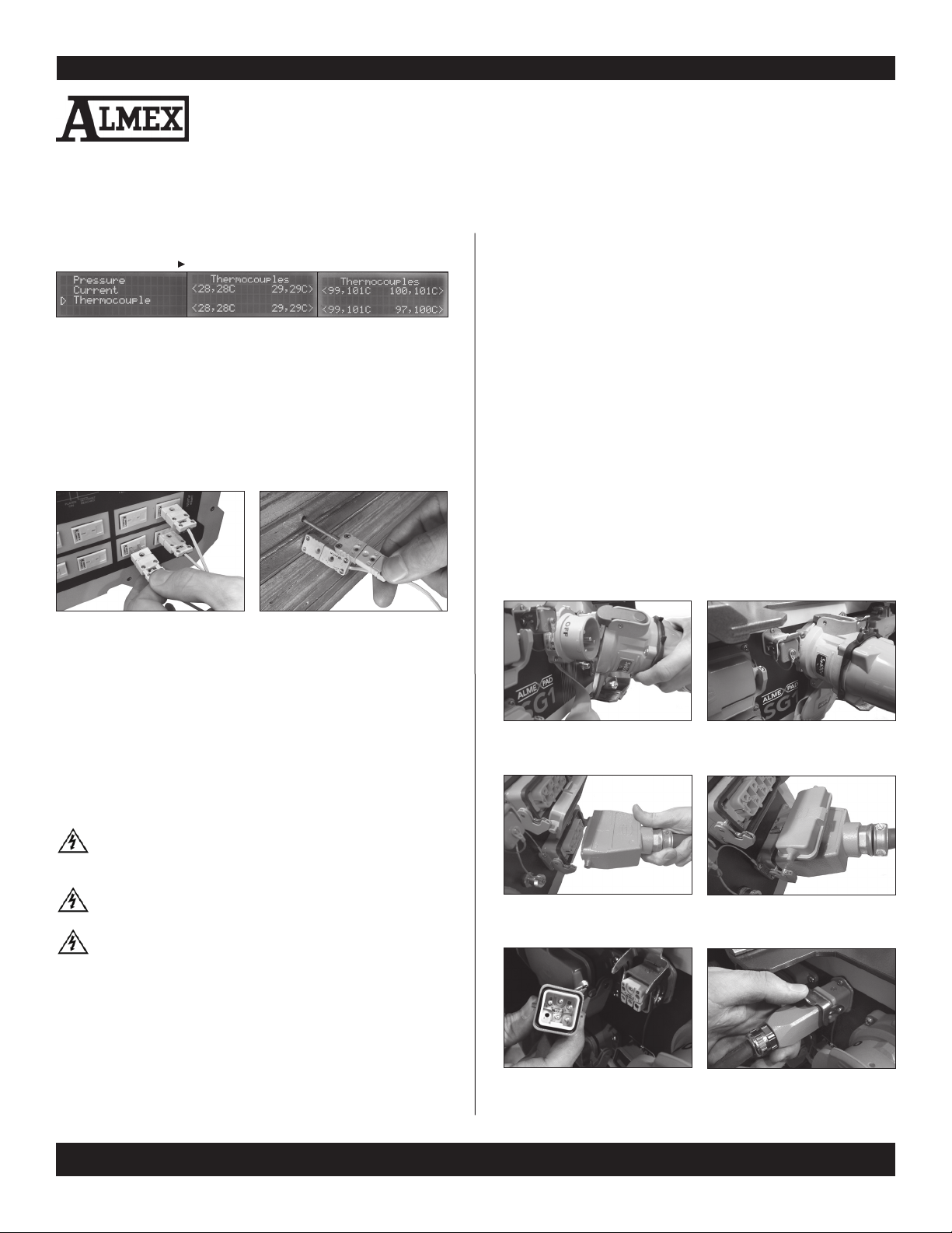
5.4. THERMOCOUPLE READINGS
ENTER
FIGURE 24 - THERMOCOUPLE READINGS
1. SENSOR READING 2. INTERNAL SG1 TEMP. 3. SPLICE TEMPERATURE
5.4. THERMOCOUPLE READINGS
Up to 8 thermocouple readings can be measured and displayed from the 8 thermocouple leads at the front of the SG1.
(SEE FIGURES 24, 25A & 25B)
NOTE: If a thermocouple is not connected; the reading
shown is that of the internal SG1 unit temperature.
FIGURE 25A - INSERT
THERMOCOUPLES INTO THE SG1
FIGURE 25B - INSERT
THERMOCOUPLES INTO THE PLATEN
6. Preparation
3. Connect the Blue Power Connector of the Supply Cable to the Power Main Input Receptacle on the
rear panel of the SG1. (See FIGURES 26A & 26B)
4. Lift the Platen Receptacle Covers on the rear panel of the
SG1 and connect the platen cables. (SEE FIGURE 27A &
27B) Press the plugs firmly into the receptacles and close the
latches to secure the plugs. When the cables are removed,
close the covers to protect the connector from contaminates
such as water or dirt.
5. Connect the pump or compressor if required. The connec
tors are keyed so that only an Almex pump with the correct
voltage can be connected. (SEE FIGURE 28A & 28B)
6. Connect the SG1 control cable to the power supply. Refer
to the electrical specifications indicated on the serial plate
and in the record of purchase. The SG1 will power on au
tomatically when connected to the power supply. To power
down (turn off) the SG1 control, simply disconnect it from
the power supply. (SEE FIGURES 26A & 26B)
-
-
6.1. UNPACKING
Carefully unpack the Switchgear control from the box and
inspect for damage. Any damage or shortage should be re
-
FIGURE 26A - REMOVE BLUE
POWER CONNECTOR COVER
FIGURE 26B - INSERT POWER CABLE
CONNECTOR UNTIL IT CLICKS
ported to the carrier and/or Shaw Almex Industries Limited
immediately.
6.2. CONNECTION ASSEMBLY
Safety: Ensure the voltage, phase and cycle on the
Switchgear control is the same as the power supply.
See serial number on rear panel of the SG1.
Safety: Never heat the vulcanizer unattended. Read
all safety information before turning on the SG1.
Safety: Do not turn power on until the SG1 and all
FIGURE 27A - OPEN PLATEN
CONNECTION LIFT COVER
FIGURE 27B - INSERT PLATEN
CONNECTOR FIRMLY
associated components are properly connected.
1. Ensure that the Auxiliary, Platen Set 1 and Platen Set 2 switch
-
es are in the OFF position.
2. Have a certified electrician install a suitable eletrical connec
tor to the non-terminated end of the power supply cable.
(SEE FIGURE 12) NOTE: For information on the voltage,
amperage and phase, refer to the electrical specifications,
located on the rear panel of the SG1.
Revised - April 2014 49900-038
10
1010
Shaw Almex Industries | 1.800.461.4351 | www.almex.com
FIGURE 28A - REMOVE AUXILLARY
CAP AND ALIGN PINS
FIGURE 28B - INSERT PLUG INTO
RECEPTACLE & SECURE WITH LATCH

7. Operation
7.1. HEATING THE VULCANIZER
CAUTION: The vulcanizer must be pressurized to at
least 5 psi (0.3 bar) before heating, or damage will oc
cur to the connected platen element on the vulcanizer.
-
7.1.1. AUTOMATIC HEATING
The SG1 can automatically follow a given splice recipe. The
parameters for a splice recipe can be set using two methods:
1. Using the Splice Monitor application on the ALMEXPAD.
2. Using the LCD user interface on the SG1.
To use the AUTOMATIC function, platen switches must be
turned to the AUTO position
OPTION 1
Using SpliceMonitor on the ALMEXPAD
Connect the SG1 to the ALMEXPAD using the USB cable or via
WiFi. On the ALMEXPAD open SpliceMonitor and connect to
the SG1. Set the desired splice parameters for the Dwell, Cure
and Cool phases and start the splice. Please see the ALMEX
PAD and SpliceMonitor Operator’s Manuals for more details.
-
OPTION 2
Using the SG1 Front Panel Display
ENTER ENTER
MENU
When all connected platens reach the Set Point dwell temperature, the platen begins the “At Dwell” phase. In this phase of operation the SG1 maintains the set temperature for the set time.
Remaining Dwell time can be viewed on the LCD display in the
“Splice Info” menu or on the ALMEXPAD Splice Monitor screen.
When the “At Dwell” phase is completed, the SG1 enters the
“To Cure Temperature” phase and heats up until all platens rise
to meet the Set Point cure temperature. In this phase the SG1
maintains the set temperature for the set time. (See FIGURE 1)
Once the Cure time elapses, the SG1 enters a “Cooling” state.
At this point, operators may pump coolant into the platens to
speed up the cooling phase. After all platens cool below the
Cooling temperature, the splice is complete.
7.1.2. MANUAL HEATING
If there is a temperature controller malfunction or platen temperature sensor failure, the platen can be heated manually by
turning the platen switch to the MANUAL position and holding
it there. (SEE FIGURE 5) When using this function, the platen
temperature should be manually monitored with thermocou
ples and/or stem thermometers.
-
7.1.3. COOLING
Manual cooling must be used with this version of the SG1.
See the User manual for the specific press being used.
NOTE: Automatic cooling is not available at this time.
ENTER ENTER
FIGURE 29 - AUTOMATIC HEATING
Navigate to the Splice Info submenu using the LCD user inter
face, from there, select the Splice Parameters option and set
the desired splice parameters for the Dwell, Cure and Cool
phases. Afterward, from the Splice Info sub-menu, press Start
Splice. (SEE FIGURE 29)
Safety: Once the splice has begun the platens will be
hot to the touch.
When the splice recipe parameters have been chosen and the
“Start Splice” has been selected, the SG1 will begin heating up
in the Dwell Phase.
When the Set Point is reached for each phase, the “Set Point
Reached” LED will illuminate. The SG1 and control tablet will
start timing the dwell and cure period from the time all appli
cable platens have reached the Set Point.
Revised - April 2014
-
-
Shaw Almex Industries | 1.800.461.4351 | www.almex.com
7.1.4. SPLICE RESUME
In the case of a power failure or interruption, the SG1 can
resume a splice. When the SG1 unit is repowered, the first
screen shown will give users an option to resume the most re
cent splice. Selecting “Yes” restores all splice parameters and
continues the splice from the time that the splice was halted.
Select “No” if you wish to start a new splice. (SEE FIGURE 30)
FIGURE 30 - RESUME SPLICE
-
8. Operation with
Multiple SG1s
8.1. DESCRIPTION
Up to four SG1s supporting 16 platens, can be networked together for the purpose of combining sectional presses to complete one large splice. When networked, SG1s can share sensor
readings and coordinate heating and cooling.
49900-038
11
8. Operation with Multiple SG1s CONTINUED
In an SG1 network, one unit is designated as a network master.
It is responsible for synchronizing communication between all
SG1s in the network. The Master has full control of the other
units and is the single point of contact for communication with
ALMEXPADs. The master SG1 can be identified because its
Network Master LED is emitting a solid, non-flashing light.
All other units are referred to as Slave units. These units have
less functionality and are for the most part controlled by the
master unit. They are identified by flashing LEDs.
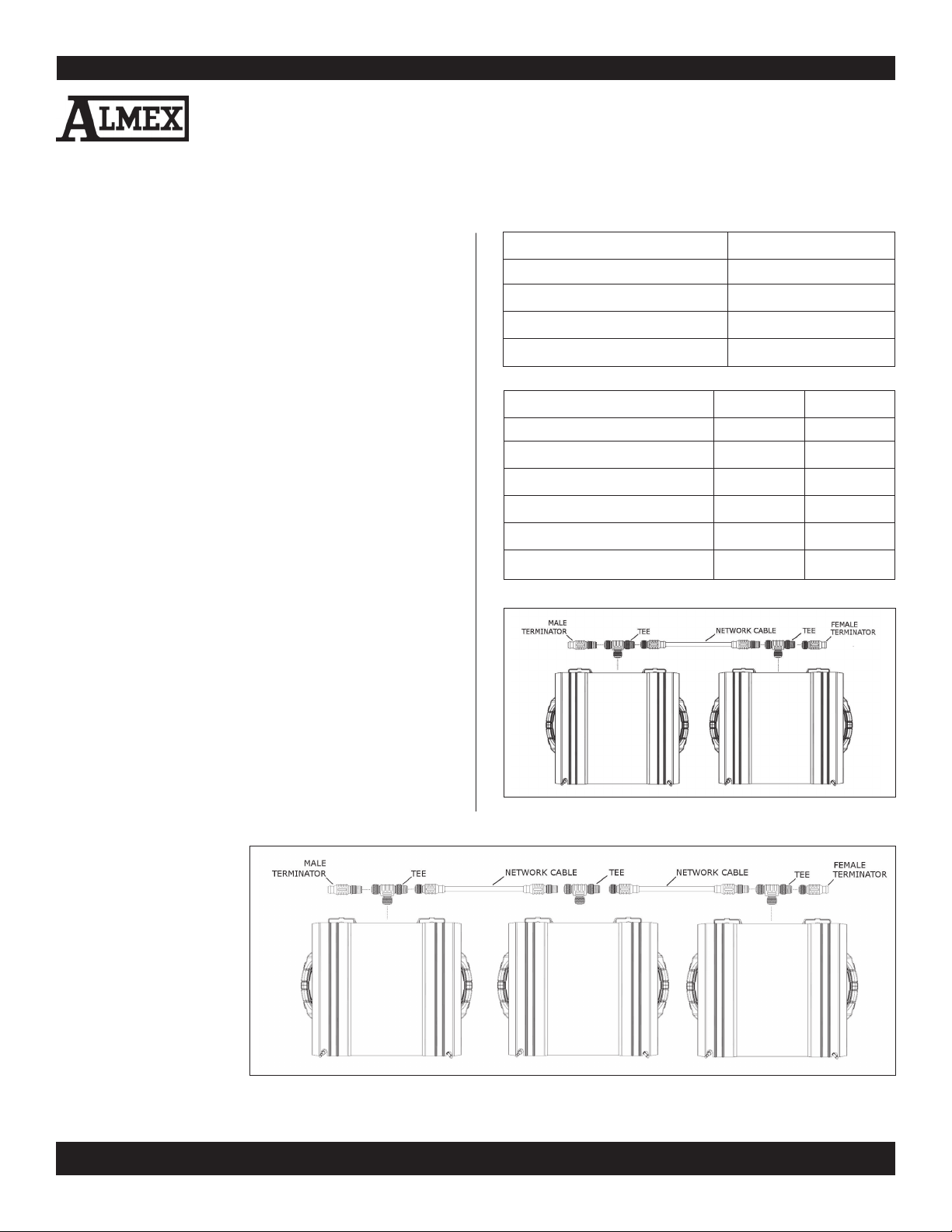
8.2. PREPARATION
The SG1s are connected via DeviceNet network cables. These
cables are industrial rated for use in electrically noisy environ
ments and are designed to be immune to inductive interference. The steps you will need to perform in order to form an
SG1 network are as follows:
1. Connect each tee fitting to the networking receptacle on the
rear panel of each SG1.
2. Connect the network cables in between adjacent SG1s.
3. Add the male and female terminators to the 2 unterminated
tees of the end SG1s. (See FIGURES 31 & 32)
4. Power up all SG1s.
5. Select a single SG1 to be the master. For best performance
select the central SG1 (one without a terminator in a network
with 3 or 4 SG1s). On that unit navigate to the “Settings”menu
and select the network type option to initialize the unit as the
“master”. Connected SG1s (unless they are active in a splice
operation) will automatically be configured as slaves. After
network configuration, the master can be operated in the
same way as a single basic unit. A splice can be configured
and started from the “Splice Info” menu. The master SG1
can communicate with
and be controlled by an
ALMEXPAD via USB or
WiFi.
6. The Platen Switches on
each unit must be set to
AUTO in order to oper
ate under a networked
splice.
-
-
ITEM QUANTITY
FEMALE TERMINATOR 1
MALE TERMINATOR 1
TEE FITTING 1 PER CONNECTED SG1
NETWORK CABLE 1 PER CONNECTED SG1
FUNCTIONALITY SLAVE MASTER
SET SPLICE PARAMETERS
START SPLICE
E-STOP SPLICE
MODIFY ALARMS
USB COMMUNICATION
WIFI COMMUNICATION
FIGURE 31: CONNECTIONS FOR AN SG1 NETWORK WITH 2 UNITS
•
•
• •
• •
•
•
FIGURE 32: CONNECTIONS FOR A NETWORK WITH 3 SG1 UNITS
Revised - April 2014 49900-038
12
Shaw Almex Industries | 1.800.461.4351 | www.almex.com
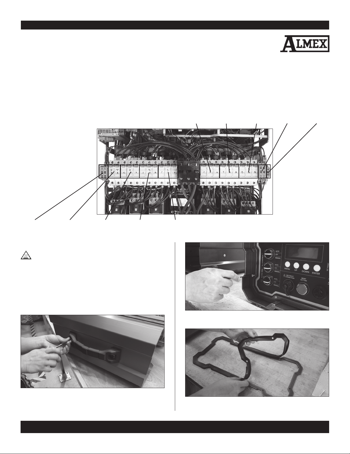
9. Maintenance & Repair
9.1. REPLACING FUSES
The SG1 has 25 fuses along the main fuse strip. Each platen connection and each auxiliary connection has 3 fuses. The transformer has
2 fuses and there are 5 low voltage fuses for the rectifiers, tempera
ture controller, and motherboard. (SEE FIGURE 33)
-
BOTTOM
LEFT PLATEN
FUSES
TOP LEFT
PLATEN
FUSES
RIGHT
AUXILIARY
FUSES
LOW
VOLTAGE
GLASS FUSES
MOTHERBOARD
BLADE
TYPE FUSE
TABLET POWER
GLASS FUSES
TRANSFORMER
FUSES
LEFT
AUXILIARY FUSES
PLATEN SET 2
BOTTOM FUSES
PLATEN SET 2
TOP FUSES
9.1.1. OPENING THE SG1
Safety: Disconnect the power supply and all other
cables before opening the SG1.
The SG1 Switchgear Control Box must be opened to replace
fuses. To access the circuits, a 5/16” hex allen key and a 1/8”
hex allen key are required.
NOTE: Each SG1 may sealed using one of two sealing processes.
1. A reusable moulded silicone gasket
2. Removable silicone caulk
FIGURE 33 FUSE DIAGRAM (TOP VIEW)
FIGURE 35 - STEP 2. USING THE 1/8” HEX ALLEN KEY, REMOVE ALL
BOLTS HOLDING THE FRONT AND REAR SEALING RINGS IN PLACE.
EIGHT
FIGURE 34 - STEP 1. USING THE 7/32” HEX ALLEN KEY, REMOVE
THE FOUR BOLTS SECURING THE HANDLES.
Revised - April 2014
Shaw Almex Industries | 1.800.461.4351 | www.almex.com
FIGURE 36 - STEP 3.
PROVIDED OR THE SILICONE RESIDUE.
REMOVE THE SEALING RING AND SILICONE GASKET
49900-038
13

9. Maintenance and Repair CONTINUED
9.1.1. OPENING THE SG1 (CONTINUED)
FIGURE 37 - STEP 4. PULL
THE CENTRAL TRAY OUT OF THE ENCLOSURE.
9.1.2. FUSE PLACEMENT
9.1.3. CLOSING THE SG1 (CONTINUED)
FIGURE 40 - STEP 7. BOLT BOTH HANDLES ONTO THE ENCLOSURE USING THE
FIGURE 41 - STEP 8 - OPTION 1.
7/32” HEX ALLAN KEY.
PLACE THE REUSABLE SILICONE GASKET
ONTO THE FRONT OR BACK PANEL OF SG1.
FIGURE
38 - STEP 5. FLIP UP THE REQUIRED FUSE HOLDERS.
REPLACE BROKEN FUSES WITH THE APPROPRIATE FUSE TYPE
(SEE 11. SG1 PARTS LIST)
9.1.3. CLOSING THE SG1
FIGURE 39 - STEP 6. PUSH THE CENTRAL TRAY INTO THE ENCLOSURE, BE
Revised - April 2014
14
CAREFUL TO AVOID PINCHING WIRES. ENSURE THAT THE
HANDLE BOLT HOLES ON THE TRAY ALIGN WITH THE
BOLT HOLES ON THE ENCLOSURE.
Shaw Almex Industries | 1.800.461.4351 | www.almex.com
FIGURE 42 - STEP 8 - OPTION 2. APPLY “DRAFT ATTACK” SEALANT TO THE
GAP BETWEEN THE FRONT PANEL AND THE ENCLOSURE.
FIGURE 43 - STEP 9. PROPERLY POSITION THE SEALING RING IN THE
SEALING GASKET OR ON THE DRAFT ATTACK AND SECURE
USING EIGHT 1/8” HEX ALLEN BOLTS.
49900-038

10. Troubleshooting
10.1. NO READING ON PLATEN SET 1 AND/OR PLATEN SET 2 TEMPERATURE INDICATORS
10.1. NO READING ON PLATEN SET 1 AND/OR PLATEN SET 2 TEMPERATURE INDICATORS
FAULT CORRECTION
FAULT CORRECTION
10.1.1. Power supply or cable is faulty. Ensure that the power cable is connected properly and that the power
supply is turned on.
10.1.2. Control circuit fuse has opened. Disconnect power, open control box and replace fuses.
See “9. Maintenance and Repair.”
10.2. “ERR” DISPLAYED ON PLATEN SET 1 AND/OR PLATEN SET 2 TEMPERATURE INDICATORS
FAULT CORRECTION
10.2.1.
cables are connected and secured properly.
10.2.2. Loose connection in cable or platen Remove electrical connector insert from platen housing and tighten
10.2.3.
Platen not connected.
connector. all connections.
RTD temperature sensor is faulty.
Err is displayed any time a platen cable is not connected. Ensure the platen
Refer to the Maintenance Section in the Operator’s Manual for the Almex Press .
10.3. PLATENS NOT HEATING
FAULT CORRECTION
10.3.1. Power supply or cable is faulty. Ensure that the power cable is connected properly and that the
power supply is turned on.
10.3.2. Platen switch OFF. Turn platen switch to AUTO or MANUAL.
10.3.3. Temperature set improperly. Ensure that Temperature Set Point is correct.
10.3.4. No continuity between SG1 and platen.
10.3.5. Loose connection in SG1 control panel. Disconnect power supply, open the control cabinet and check
for loose wire connections.
Check power supply, fuses (inside panel) and cable connections.
10.3.6. Faulty RTD temperature sensor in platen. Refer to the Maintenance Section in the Operator’s Manual of
the Almex Press.
10.3.7. Faulty heating element in platen. Refer to the Maintenance Section in the Operator’s Manual of
the Almex Press.
10.3.8. Faulty Contactor in SG1 control panel.
10.3.9. Loose connection in cable or
platen connector.
10.3.10. Faulty temperature controller in SG1
control panel.
Revised - April 2014
Replace Contactor. (SEE SG1 PARTS LIST & SCHEMATIC DIAGRAM)
Remove electrical connector insert from housing and tighten all connections.
Replace Omron Temperature Controller.
Shaw Almex Industries | 1.800.461.4351 | www.almex.com
49900-038
15

10. Troubleshooting CONTINUED
10.4. VULCANIZER OVERHEATING
FAULT CORRECTION
10.4.1. Temperature set improperly. Ensure that Temperature Set Point is correct. (SEE SECTION 7.1.1.)
10.4.2. Faulty Contactor in SG1 control panel. Replace Contactor. (SEE SG1 PARTS LIST &SCHEMATIC DIAGRAM)
10.4.3. Faulty RTD Temperature Sensor in platen. Refer to the Maintenance Section in the Operator’s Manual
of the Almex Press.
10.4.4. Faulty Temperature Controller in SG1 Replace Omron Temperature Controller.
control panel.
10.5. UNIT FAILS TO CREATE SG1 NETWORK
FAULT CORRECTION
10.5.1. Improper network configuration. Ensure network is connected according to (SEE SECTION 8)
10.5.2. Faulty network connectors. Check network cables for continuity. Replace cables and terminators
if necessary.
10.5.3. Faulty communication on SG1 motherboard Contact Shaw Almex.
NOTE: IF TROUBLESHOOTING STEPS HAVE BEEN PERFORMED AND THE PROBLEM PERSISTS,
PLEASE CALL SHAW ALMEX FOR FURTHER SERVICE. (SEE SECTION 12)
HEATING ELEMENT RESISTANCE
RTD PROBE RESISTANCE
FIGURE 44 - PLATEN CONNECTOR - REFERENCE ONLY
Revised - April 2014 49900-038
16
Shaw Almex Industries | 1.800.461.4351 | www.almex.com

11. SG1 Parts List
ITEM QTY DESCRIPTON PART #
PER UNIT
Power - 60A Option 1 600 V, 60 A Connector Body - DSN60 11-PWR-INC-08
1 600 V, 60 A Handle - DSN60 11-PWR-INC-09
1 600 V, 60 A Handle - DSN60 (Australia only) 11-PWR-INC-13
4 600 V. 3-phase, 18 A midi-contactor 11-PWR-OUT-04
2 600 V, 3-phase 9 A midi-contactor 11-PWR-OUT-03
2 250 VAC, 1 A 5 x 20 mm fast-acting glass fuse 11-PWR-INC-13
6 600 VAC, 20 A CC-type fuse (In fuse blocks 1 - 4) 11-PWR-FUS-04
2 600 VAC, 9 A CC-type fuse (In fuse blocks 5 - 6) 11-PWR-FUS-02
2 600 VAC, 1 A FNQ-CC type fuse (In fuse block TX) 11-PWR-FUS-01
Power - 100A Option 1 Metric DR100 Poly Receptacle - 600 V 100 A 3P+G 11-PWR-INC-02
1 Metric DR100 Poly Handle with built-in draw grips 11-PWR-INC-03
4 600 V 3-PHASE, 32A midi-contactor 11-PWR-OUT-02
2 600 V, 3-phase 9 A midi-contactor 11-PWR-OUT-03
2 250 VAC, 1 A 5 x 20 mm fast-acting glass fuse 11-PWR-FUS-04
6 600 VAC, 30 A CC-type fuse (In fuse blocks 1 - 4) 11-PWR-FUS-03
2 600 VAC, 9 A CC-type fuse (In fuse blocks 5 - 6) 11-PWR-FUS-02
2 600 VAC, 1 A FNQ-CC type fuse (In fuse block TX) 11-PWR-FUS-01
Pressure Sensing 2 TPMS Wireless Pressure Sensors, 250 psi 11-WLS-PSN-02
2 Schrader Valve for TPMS Wireless Pressure Sensor 11-WLS-VLV-01
Thermocouple Temperature 8 10’ K-type Thermocouple extension cable, mini male, mini female 11-THR-OTH-02
Sensing Optional 8 12” length, 1/8” diameter K-type round probe, mini male 11-THR-OTH-01
Switchgear Networking 1 DeviceNet Female Terminator 11-NET-OPA-01
Optional 1 DeviceNet Male Terminator 11-NET-OPA-02
N-1 DeviceNet Chordset Straight Male/Female 8M (thin) 11-NET-OPA-03
1 DeviceNet Mini T-Connector 11-NET-OPA-04
Miscellaneous 1 DAP Draft Attack sealant caulking 11-STR-ENC-11
1 Dust Cover 11-STR-ENC-10
1 Silicon Gasket 11-STR-GAS-01
1 SG1 Protective Carrying Case 11-STR-ENC-12
Documentation 1 Operating Manual
1 Commissioning Report (QA)
Revised - April 2014
Shaw Almex Industries | 1.800.461.4351 | www.almex.com
49900-038
17

12. Service
12.1 EMERGENCY SERVICE
Contact: Service Department
Telephone: 705-746-5884
Toll Free: 1-800-461-4351
(Canada and U.S. Only)
Fax: 705-746-9484
SHAW ALMEX INDUSTRIES LIMITED
Mail: P.O. Box 430, Parry Sound
Ontario, Canada P2A 2X4
Email: service@almex.com
12.2 RETURN OF GOODS AUTHORIZATION
The service department of Shaw Almex Industries Limited MUST
be contacted for the necessary authorization and documentation
prior to returning goods to the factory.
The service department may be reached at the numbers shown
in the left column.
12.3 GUARANTEE
Your ALMEX Switchgear Box is guaranteed against defective
parts, material and workmanship for a period of 12 months
from the date of purchase. For complete details, refer to the
Warranty Card.
13. Schematic Diagrams
FIGURE 45 - SG1 WIRING SCHEMATIC - 60A
Revised - April 2014 49900-038
18
Shaw Almex Industries | 1.800.461.4351 | www.almex.com

13. Schematic Diagrams CONTINUED
FIGURE 46 - SG1 WIRING SCHEMATIC - 100A
Revised - April 2014
Shaw Almex Industries | 1.800.461.4351 | www.almex.com
49900-038
19

SHAW ALMEX INDUSTRIES LIMITED
1-800-461-4351
www.almex.com
Revised - April 2014
49900-038
 Loading...