

Almatec A 08,A 50 Operating and Installation Instructions
A-Series
A 08 – A 50
Pneumatic Diaphragm Pumps made of Polymer Material
Operating and
Installation Instructions
ought to be studied before installing the pump

A-SERIES · page 2
Introduction
The ALMATEC Maschinenbau GmbH is certified as a modern, quality-orientated enterprise according to
EN ISO 9001. Before release for dispatch, any pump of the A-Series has to undergo an extended final control.
The performance data registered during this are archiv ed in our records and can be read back at any time.
Before putting any pump into operation, make sure, that the materials of construction are resistant to the
chemical to be pumped. To check this, the exact pump code is required. This code, as well as the serial number, can be found in the following. Besides, these data are noted on the identification plates on the pump itself.
Pump code Serial-No.
Here is an example to clarify the system of the ALMATEC pump codes:
A 15 T T T - B
Optional equipments:
B Barrier chamber
C Stroke counting
D Diaphragm monitoring
F Flange connection PN 10
R Back flushing system
Type and material E Ball valves, EPDM
of product valves: T Ball valves. PTFE
S Ball valves, stainless steel
Y Cylinder valves, PE
Z Cylinder valves, PTFE
Diaphragm material: E EPDM
T PTFE/EPDM-compound
Housing material: E PE
F PE-conductive
T PTFE
U PTFE-conductive
Size and port dimension
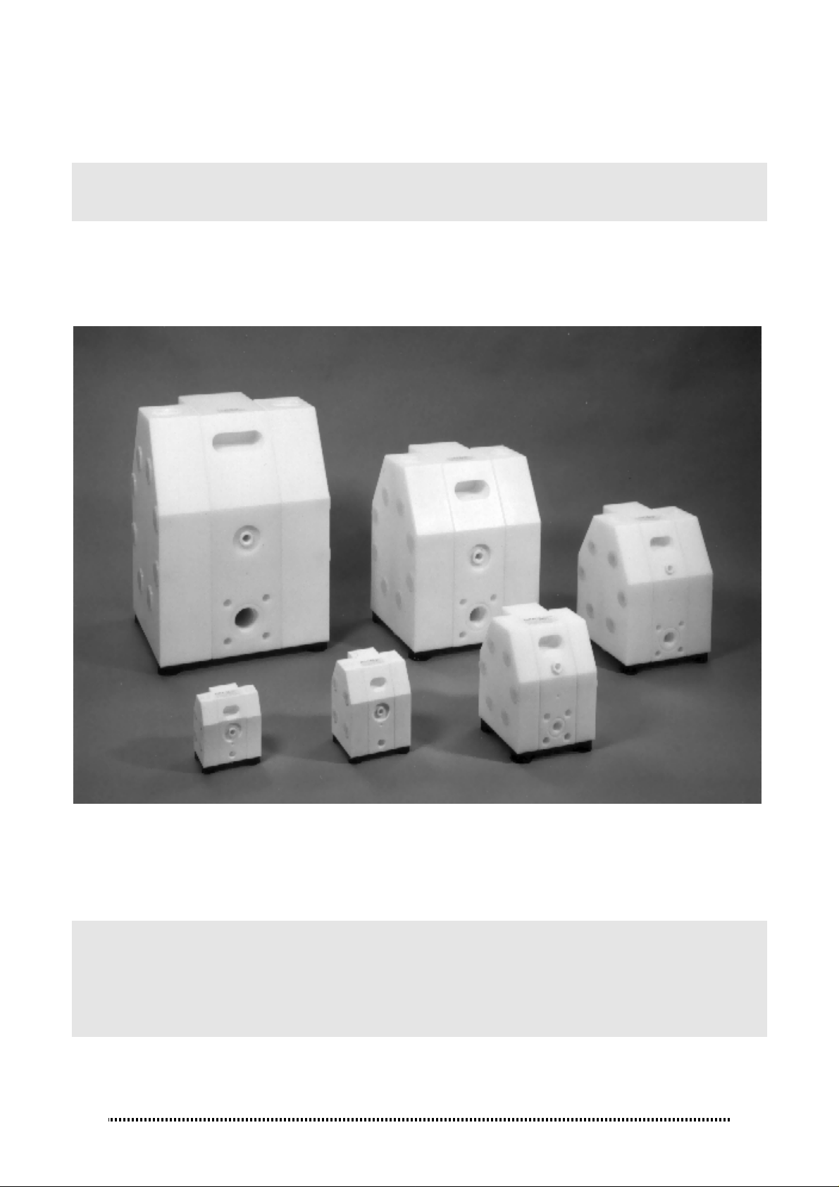
ALMATEC Pneumatic diaphragm pump, A-Series
For inflammable liquids as well as for applications in explosion protected areas, only pumps with housings and
fittings in conductive polymer materials may be used. Pneumatic diaphragm pumps of the A-Series with the
housing codes F (PE-conductive) and U (PTFE-conductive) meet this requirement. The pump has to be
grounded. An earthing connection to ground the pump is included in the center housing [2]. The connection of
all other housing parts is conductive, therefore it is not necessary to ground single parts.
The number in brackets, which is added to every part mentioned in the following explanations, refers to its
position in the spare part list and the exploded view.
Product ports
The product ports are integrated into the center housing [2]. Different port configurations can be obtained. The
standard configuration of the A-Series at delivery is with the suction inlet horizontally at the bottom and the
discharge outlet horizontally at the top. Further possible configurations:
• Suction inlet vertically at the bottom, the discharge outlet horizontally at the top:
To obtain this configuration, the plug of the center housing [8] has to be removed and set in the standard
inlet.
• Suction inlet horizontally at the bottom, the discharge outlet vertically at the top:
Unscrew the housing bolts [15], take off the side housings [1] and turn the center housing [2]. Remount
the pump and adjust the plug [8] accordingly.
The mounting and dismounting of the pump will be described further on.

A-SERIES · page 3
Technical data
Dimensions (mm): length
width
height
Nominal port size (NPT)
Air connection
Weight (kg): PE
PTFE
Max. particle size of solids (mm)
for pumps with ball valves
Suction lift, dry (mWC):
cylinder valves
ball valves
Suction lift, wet (mWC)
Max. operating pressure (bar) 7 7 7 7 7 7
Max. operating temperature (°C):
PE
PTFE
Theoretical displacement volume
per single stroke (l)
A 08 A 10 A 15 A 25 A 40 A 50
90
113
129
1/4“
R 1/8
-
2
2 3 4 6 9 11
1
0.5
9
-
100
0.0075 0.0215 0.1 0.34 0.98 2.6
110
127
169
3/8“
R 1/8
-
4
2
1.5
9
-
100
166
176
240
1/2“
R 1/4
5
10
3
2
9.5
70
120
220
231
320
1“
R 1/4
13
25
4
3
9.5
70
120
280
326
432
1 1/2“
R 1/2
29
60
5
4
9.5
70
120
360
396
552
2“
R 1/2
58
120
5
4
9.5
70
120
Sound pressure level acc. to DIN 45635,
part 24, depending on the operating data
[dB (A)]: driving pressure 3 bar
driving pressure 5 bar
driving pressure 7 bar
These technical data are for ALMATEC A-Series pumps without optional equipments.
Installation and Operation
In general, the pump has to be connected load free. Neglecting this causes leakage and maybe even
damages. To avoid vibrations, pulsation dampers and compensators are recommended. Before connecting the
pump, take the yellow blind plugs out of the suction and discharge connections as well as the air inlet [19] in
the center housing [2]. The connections of ALMATEC pneumatic diaphragm pumps in polymer materials have
slightly tapered threads. Use threadseal only sparingly, otherwise the connections could be damaged.
The nominal width of the connection pipes has to be chosen in accordance to the connections of the pump.
A smaller piping can cause cavitation (suction line) as well as a loss of performance (suction and discharge
line). In case the pipe is too big, the dry suction capacity of the pump can decrease. Connect the suction line to
the lower connection in the center housing [2]. Seal the suction line diligently; hosepipes should be suitably
armoured. A suction line continuously rising will prevent the formation of air locks in the line which would affect
the suction lift.
The air inlet [19] is located in the middle of the center housing [2]. To supply the pump with driving air
sufficiently, the pipe diameter should match the size of the air inlet. Take care that no dirt or particles can
intrude into the pump during the connection, as these can accumulate inside the pump and can cause
malfunctions. An air filter [20] directly behind the air inlet [19] (not included in A 08 and A 10) prevents the entry
of bulk particles.
The integrated air control system PERSWING P® is a precision-control that requires oil-free, dry and clean
compressed air for optimal function. If humidity is expected, a water separator or air dryer has to be fitted to
protect the pump from blocking by ice. The ideal condition is the dewpoint of air at -20°C. In humid
surroundings, icing from the outside may occur despite the driving air is dried. If so, a prolonged waste-airexhaust (ca. 500 mm by pipe or hose) can be helpful. When installing the pump into boards or cabinets, it has
to be ensured that cold air does not get caught behind the muffler.
68-70
71-74
71-76
68-70
71-73
72-75
68-71
73-75
74-78
69-71
71-75
73-76
63-65
64-68
69-74
65-70
69-74
73-78
 Loading...