

Page 1
FN2
FNKS
Alltrax Inc
1111 Cheney Creek Rd
Grants Pass, Or, 97527
Direct: 541-476-3565
Fax: 541-476-3566
Alltrax XCT Adapter Wire Kit for Function Knob Boxes: FN2 and FNKS
Club Car IQ with 16 pin IQ Controller
File: DOC105-001-B_Install Doc, FN Knob Box CC-IQ to XCT.pdf, Released Rev B, EC-081616
ALLTRAX PN: KIT-CBL511-004_FN ADAPTER CC-IQ
The XCT motor controllers have “User Inputs” or commonly called Personality Switches that allow for set user
profiles or interactive adjustments of Speed or Regen while driving. XCT Controllers PRIOR to AUGUST 2016 may
not have the FN 3-pin integrated connector in J4-J5-J6 connector well (See WEB SITE for serial number cutoff).
This adapter kit is for all older controllers. Use TOOLKIT software (Version 3.0 or above) to enable the new
Function Control features. Newer XCT controllers built ON or AFTER August 2016 will have the 3-pin connector to
directly plug the FN boxes into the XCT controller J4-J5-J6.
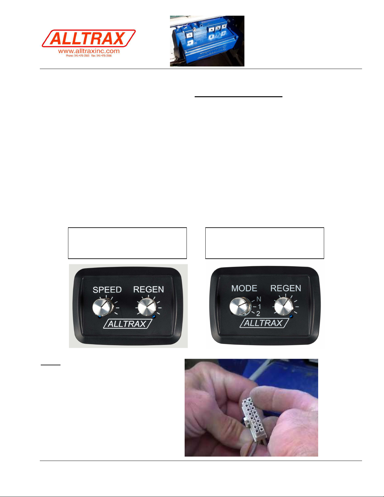
Two different Function boxes are available, FN2 for dual pot Speed/Regen or FNKS with Mode Switch + Regen
knob.
This adapter wire kit has 3 wires to plug into the OEM wire harness to gain access to the user inputs on the XCT.
Install time for this wire harness adapter kit is approximately 5 minutes.
Steps:
1. Disconnect positive battery terminal.
2. Carefully unplug the 16 pin connector
from the XCT-IQ controller.
Dual Potentiometer
1-MODE Rotary Switch
1-Potentiometer
P/N: Doc105-001-B_Install CC-IQ FN Knob Box Adapter Page 1 of 2
© Alltrax Inc. 2016
All Rights Reserved
Page 2
PIN 11
TAB
Alltrax XCT Adapter for ClubCar IQ
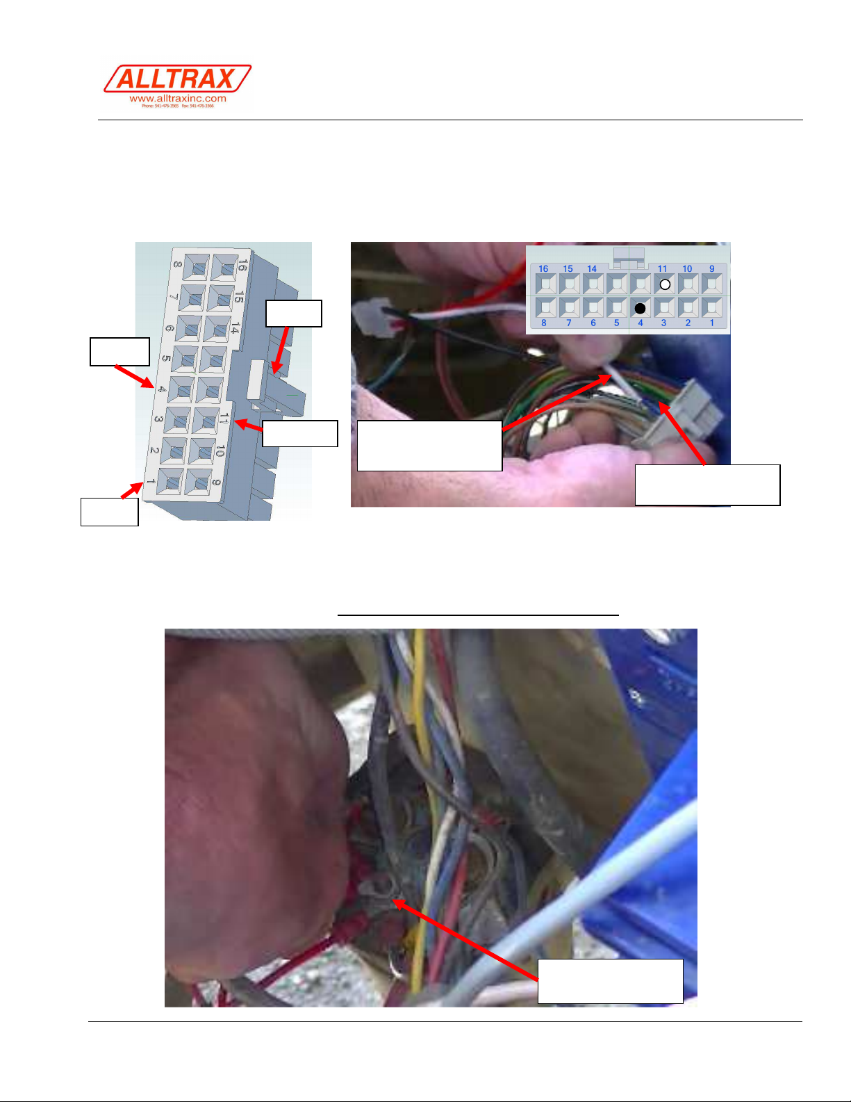
3. At the rear of the connector, we will be inserting two wires into the connector, Pin 4 and Pin 11. However,
some IQ carts (DS) may have a wire inserted into pin 4, although it’s not used by the Club Car computer,
special tools are required to remove the MOLEX pins from the 16 pin connector, so we can cut and splice
this wire (about 6” back) and splice the BLACK FN knob box interface wire used for the XCT into PIN 4.
Crimp a “dead end” crimp onto the other cut end to prevent it from shorting to something.
PIN 4
WHITE wire PIN 11
Near TAB
BLACK wire PIN 4
PIN 1
4. The RED WIRE is KSI which can be connected to the small SOLENOID COIL POSITIVE terminal. Note:
Some aftermarket solenoids have a different lug or faston, cut the suppled ring terminal off the red wire
and crimp whatever fits your application for the POSITIVE COIL wire.
5. Connect the 3-pin plug of the FN box to the controller interface wire you just installed.
6. Reconnect battery terminal and proceed to the FN Knob Box instructions.
RED wire COIL
POSITIVE
P/N: Doc105-001-B_Install CC-IQ FN Knob Box Adapter Page 2 of 2
© Alltrax Inc. 2016
All Rights Reserved
 Loading...