

Page 1
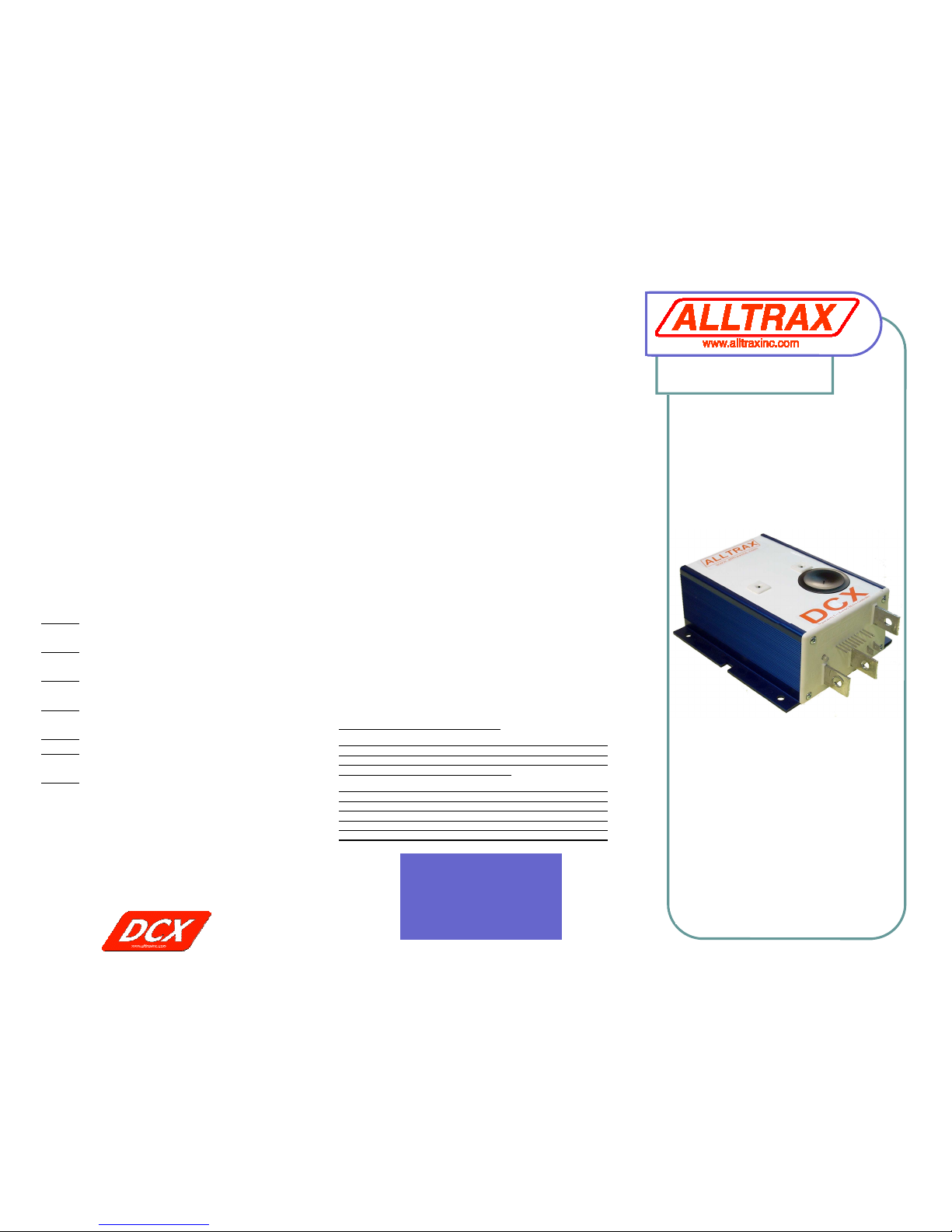
DCX
Mini-Manual
For Golf Car Applications
LIMITED WARRANTY
A n E n g i n e e r e d S o l u t i o n
LED Status Indicator
LED Blink Codes:
At power up, # of green blinks indicates
configured throttle type:
1 Green = 0-5k
4 Green = EZ-GO inductive (ITS)
7 Green = CLUBCAR 5K-3-wire
Normal display status:
Solid Green: Controller ready to run
Solid Red: Controller in programming mode
Solid Yellow: Controller throttle is wide
open, controller is supplying max output,
and is not in current limit.
Trouble Shooting
Error code display:# of RED blinks
indicates any error conditions that might
exist:
1 Red = Throttle Position Sensor Over
Range. Check for open wires.
2 Red = Under Temperature. Controller
below -25C
3 Red = HPD. Throttle hasn't gone to
zero during this power on cycle.
4 Red = Over Temperature. Controller
over 95C
5 Red = Open Field
6 Red = Battery Under Voltage detected.
Battery V < under voltage slider
7 Red = Battery Over Voltage detected.
Battery V > overvoltage slider
Doc100-006-B_OP-DCX-Mini-Man.pub, 12-1-2010
Alltrax, Inc.
1111 Cheney Creek Rd
Grants Pass, OR. 97527
Phone: 541-476-3565
Fax: 541-476-3566
www.alltraxinc.com
• Programmable
• 300, 400, & 600 Amp
• 24 to 48 Volt DC
• Regenerative Braking
• For Shunt Wound Motor
WARRANTY:
Alltrax, Inc., (hereafter Alltrax) warrants that the product purchased is
free from defects in materials or workmanship for a period of 2 years
from the date of manufacture. This warranty does not apply to defects
due directly or indirectly to misuse, abuse, negligence, accidents, repairs, improper installation, submersion, alterations or use contrary to
any instructions provided by Alltrax in verbal or written form.
In the event you should need warranty repair, contact Alltrax at (541)
476-3565 to receive warranty service authorization instructions for
returning the defective product to Alltrax for evaluation. Products or
parts shipped by customer to Alltrax must be sent postage paid and
packaged appropriately for safe shipment. Alltrax is not responsible for
customer products received without warranty service authorization and
may be rejected.
Alltrax reserves the right to repair or replace merchandise at its option at
no cost to the customer, except for shipping costs of sending the defect
item to Alltrax. Replacement shall mean furnishing the customer with a
new equivalent product to the defective item. Alltrax also reserves the
right to make changes to any of its products or specifications without
notice.
Alltrax assumes no liability for applications assistance or customer
product design. Customers shall be responsible for evaluating the
appropriateness of the use of any Alltrax product in any application.
Customers shall provide adequate design and operating safeguards that
are in compliance with standard practices of other similar applications or
any standards of any governing agency.
THIS IS ALLTRAX INC.’S, SOLE WARRANTY.
NO REPRESENTATIVE EMPLOYEE, DISTRIBUTOR OR DEALER OF
ALLTRAX HAS THE AUTHORITY TO MAKE OR IMPLY ANY WARRANTY, REPRESENTATION, PROMISE OR AGREEMENT, WHICH
IN ANY WAY VARIES THE TERMS OF THIS LIMITED WARRANTY.
ALLTRAX PRODUCTS SOLD TO CUSTOMER ARE INTENDED TO
BE USED ONLY IN THE APPLICATION SPECIFIED BY THE CUSTOMER TO ALLTRAX. ANY OTHER USE RENDERS THE LIMITED
WARRANTY EXPRESSED HEREIN AND ALL IMPLIED WARRANTIES NULL AND VOID AND SAME ARE HEREBY EXCLUDED.
DISCLAIMER OF IMPLIED WARRANTIES
ALLTRAX, INC., SHALL IN NO EVENT BE LIABLE FOR DEATH,
INJURIES TO PERSONS OR PROPERTY, OR FOR INCIDENTAL,
CONTINGENT, OR CONSEQUENTIAL DAMAGES ARISING FROM
THE USE OR MISUSE OF OUR PRODUCTS.
EXCEPT SPECIFICALLY PROVIDED HEREIN, THERE ARE NO
OTHER WARRANTIES, EXPRESS OR IMPLIED, INCLUDING, BUT
NOT LIMITED TO, ANY IMPLIED WARRANTIES OF MERCHANTABILITY OR FITNESS FOR A PARTICULAR PURPOSE. HOWEVER,
SOME STATES DO NOT ALLOW LIMITATIONS ON HOW LONG AN
IMPLIED WARRANTY LASTS, SO THE PRECEDING EXCLUSION
Page 2
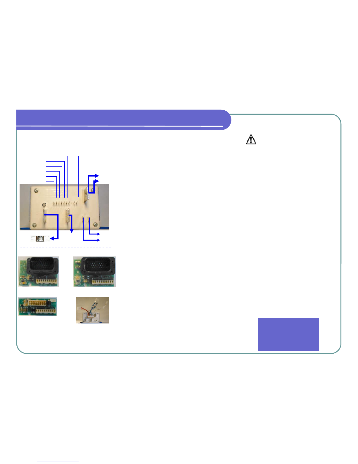
DCX Wiring Diagram ControllerPRO
ControllerPRO is free user friendly software for
customizing your Alltrax DCX Controllers.
Download your copy of ControllerPRO from
www.alltraxinc.com
Configuration
WARNING: Disconnect all battery charging
sources while programming your DCX controller.
The controllers RS-232 serial port is referenced
to the B- battery connection.
Beware of any possible ground loop faults
between your computer and the controller
which could damage both the DCX Controller and PC, or cause personal injury.
Hardware: Use a STRAIGHT-THROUGH DB-9
pin / RS-232 serial interface cable to connect the
controller to the PC. Alternatively use the preferred DB-9 pin RS-232 serial port to USB
adapter.
The DCX controller must be powered before the
ControllerPRO program will have any effect.
Before programming the DCX, READ THE
SAFETY NOTES BELOW. For bench programming prior to installation, a fused 18V or higher
battery may be used to power the controller.
Connect battery negative to the B- bus bar, battery positive to pin 5+6, 9+10 (Pin 8 is blank).
If you see an error “Motor Controller is Not
Responding”, verify the controller is powered
up and the connections are inserted correctly. If
the error message continues, uninstall then
reinstall the drivers for the communications cable. If the problem persists, contact Alltrax Technical Support.
Safety Notes:
Alltrax recommends that all motor controller
applications have a fuse in the battery circuit.
Many vehicles do not have a fuse, and will
need to have one installed. The following
fuses manufactured by Bussman or Littelfuse
are acceptable: For controllers rated at 400
amps or less use ANN250. On controllers
rated at 450 amps or more use ANN400. [See
Doc100-016-A_OP-Fuse-Install-Guide.doc]
Alltrax also recommends a diode across the
coil of the solenoid if it is not already installed.
A minimum of a 100V 1A diode (a 1N4004 is
suitable) is required. See complete wiring diagrams for orientation.
Working on electric vehicles, sudden unexpected events can occur, it’s recommended
to:
• Place the drive axle on jack stands—
wheels off the floor
• When working on wiring or batteries, always remove rings and watches and use
the proper safety equipment, eye protection, and insulated tools
• Never connect a computer while the vehicle is being charged
• Disconnect batteries before installing or
working on the controller
For complete instructions and wiring diagrams for other configurations and vehicles
please download our DCX Operators Manual from www.alltraxinc.com
Alltrax, Inc.
1111 Cheney Creek Rd
Grants Pass, OR. 97527
Phone: 541-476-3565
Fax: 541-476-3566
1 2 3 4
M-
B+
MOTOR A2
BATTERY +
MOTOR A1
B-
BATT
(-)
BLK
FUSE
1-THROT-1
2-THROT-2
3-HORN
4-REVERSE
5-FOOT SW
6-KEY SW
7-SOL COIL
10-B+ PWR
9-LOGIC B+
5 6
7 9 10
MOTOR S1
MOTOR S2
LED
F1 F2
QUICK INSTALLATION GUIDE
CLUB CAR - IQ PDS
YAMAHA - G19 CLUB CAR - PD PLUS
 Loading...