


AC-2000 Series Colposcope
User's Manual
Version: B3
14/09/2020
(Please read the instruction carefully before using it)
Alltion (Guangxi) Instrument Co., Ltd.
AC2000-UM02-EN

Product Information:
Product Name: Colposcope
Product Model: AC-2000 series
Date of Manufacture: Please see the instrument label
Manufacturer:
Alltion (Guangxi) Instrument Co.,Ltd.
Manufacturing Address: No. 10, 3 Road, Industrial Park, Wuzhou, Guangxi
E-Mail: sales@alltion.com or sales@alltion-microscope.com
Phone: +86-774-2836101
Fax: +86-774-2836192
Postal Code: 543000
Website: http://www.alltion.com
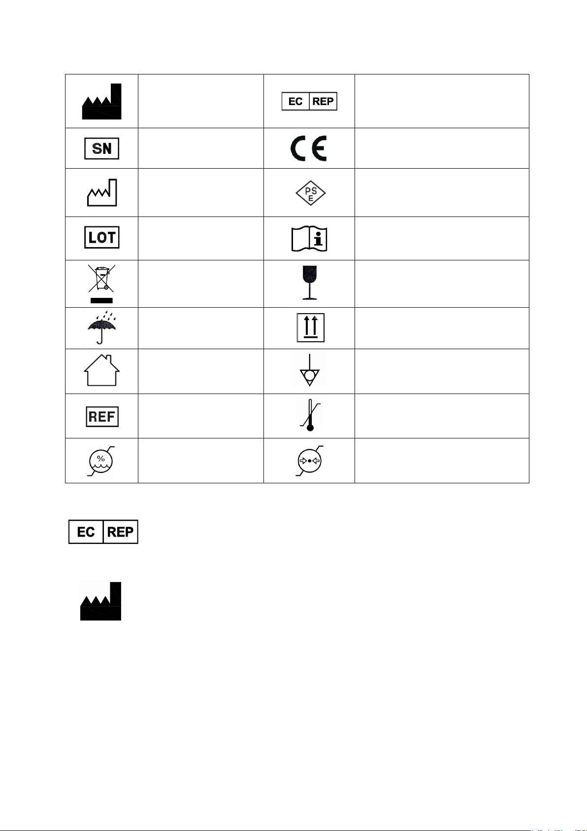
Symbols、labels and information:
Keep in a cool, dry
Alltion (Guangxi) Instrument Co., Ltd
Obelis s.a
Bd. Général Wahis 53 1030 Brussels, BELGIUM
Manufacturer
Serial number
Date of manufacture
Lot number
WEEE disposal
place
For indoor use
Authorized representative
in the European community
Medical Device complies
with Directive 93/42/EEC
PSE label
Consult instructions for use
Fragile, handle with care
Upward
Equipotentiality
Imported by:
Product code
Moisture limitation
Alltion Building, NO.10, 3rd Road, Wuzhou Industrial Park,
Wuzhou, Guangxi, China 543000
Made in China
Temperature limitation
Atmospheric pressure
limitation
GIMA S.p.A. - Via Marconi, 1 - 20060 Gessate (MI) - Italy
Security Warning
For using the instrument safely in a correct way and ensuring the instrument in a good
state ,please read this instruction carefully before operating .
It shall change some components to improve the quality and performance of
instrument. Therefore, it may has some different with the instruction. Please know that
the stander equipment be provided by factory shall prevail.
Please attach importance to and perform the contraindications
and announcements
In order to prevent the instrument from tipping during handling,
please keep the instrument at the lowest position.
Tilting Base: Do not place the instrument on a surface that is
more than 5 degrees. There is a risk of imbalance.

Contents
1 Intrduction ........................................................................................................................................................... 1
1.1 Product Feature ..................................................................................................................................... 1
1.2 Adaptation of Product .......................................................................................................................... 2
1.3 Product Formation ................................................................................................................................ 2
2 Security ................................................................................................................................................................ 2
2.1 Intended Use .......................................................................................................................................... 2
2.2 The Environment For Use ................................................................................................................... 3
2.3 Feature of Security ............................................................................................................................... 3
3 Instruction For Colposcope ........................................................................................................................... 4
3.1 Three-Step Colposcope(L Stand) ................................................................................................ 4
Three-Step Colposcope(Upright Stand) .................................................................................... 6
3.2
3.3 Indications for Use ................................................................................................................................ 8
3.4 Features ................................................................................................................................................... 8
4 Installation of Colposcope ........................................................................................................................... 8
4.1 Contents of Box ..................................................................................................................................... 8
4.2
Removing the Colposcope From the Box .................................................................................... 8
4.3 Setting Up the Colposcope ................................................................................................................. 9
5 Adjustment of the Eyepieces ......................................................................................................................... 9
5.1 To A d just the IPD (5C) .......................................................................................................................... 9
6 Adjustment of the Diopter Knobs ............................................................................................................... 10
7 Colposcope Instructions for Use ................................................................................................................. 11
8 Selecting Your Preferred Level of Magnification .................................................................................... 12
9 Integrated Video Camera .............................................................................................................................. 13
10 Storage and Precautions .......................................................................................................................... 13
11 1Moving the Colposcope .......................................................................................................................... 13
12 TECHNICAL DATA CONTINUED ........................................................................................................... 14
13 Troubleshooting .......................................................................................................................................... 18
14 Information about disinfection for Alltion LED Colposcope ........................................................... 19
15 Disposal ................................................................................................. Errore. Il segnalibro non è definito.
16 GIMA WARRANTY TERMS ........................................................................................................................ 19

1 Intrduction
1.1 Product Feature
● Vaginal surgery microscope(Colposcope) apply to gynecological microsurgery and
gynecological examination.
● The Colposcope of AC-2000 series have 2 model with one-step magnification and
three-step magnification, huge depth of field, improve contrast by green filter, can acquire
high definition images, excellent 3D percept, can identify microscopic variation by high quality
illuminant and high magnified image; and can show the nidus on the monitor
clearly(AC-2311).Doctor can observe the nidus on the monitor, operate easily, can use for
diagnostics and treatment. It provide more advanced ways to clinical diagnosis and teaching
research.
● Classified by prevent electric shock type: II type
● Colposcope model labeled graph as follows:
Model
AC - 2 X X X X
Stand form: Null- Upright Stand , DA-L Stand
Built-in CCD camera: 0-Without CCD, 1-With CCD
the eyepieces of binoculars: 1-The straight binocular head
Magnification: 3-Three-step Magnification
Product series: 2-AC-2000 Series
Product name: AC-the code of Colposcope
● Adoption Standard
IEC60601-1, IEC60601-1-2
● Intended Service Life: 10 years
1
1.2 Adaptation of Product
The Colposcope apply to clinical observation for the lesion of vagina, cervix, vulva, etc.
Contraindication:
(1)Should not checking during menstrual period or vaginal bleeding
(2)Should not perform gynecological examination and cervical scraping
smear before 24 hours of vaginal examination to avoid the damage of
epithelial cell.
(3)Should not have sex 3 hours before the vaginal examination.
(4)Should not take bath in tub ,vaginal douche and use suppository 1 day
before the vaginal examination
1.3 Product Formation
The Colposcope of AC-2000 series are composed with optical system (include objective,
variable-power lens, eyepiece, illuminating system, stand and electrical system. You can
choice various corresponding mountings for different requirements, such as CCD and so on.
2 Security
2.1 Intended Use
The Colposcopy Examination can help doctor to discover and ensure the
information(location, detail, condition, range and extent) of cervical erosion, cervical polyp,
cervical intraepithelial neoplasia(CIN),cervical cancer, colpitis, cervicallntraepithelial
neoplasia, subclinical vulvar papilloma lesion.
The Colposcope is not only worth diagnosing cervical precancerous lesions and
distinguishing tumor or inflammation, but also have special applied worth in treatment,
especially the lesion of cervical intraepithelial neoplasia(CIN).Because the colposcope can
see the location and range of epithelia changement, you can use the colposcope take more
information about the examination of urethra and vulva in the same way. Its main function:
● Ensure cervical precancerous lesions, it is in favor of wipe out earlier, prevent it grow
into cancer;
● Choice abnormal lesion, Locating biopsy, Increase the positive rate of biopsy;
2

● Ensure the extent of disease, especially cervical canal;
● Ensure the Squamous Colum Junction(SCJ) is normal or abnormal and the range of
transition zone;
● Distinguish infiltrating carcinoma.
2.2 The Environment For Use
a) Transport and Storing
● Ambient Temperature Range: -40℃~55℃;
● Relative Humidity Range: 10%~80%;
● Barometric Pressure Range: 500 hPa~1060 hPa。
b) Operation
● Ambient Temperature Range: 5℃~40℃;
● Relative Humidity Range: 30%~80%;
● Barometric Pressure Range: 700 hPa~1060 hPa;
● Power Supply: DC12/3A (Adapter:Input:AC100-240V 50/60Hz, Output:DC12V 3A)。
2.3 Feature of Security
a) Classified by prevent electric shock type:II type;
b) Classified by prevent electric shock degree:No Applied Part;
c) Classified by input fluid protection degree:IPX0
d) The Colposcope doesn’t belong to AP&APG equipment;
e) Classified by operation mode:continuous operation;
f) Power Supply: DC12/3A (Adapter:Input:AC100-240V 50/60Hz, Output:DC12V 3A)。
g) Max input power:32VA ;
h) The Colposcope can not defend the defibrillator discharge ;
i) The colposcope have a accessory what build-in optical splitter camera with a signal
output unit which is HDMI 1080P
3

1 4 5
6 7 8 9 10
Rolling Base
Tilting Base
9
3 Instruction For Colposcope
3.1 Three-Step Colposcope(L Stand)
Featuring LED Light Source
* Lasts longer
* Cool to the touch
[1] LED Bulb cover
[4] Head Inclination Knob
[5] Fine Height Adjustment Handle
[6] Fine Focus Handle
[7] Gross Height Adjustment and Locking Knob
[8] The Rolling Base, with 5 locking wheels
[9] On/Off Switch and Power Indicator Light
[10] L Stand
4
AC-2311DA (Rolling Base) Label
AC-2311DA (Tilting Base) Label
1 2 3
5 6 11
12
13
14
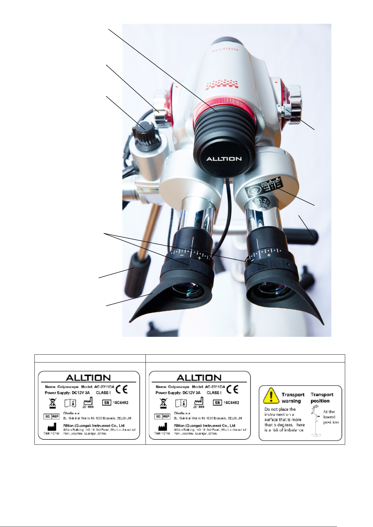
[1] LED Bulb cover
[2] Diopter knobs
[3] Three-step Magnification Knob
[5] Fine Height Adjustment Handle
[6] Fine Focus Handle
[11] Green Filter Knob
[12] Rheostat Knob
[13] These circles give you the
millimeter size at the tissue site
according to the magnification
you’re using.
[14] Eye shields help block external
light
5

Featuring LED Light Source
1 2 3 4 5
7
10
8
9
12
Three-Step Colposcope(Upright Stand)
3.2
* Lasts longer
* Cool to the touch
[1] LED Bulb cover
[2] Diopter knobs
[3] Three-step Magnification Knob
[4] Head Inclination Knob
[5] Fine Height Adjustment Handle
[7] Gross Height Adjustment and Locking Knob
[8] The Rolling Base, with 5 locking wheels
[9] On/Off Switch and Power Indicator Light
[10] Upright Stand
[12] Rheostat Knob
6

AC-2311 (Rolling Base) Label
AC-2311 (Tilting Base) Label
[1] LED Bulb cover
[2] Diopter knobs
[3] Three-step Magnification Knob
[5] Fine Height Adjustment Handle
[6] Fine Focus Handle
[11] Green Filter Knob
[12] Rheostat Knob
[13] These circles give you the
millimeter size at the tissue site
according to the magnification
you’re using.
[14] Eye shields help block external light
7
Upright Stand
L Stand
3.3 Indications for Use
The ALLTION C
olposcope is a device designed for viewing of the tissues of the
vagina and cervix by a telescopic system located outside of the vagina. A
colposcope is used to diagnose and examined abnormalities of the vagina and
cervix.
3.4 Features
* Total magnification 3.75X, 7.5X, 15X for 3-step models and 7.5X for single
magnification models
* 300mm focal length
* Field of View: 79mm, 39mm, 19mm dia. For 3-step magnification models and
39mm for single
magnification models
* Depth of Field: 4.5mm, 1.13mm, 0.76mm for 3-step magnification models and
1.13mm for single
magnification models
* Light intensity: >25,000 LUX
* Individually adjustable eyepiece 16.7X
* The two built-in circles of right eyepieces can measure the size of the problem.
* Built-in rheostat for brightness adjustment
* User-selectable built-in green filter for enhanced contrast
* LED bulb is easily changeable.
* Working Height: 950mm to 1250mm
(AC-2000DA: 950mm to 1150mm)
* Fine focus adjustment Handles
* Two(Gross/Fine)height adjustment Handles
* Upright Stand Colposcope has been installed before leaving the factory, it can be
used as long as turn on the power/ Please install the head of L Stand Colposcope
before turning on the power and using it .
* Main Power Supply:
DC12/3A (Adapter:Input:AC100-240V 50/60Hz, Output:DC12V 3A)
* CMOS Sensor: 1/2.8 in CMOS imaging sensor
* HDMI Output Image: clear image,
resolution ratio is1920x1080, the fastest
speed of preview can reach 60 FPS
4 Installation of Colposcope
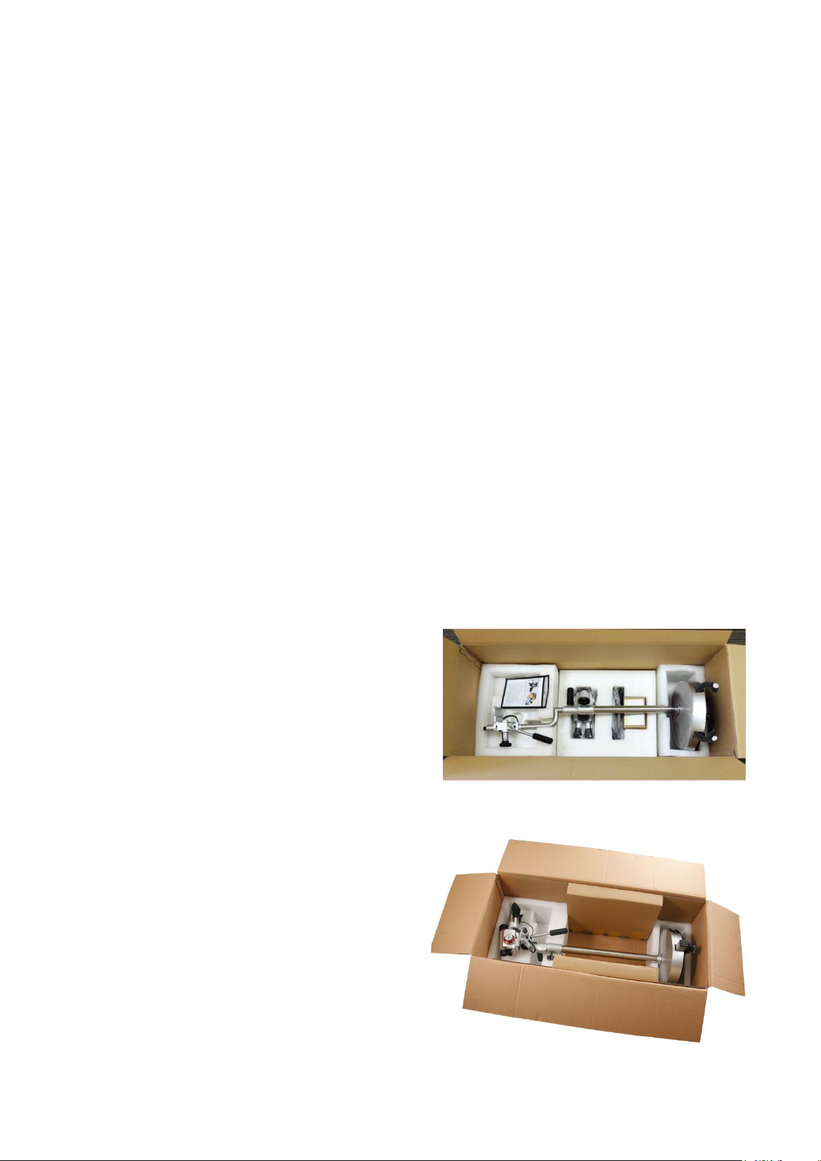
4.1 Contents of Box
After removing the main packing materials, you
will find the colposcope components located as
shown below:
*
1 Colposcope (Upright Stand)
* 1 Colposcope stand and 1 Colposcope
head(L Stand)
*
Power adaptor
1
*
lug (US, UK, EU, AUS)
1 P
* 1 Plastic Dust Cover
* 1 Instructions for use
* 1 Cloth
* 1 Pair Eye shields
* 1 HDMI transmission line (only the
colposcope with CCD camera have it)
4.2
Removing the Colposcope From the
Box
8
5B
IPD
Tilting Base
The Colposcope comes with a two years warranty
with free repairs (Shipping not included). Please
keep the box and the protective foam for at least
two years in case the production need to be
returned to ALLTION company for any warranty
repairs. Otherwise we will charge a fee for
sending a new box.
* The box must be placed in the up position
according to the arrows that are printed on the
outer box during being carried and unpacked.
* Remove top protective material.
* Grasp the Colposcope at the center post (A cutout in the foam for your hands is provided.)
and lift the Colposcope straight out of the protective material. Note: When removing the
instrument out of the protective foam, remove with care to prevent the instrument from being
damaged.
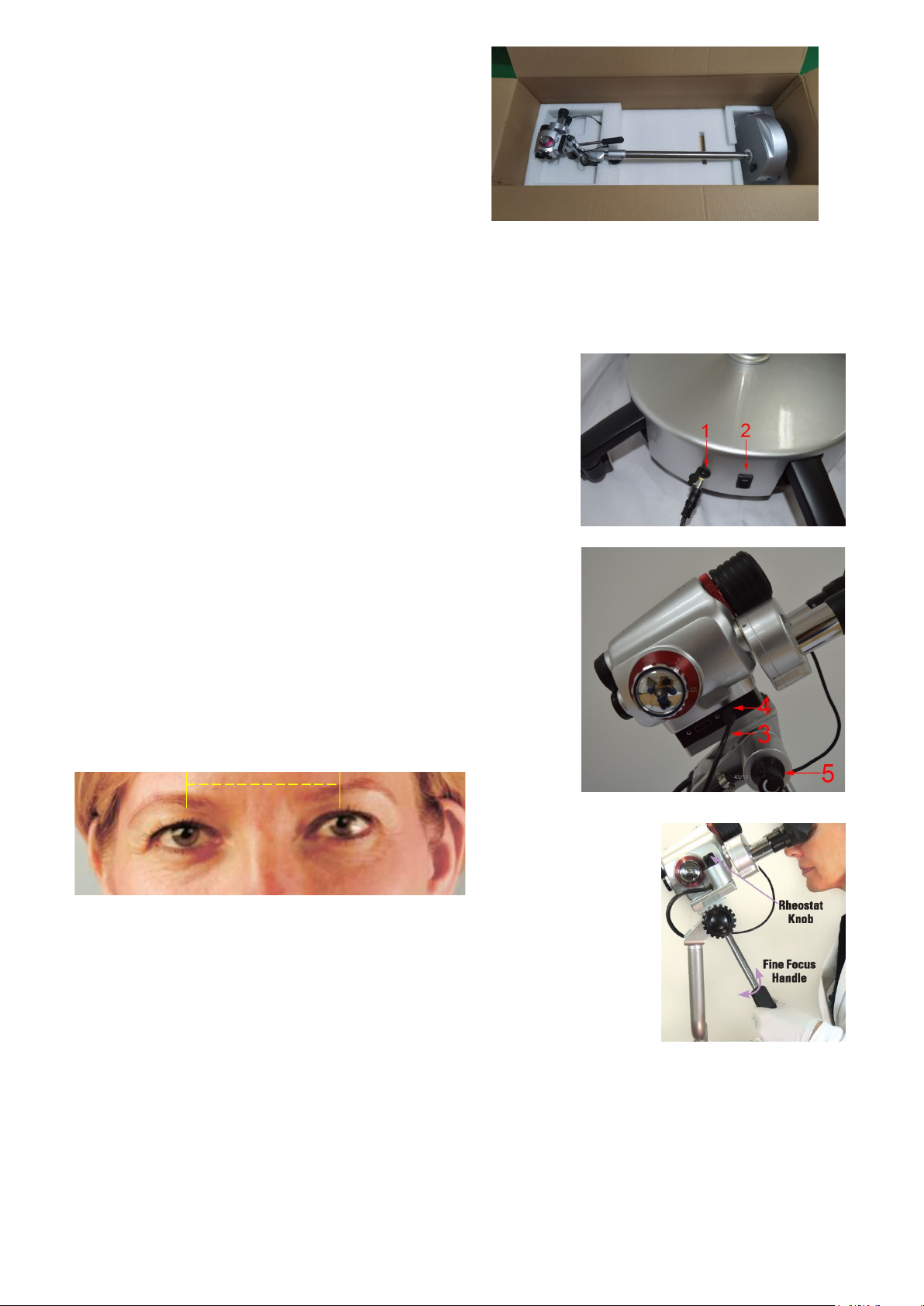
4.3 Setting Up the Colposcope
A. Remove the power
B. Insert the
the base(1).
C. Insert the other end of the
Connect the power line of stand(3) to the Camera socket(4).
D.
E. When the instrument need to be turned on .Press the on
button(2) then the light of power indicator come up .
F. Important: Rotate the Rheostat Knob(5) to turn on the
Viewing Light. (5B.)
G. When the instrument need to be turned off. Press the off
button then the light of power indicator light of the light of
power indicator go out.
adapter
adapter
into the plug located at the back end of
from the shipping box.
adapter
into the wall socket.
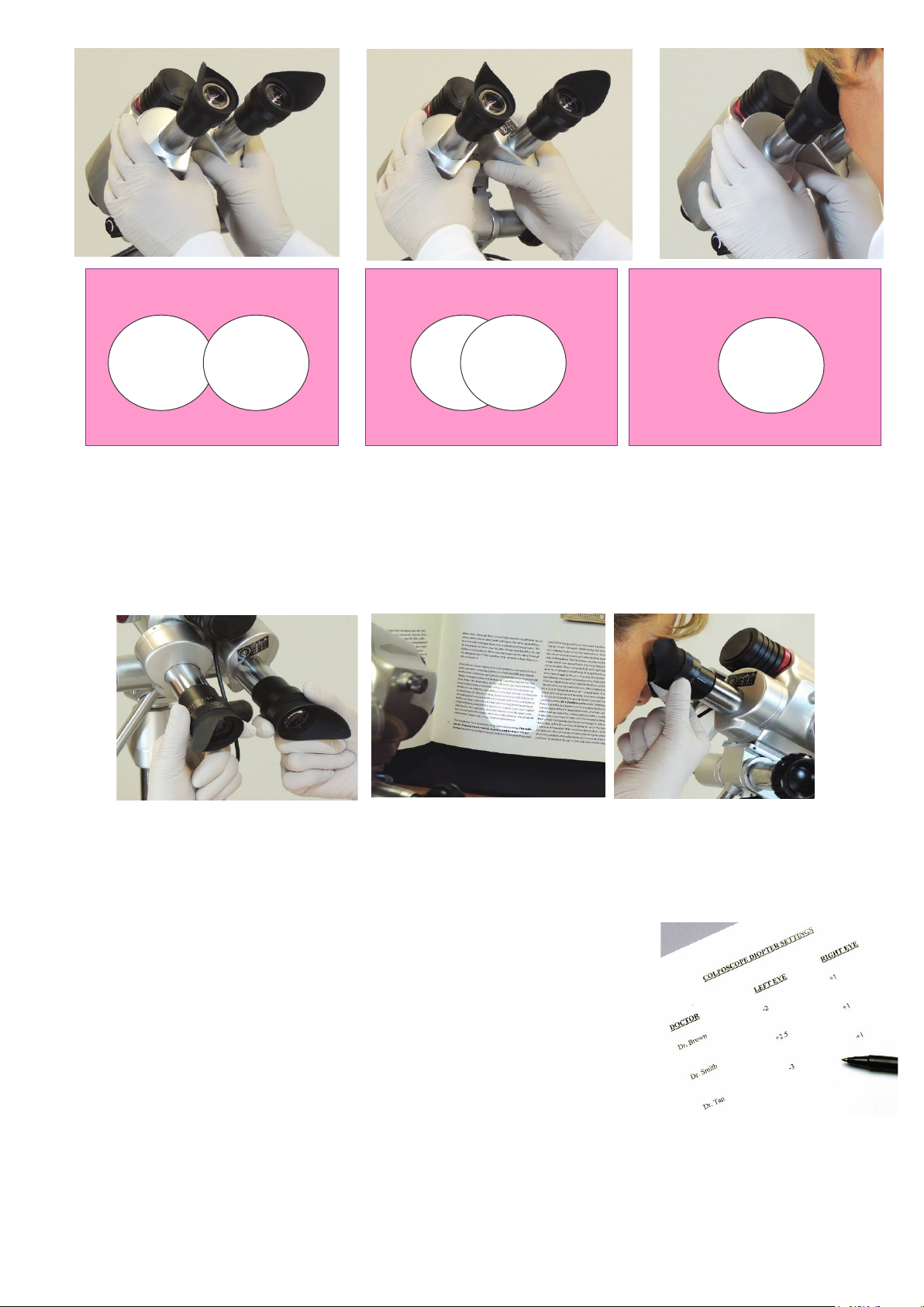
5 Adjustment of the Eyepieces
You must adjust the eyepieces to your interpupillary distance
(IPD).
IPD means the distance between your eyes.
5.1 To Adjust the IPD (5C)
A. Turn on power by pressing the switch on the base.
B. Turn the black Rheostat Knob on the left to adjust the light
intensity.
Light will project from upper part of the Colposcope.
C. Gently place your eyes against the black rubber eyepieces.
Grasp the metal housing with both hands.
Gently rotate the barrels together or apart.
D. A singular circular image should be seen through both eyepieces.
This adjustment is similar to adjusting the eyepieces of binoculars.
9
5C
5C
5C
Lenses Before Adjustment
Lenses During Adjustment
Lenses Adjusted
5D
5D
5D
6A
6C
6D and 6E
6F
6 Adjustment of the Diopter Knobs
A.
Set the Diopter Knobs
B. Turn the colposcope on, place your eyes against the eyepieces, and focus the colposcope on a
fixed object until that object appears clear and sharp.
C. It is recommended to focus on letters such as a book or a magazine. Do not focus on an object
like a piece of fruit.
D. Close your right eye. With your left hand, rotate the Diopter Knob until the object is clear and
sharp for your left eye. Note: The Diopter allows you to adjust for plus and minus vision
corrections.
E. Then close your left eye. Rotate the right diopter knob with right hand
until the object is clear and sharp for your right eye. Note: The Diopter
allows you to adjust for plus and minus vision corrections.
F. It is important to keep a record of the adjustments on the
Diopters for both your left and right eyes. Since most offices have
multiple people using the Colposcope, the eyepieces will be
different when someone else wants to use it. By remembering
your diopter settings, clarity can be achieved by simply moving the diopters to your
setting when you are ready to use the Colposcope. This avoids you going through steps
A–E each time.
at
zero.
10

7C
G. You will see two measuring circles through the lens. Since your Colposcope has three different
magnifications, the measurement at the tissue site will vary according to the magnification you’re
using. The reference chart gives you the correct size per magnification change.
Note: There is
a chart on the right metal housing.
7 Colposcope Instructions for Use
The following briefly describes using the
Colposcope with a patient. It is
recommended that you practice using the
Colposcope to familiarize your- self with all of
the features it has to offer.
A. Let patient in a supine position.Your
Colposcope should be placed so that the
head of the scope is 300mm from the area
you wish to view, with the post to as near
vertical as possible. Rotate the Gross Height
Adjustment and Locking Knob to loosen it
and move the inner post up or down. Tighten
the knob to lock the inner post in place.
B. In a sitting position, place your eyes
against the eyepiece. Adjust for pupillary
distance and make sure that you set your
correct diopter reading. Place your right
hand on the Fine Height Adjustment Handle
and your left hand on the Fine Focus Handle. Note: Do
not try to focus with Fine Focus .
C. With your hand on the Fine Height Adjustment
Handle, slowly push or pull the Colposcope, until the
field comes into view.
D. Adjust the Fine Focus Controls to provide clear,
magnified views of the area to be examined. Rotate
your left hand on the Fine Focus Handle which will
finely move the optics towards or away from the object
that you wish to view. Also, rotate your right hand which
is on the Fine Height Adjustment Handle up or down to
raise or lower the optics. Adjust light intensity rheostat
as needed by turning the black Rheostat Knob. Turn
the silver Green Filter Knob for optimum assessment of
affected area.
Note: Both the black Rheostat Knob and the silver
Green Filter Knob are conveniently located on the
11

8E. Pull the Fine Height
justment Handle
8F. Push the Fine Focus Handle
8D. Twist the Fine Height
the Gross Height Adjustment
8C
Colposcope head, thus allowing the user complete control without looking up from the eyepieces.
E. The Colposcope head may be tightened or loosened according to your preference by turning the
Head Inclination Adjusting Knob.
Note on all photos
All 1 step colposcopes use the same adjustment techniques as
shown on these pages, although models shown may differ.
8 Selecting Your Preferred Level of Magnification
The ALLTION offers you the advantage of
magnification during a colposcopic examination.
A. When viewing the cervix, reach up and rotate the Three-Step
Magnification Knob.
B. Rotate it to your desired magnification(3.75, 7.5, or 15).When
moving from one magnification to another, slight adjustments
in the fine focusing mechanism might be necessary.
C. Turn the Fine Focus Handle.
If patient is not centered, you can move the Colposcope head in
multiple directions to change your field of vision. See photos D–F.
increasing or decreasing
Adjustment Handle to move the
head up or down slightly. Use
Adjustment Handle backward
and to the right, or Push the Fine
Height Ad
forward and to the left.
down and forward, or pull it up and
backward.
Knob to make larger height
adjustments.
12

10B
9 Integrated Video Camera
An integrated video camera (1 CCD) is available in specific
models.
It is very convenient for the doctors to communicate with the
patient by this device.
1.CCD camera power: connect the black wire(3) from the bracket
to the camera socket in the head.
2.Video Output:Connect the attached HDMI line to the HDMI port
(1) in the head, and then connect the other end of attached HDMI
line to the HDMI port of TV or Monitor AV adapter.
3. Internal CCD Camera: The images from integrated video
camera can be inputted into a monitor or a TV set directly. Or it
can be inputted into a computer by image collection with USB 3.0
HDMI adapter or stored into a hard disk recorder
10 Storage and Precautions
A. For storage, the instrument should be placed in a clean, dry
environment with stable temperatures to extend the life of the
components and ensure longevity of the instrument.
B. Please cover the Colposcope with the plastic dust cover that is
included with this instrument. This will keep the optics and
components relatively dust free.
C. When storing or carrying the instrument, adjust the instrument to
the lowest position. This will help ensure that if it is inadvertently hit, it
will resist tipping over.
11 1Moving the Colposcope
*
Rotate the Gross Height Adjustment and Locking Knob to move
the post to a comfortable position.
*
Tighten the Gross Height Adjustment and Locking Knob.
*
Place your foot between the wheels at the front end of the base.
*
With your hand on the Fine Height Adjustment Handle,
pull forward and roll across the floor.
13

The AC-2000 is intended for use in the electromagnetic environment specified below. The customer
or the user of the AC-2000 should assure that it is used in such an environment.
3
Emissions test
Compliance
Electromagnetic environment - guidance
F energy only for its internal function.
ts RF emissions are very low and are not likely
RF emissions
CISPR11
Harmonic
IEC 61000-3-2
Voltage fluctuations
IEC 61000-3-3
The AC-2000 is intended for use in the electromagnetic environment specified below. The customer or the
user of the AC-2000 should assure that it is used in such an environment.
IEC 60601
test level
Electromagnetic environment guidance
Mains power quality should be that of a
environment.
0 % UT ; 0.5 cycle
1 cycle
and
0 % UT ; 0.5 cycle
Mains power quality should be that of a
typical commercial or hospital
operation
during power mains interruptions, it is
be
powered from an uninterruptible power
12 Technical Data Continued
12.1 Guidance and Manufacturer´s Declaration – electromagnetic Emission – for
all Equipment and Systems
1 Guidance and manufacturer´s declaration – electromagnetic emission
2
RF emissions
4
CISPR11
5
emissions
6
/
7
flicker emissions
Group 1
Class A
Class A
Complies
12.2 Guidance and Manufacturer's Declaration – electromagnetic Immunity – for
all Equipment and Systems
Guidance and manufacturer´s declaration – electromagnetic immunity
Immunity test
The AC-2000 uses R
Therefore, i
to cause any interference in nearby electronic equipment.
The AC-2000 is suitable for use in all
establishments, including domestic establishments and tho
se directly
connected to the public low-voltage power supply networ
k that
supplies buildings used for domestic purposes.
Compliance level
Electrostatic
discharge (ESD)
IEC 61000-4-2
Electrostatic
transient / burst
IEC 61000-4-4
Surge
IEC 61000-4-5
Voltage dips, short
interruptions and
voltage variations
on power supply
input lines
IEC 61000-4-11
± 8 kV contact
± 15 kV air
± 2 kV for power
supply lines
± 1 kV differential
mode
At 0°,45°,90°,135°,
180°,225°,270°and
315°
0 % U
T;
± 8 kV contact
± 15 kV air
± 2 kV for power
supply lines
± 1 kV differential
mode
At 0°,45°,90°,135°,
180°,225°,270°and
315°
0 % U
1 cycle and
T;
14
Floors should be wood, concrete or
ceramic tile. If floors are covered with
synthetic material, the relative humidity
should be at least 30 %.
Mains power quality should be that of a
typical commercial or hospital
environment.
typical commercial or hospital
environment. If the user of the
AC-2000 requires continued
recommended that the AC-2000

25/30
250/300
70 % U
25/30
250/300
supply or a battery.
Power frequency
IEC 61000-4-8
Power frequency magnetic fields should
levels characteristic of a typical
location in a typical commercial or
hospital environment.
The AC-2000 is intended for use in the electromagnetic environment specified below. The customer or the
level
level
between 0,15 MHz
150 kHz to 80
V in ISM
between 0,15
80 MHz to 2.7
Portable and mobile RF communications
any
2000, including cables, than
the recommended separation distance
calculated from the equation applicable to the
P
V
d ]
5.3
[1=
P
E
d ]
5
.3
[1=
P
E
d ]
7
[1=
is the maximum output power rating
of the transmitter in watts (W) according to the
is the
distance in metres
RF transmitters, as
determined by an electromagnetic site
should be less than the compliance
T;
70 % U
cycles
Single phase: at 0°
0 % UT;
cycle
T;
cycles
Single phase: at 0°
0 % UT;
cycle
(50/60 Hz)
magnetic field
NOTE U
3 A/m 3 A/m
is the a. c. mains voltage prior to application of the test level.
T
12.3 Guidance and Manufacturer´s Declaration – electromagnetic Immunity – for
Equipment and Systems that are not Life-supporting
Guidance and manufacturer´s declaration – electromagnetic immunity
user of the AC-2000 should assure that it is used in such an environment.
Immunity test
Conducted RF
IEC 61000-4-6
Radiated RF
IEC 61000-4-3
IEC 60601 test
3 V rms
150 kHz to 80 MHz
6 V in ISM bands
and
80 MHz
3 V/m
80 MHz to 2.7 GHz
Compliance
3 V rms
MHz
6
bands
MHz and
80 MHz
3 V/m
GHz
be at
Electromagnetic environment - guidance
equipment should be used no closer to
part of the AC-
frequency of the transmitter.
Recommended separation distance
80 MHz to 800 MHz
800 MHz to 2.7 GHz
where p
transmitter manufacturer and d
recommended separation
b
(m).
15
Field strengths from fixed
survey,
a

level in each frequency range.
Interference may occur in the vicinity of
NOTE 2 These guidelines may not apply in all situations. Electromagnetic is affected by absorption and
a
Field strengths from fixed transmitters, such as base stations for radio (cellular/cordless) telephones
and land mobile radios, amateur radio, AM and FM radio broadcast and TV broadcast cannot be predicted
rs, an
electromagnetic site survey should be considered. If the measured field strength in the location in which the
e observed to
rformance is observed, additional measures may be necessary, such
equipment marked with the following symbol:
NOTE 1 At 80 MHz and 800 MHz, the higher frequency range applies.
reflection from structures, objects and people.
theoretically with accuracy. To assess the electromagnetic environment due to fixed RF transmitte
AC-2000 is used exceeds the applicable RF compliance level above, The AC-2000 should b
verify normal operation. If abnormal pe
as reorienting or relocating the AC-2000.
b
Over the frequency range 150 kHz to 80 MHz, field strengths should be less than 3V/m.
16

Recommended separation distances between
portable and mobile RF communications equipment and the AC-2000
r use in an electromagnetic environment in which radiated RF disturbances are
2000 can help prevent electromagnetic interference by
equipment
as recommended below, according to the maximum output power of the
P
V
d ]
5.3
[1=
P
E
d ]
5.3
[1=
P
E
d
]
7
[
1
=
For transmitters rated at a maximum output power not listed above the recommended separation distance d
in metres (m) can be estimated using the equation applicable to the frequency of the transmitter, where P is
12.4 Recommended Separation Distances between Portable and Mobile RF
Communications Equipment and the Equipment or System-for Equipment and
Systems that are not Life-Supporting
The AC-2000 is intended fo
controlled. The customer or the user of the AC-
maintaining a minimum distance between portable and mobile RF communications
(transmitters) and the AC-2000
communications equipment
Separation distance according to frequency of transmitterm
Rated maximum
output of
transmitter
W
150 kHz to 80 MHz
80 MHz to 800 MHz
800 MHz to 2.7 GHz
0.01 0.12 0.12 0.23
0.1 0.38 0.38 0.73
1 1.2 1.2 2.3
10 3.8 3.8 7.3
100 12 12 23
the maximum output power rating of the transmitter in watts (W) according to the transmitter manufacturer.
NOTE 1 At 80 MHz and 800 MHz, the separation distance for the higher frequency range
applies.
NOTE 2 These guidelines may not apply in all situations. Electromagnetic propagation is
affected by absorption and reflection from structures, objects and people.
17

Trouble
Check
Possible reason
Remedy
Illumination
failure
Power switch indicator Not light
Main power broken
Contact a local electrician
Never switch on the power
switch.
Switch on the power switch.
The adaptor has been m
Replacing the adaptor
Power switch indicator light
Illuminate brightness adjusting
button is in low position
Adjust the button to the high
position
The LED has burnt.
Contact the After
service Dept.
LED1 and LED2 on the circuit
board is
The LED has burnt or
connection line loosening
Contact the After
service Dept.
LED1 and LED2 on the circuit
board is light(blue)
Use the diode gear of the
multimeter to touch the po
and negative of the LED supply
line.
LED light
damage
The LED not light: the circuit
board and the LED are
damaged
Contact the After
service Dept.
Dimming fault
Adjust the dimming knob, the
brightness of the LED is
constant, or the brightness of the
LED varies only in a darker range
Dimming potentiometer
damage or connection line
loosening
Contact the After
service Dept.
Observe the LED3 on the circuit
board:
Dimming potentiometer
damage or conne
loosening
Contact the After
service
Observe the LED3 on the circuit
board: not
the circuit board is damaged
Contact the After
service Dept.
Colposcope
Head Keeps
Turning
The damping is not adjusted
well or unlocked
Ti
Adjustment and locking
Knob
13 Troubleshooting
-down
elted
-sales
-sales
light (blue)
shiny: circuit board
sitive
-sales
-sales
-sales
Dept.
-sales
light shiny
light
(green)
ction line
ghten Gross Height
18

14 Information about disinfection for Alltion LED Colposcope
The cleaning of the surface of Colposcope
You can wipe the colposcope with 75% medicinal alcohol on a clean cloth, and you can use
the disposable alcohol pads, usually used to clean skin. Care must be taken not to put the alcohol
on any lenses, whether that be the lenses the doctor looks through or the lenses towards the
patient. Should not ues corrosive or scrub cleanser to clean the Colposcope
The cleaning of the surface of Optical Lens
The bloodstain or other dirt on the lens can be cleaned with lens paper or cotton wool that’s
with distilled water and a little of household detergent. The remaining trace can be cleaned with
lens paper or cotton wool that’s with 95% alcohol (wipe from centre to outside by spiral slightly).
The dust on the lens can be cleaned with blown ballon or whisk pen. Should not ues corrosive or
scrub cleanser to clean the lens.
The sterilize for the Colposcope
All disinfectant cover can sterilize by pressure sterilizing cooker. Recommend temperature
and time as follow:
(1) Disinfect it for 10 min when the temperature is 120
(2) Disinfect it for 5 min when the temperature is 134
Attention: The dirt on the lens of Colposcope should be cleaned as soon as possible after
using the colposcope. Otherwise it will be more difficult to clean when the dirt become hard and
dry. You’d better clean and disinfect the colposcope frequently.
℃
℃
15 Disposal
The product must not be disposed of along with other domestic waste. The users must dispose of
this equipment by bringing it to a specific recycling point for electric and electronic equipment.
16 GIMA WARRANTY TERMS
The Gima 12-month standard B2B warranty applies.
19
 Loading...