

SPECIFICATIONS
Motor 1-3/4 Working HP
Elec tric al 120 V~, 14 Amps, 3450 RPM, Single Phase, 60 Hz
Power Cord 3 prong grounded 14 AWG X 3C
Air Outlet Fitting 1/4” NPT barbed
Drive Type Direct
Pump Stage Single
Air Tank Size 4 Gal.
Pressure Range Pressure Switch On at 80 PSI; Pressure Switch Off at 115 PSI
Air Delivery 4.2 SCFM at 90 PSI; 5.2 SCFM at 40 PSI
Pressure Disconnect Automatically releases pressure if overloaded to 120 PSI
Oil Requirement Standard non-detergent 30 weight compressor or motor oil
Weight 51 Lbs.
Page 2
Note: When using extension cords (not included) - To avoid circuit breaker and voltage
drop problems, we recommend using only 12 gauge x 50 foot extension cords
FEATURES OF THIS COMPRESSOR
1. This small, portable compressor is ideal for use in shops with limited storage space.
2. 80-115 PSI operating range is ideal for most shop uses including air tools, spraying,
tire LQÀDWLRQ air cleaning, etc.
3. Pressure switch maintains correct operating pressure at all times.
4. Pressure gauge gives continuous, real-time readout of current pressure delivery.
5. Maximum pressure disconnect safety valve prevents over-pressurization of tank.
6. Delivers enough air for continuous use in most applications.
7. Sturdy construction will deliver years of satisfactory service.
8. Your compressor is fully assembled when you receive it.
Warning: Fill compressor with oil before using; running with NO or LOW
OIL voids warranty. Optimal oil tank capacity is 7.8 ounces.
SAVE THIS MANUAL
You will need the manual for the safety warnings and cautions, assembly instructions, operating procedures, maintenance procedures, trouble shooting, parts list, and diagram. Keep
your invoice with this manual. Write the invoice number on the inside of the front cover.
Keep both this manual and your invoice in a safe, dry place for future reference.
NOTICE
The Warnings, Cautions, and Instructions discussed in this instruction manual
cannot cover all possible conditions and situations that may occur. It must be
understood by the operator that common sense and caution are factors which
cannot be built into this product, but must be supplied by the operator.
APC4026
4 Gallon Dishing Tank
AIR COMPRESSOR
Owner’s Manual
Please read and save these instructions.
www.allpoweramerica.com
&4#/3#12'-,1-0,##"1#04'!#
"-,-20#230,2-12-0#
SAFETY WARNING & CAUTIONS
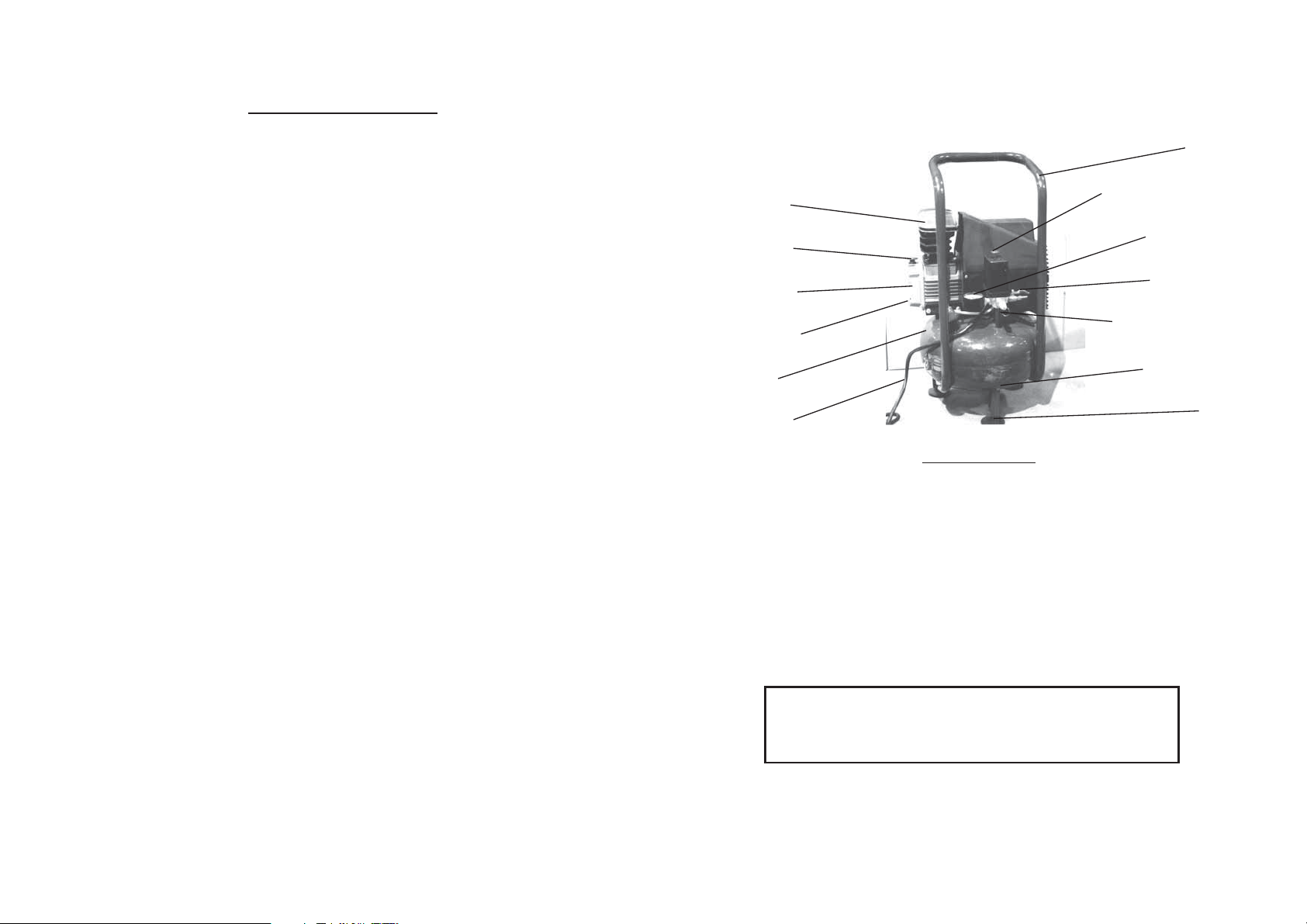
Handle
ON / OFF Power Switch
Pressure Gauge
Air Flow Valve
Pressure Release Valve
Tank Drain Valve
Foot
Compressor
Oil Dipstick
Oil Reservoir
Oil Drain Plug
Air Tank
Power Cord
Page 4
ELECTRICAL SET UP
Your compressor has a grounded, three-prong plug. If using an extension cord, it must be a
three-prong type. You must connect to a three-prong receptacles only. The third prong is for grounding;
do not remove or disable the third prong, as this will create an unsafe condition.
Common household current is 110-120 Volts. As long as your compressoris rated from 110-120
Volts, there will be no complications in using power from a household receptacle. Never try to plug a
tool designed for 110-120 Volts into a 220-240 Volt receptacle. 220V plugs and outlets are shaped
differently to prevent this.
Only use rounded jacket extension cords, preferably listed by Underwriter’s Laboratories
(UL).
Make sure the cord is rated for outdoor use, even if your application is indoors. Outdoor use
cords have the letters “WA” on the cord jacket.
The extension cord must have a minimum wire size depending on the amperage of the tool
and the length of the extension cord. The size is VLJQL¿HG by its AWG (American Wire Gauge) rating;
the smaller the gauge, the greater the cable’s capacity.
Note: When using extension cords - To avoid circuit breaker and
voltage drop problems when using extension cords, we recommend
using only 12 gauge x 50 foot extension cords .
WARNING: When using pneumatic equipment, basic safety precautions should always be followed
to reduce the risk of personal injury and hazards.
READ ALL INSTRUCTIONS BEFORE USING THIS TOOL!
1. KEEP WORK AREA CLEAN. Cluttered areas invite injuries.
2. OBSERVE WORK AREA CONDITIONS. Do not use tools in damp, wet, or poorly lit locations.
Don’t expose to rain. Keep work area well lit. Do not use electrically powered air compressors in
the presence of ÀDPPDEOH gases or liquids.
3. KEEP CHILDREN AWAY. Children must never be allowed in the work area. Do not let them handle
machines, tools, or hoses.
4. STORE IDLE EQUIPMENT. When not in use, tools must be locked up in a dry location to inhibit
rust. Always lock up tools and keep out of reach of children.
5. DO NOT FORCE THE TOOL. It will do the job better and more safely at the rate for which it was
intended. Do not use inappropriate attachments in an attempt to exceed the tool’s capacities.
6. USE THE RIGHT TOOL FOR THE JOB. Do not attempt to force a small tool or attachment to do
the work of a larger industrial tool. Do not use a tool for a purpose for which it was not intended.
7. DRESS PROPERLY. Do not wear loose clothing or jewelry as they can be caught in moving parts.
Nonskid footwear is recommended. Wear restrictive hair covering to contain long hair.
8. USE EYE AND EAR PROTECTION.Always wear ANSI-approved chemical splash goggles when
working with chemicals. Always wear ANSI-approved impact safety goggles at other times. Wear
a full face shield if you are producing metal ¿OLQJV or wood chips. Wear an ANSI-approved dust
mask or respirator when working around metal, wood, and chemical dusts and mists.
9. DO NOT OVERREACH. Keep proper footing and balance at all times. Do not reach over or across
running machines.
10. MAINTAIN TOOLS WITH CARE. Keep tools sharp and clean for better and safer performance.
Follow instructions for lubricating and changing accessories. Inspect hydraulic lines and seals
periodically and, if damaged, have them repaired by an authorized technician. Inspect all hoses
for leaks prior to use. The handles must be kept clean, dry, and free from oil and grease at all
times.
11. REMOVE ADJUSTING KEYS AND WRENCHES. Make it a habit to check that keys and adjusting
wrenches are removed from the tool or machine work surface before plugging it in.
12. STAY ALERT. Watch what you are doing, use common sense. Do not operate any tool when you are
tired.
13. CHECK DAMAGED PARTS. Before using any tool, any part that appears damaged should be
carefully checked to determine that it will operate properly and perform its intended function. Check
for alignment and binding of moving parts; any broken parts or mounting ¿[WXUHV and any other
condition that may affect proper operation. Any part that is damaged should be properly repaired
or replaced by a TXDOL¿HG technician. Do not use the tool if any switch does not turn on and off
properly.
14. REPLACEMENT PARTS AND ACCESSORIES. When servicing, use only identical replacement
parts. Use of any other parts will void the warranty. Only use accessories intended for use with
this tool. Approved accessories are available from Harbor Freight Tools.
15. DO NOTOPERATETOOL IF UNDER THE INFLUENCE OF ALCOHOL OR DRUGS. Read warning
labels on prescriptions to determine if your judgment or UHÀH[HV are impaired while taking drugs.
If there is any doubt, do not operate the tool.
16. MAKE SURE ALL EQUIPMENT IS RATED TO THE APPROPRIATE CAPACITY. Do not attempt
any operations or hook up any equipment that would not meet the rated capacities of this tool.
Page 3
Your compressor is fully assembled when you receive it. Before using it, perform the
Page 6
OPERATION
1. Before each use, perform the following checks:
Check to be sure the drain valve at the bottom
of the tank is closed. Check to be sure the oil
level is between the marks on the dip stick. Be
sure the safety pressure release valve has not
been damaged, and is functional.
2. Turn the Air Flow Valve to the OFF position. In
the OFF position, the red handle is across (perpendicular to) the line of the air hose ¿WWLQJ
In the ON position, the red handle is parallel with
the line of the air hose ¿WWLQJ
3. Turn ON the compressor, by pulling the Red ON/
OFF Switch up. Turn OFF the compressor by
pushing the ON /OFF switch down.
4. Allow the compressor to build up at least 80 PSI
as indicated on the pressure gauge.
5. While the compressor is building up pressure,
attach the hoses, ¿WWLQJV and air tools you will use.
6. When the pressure has reached 80 PSI; open the air ÀRZ valve to allow the hoses and tools
to become pressurized. Check for any VLJQL¿FDQW air leaks, and check the operation of your
tool.
7. As long as the power switch is pulled ON, the operation of the compressor is automatic, controlled by an internal pressure switch. The compressor will turn on automatically when the
pressure drops to 80 PSI, and will turn off when the pressure reaches 115 PSI. Warning: This
;dednemmocertoneraslevelerusserpehtotsegnahctubelbatsujdasihctiwserusserp
any change to the automatic ON/OFF pressure levels will cause additional stress on the
motor which may result in shortened motor life.
NOTE: If it is necessary to quickly depressurize the air compressor
,
First: Turn it off by pushing the ON / OFF switch down.
Then: Pull out on the ring on the pressure release valve to quickly release stored pressure.
WARNING
1. To reduce the risk of ¿UH or explosion, never spray ÀDPPDEOH liquids in a FRQ¿QHG area. Always
operate the compressor in a well ventilated area. Do not smoke while spraying. Do not spray
where sparks or ÀDPH are present. Keep the compressor as far away from the spray area as
possible.
2. Never directly inhale the compressed air produced by the compressor. It is not suitable for
breathing purposes.
3. Never weld on the tank of this compressor. Welding of the tank could affect tank strength and
result in an extremely hazardous condition.
4. To avoid the potential for electric shock, never use this compressor outdoors when it is raining,
and never use the compressor on a wet surface.
5. Never point any nozzle or sprayer towards a person or animal.
6. Never work on or make adjustments to the tank when the tank is under pressure.
7. Never service or make adjustments to this product without ¿rst unplugging the electrical
cord.
8. Never place ÀDPPDEOH objects near the compressor. Never spray water or ÀDPPDEOH liquids
toward or near the compressor.
9. Always push the ON/OFF switch down into the OFF position when the unit is not in use.
10. Do not transport the pancake compressor when the tank is under pressure.
11. Only operate in a well-ventilated area which has proper air circulation.
Note: Always use a 120V electrical
source (±10% maximum variation).
Fig. 3. Controls
Pressure Gauge
ON / OFF Switch
Pressure Release Valve
Air Flow Valve
Note: Compressor has a Thermal Overload Switch (#41).<>If Compressor shuts down from overheating
or related problems, turn Compressor OFF and allow it to cool down for 10 minutes. Once cooled, push in
Thermal Overload Switch and restart Compressor.
SET UP & OPERATION
following set up operations.
%HIRUHXVLQJ\RXUFRPSUHVVRUIRUWKH¿UVW
time, check to be sure the oil reservoir is
¿OOHG
Note: Optimal oil tank capacity is 7.8
ounces.
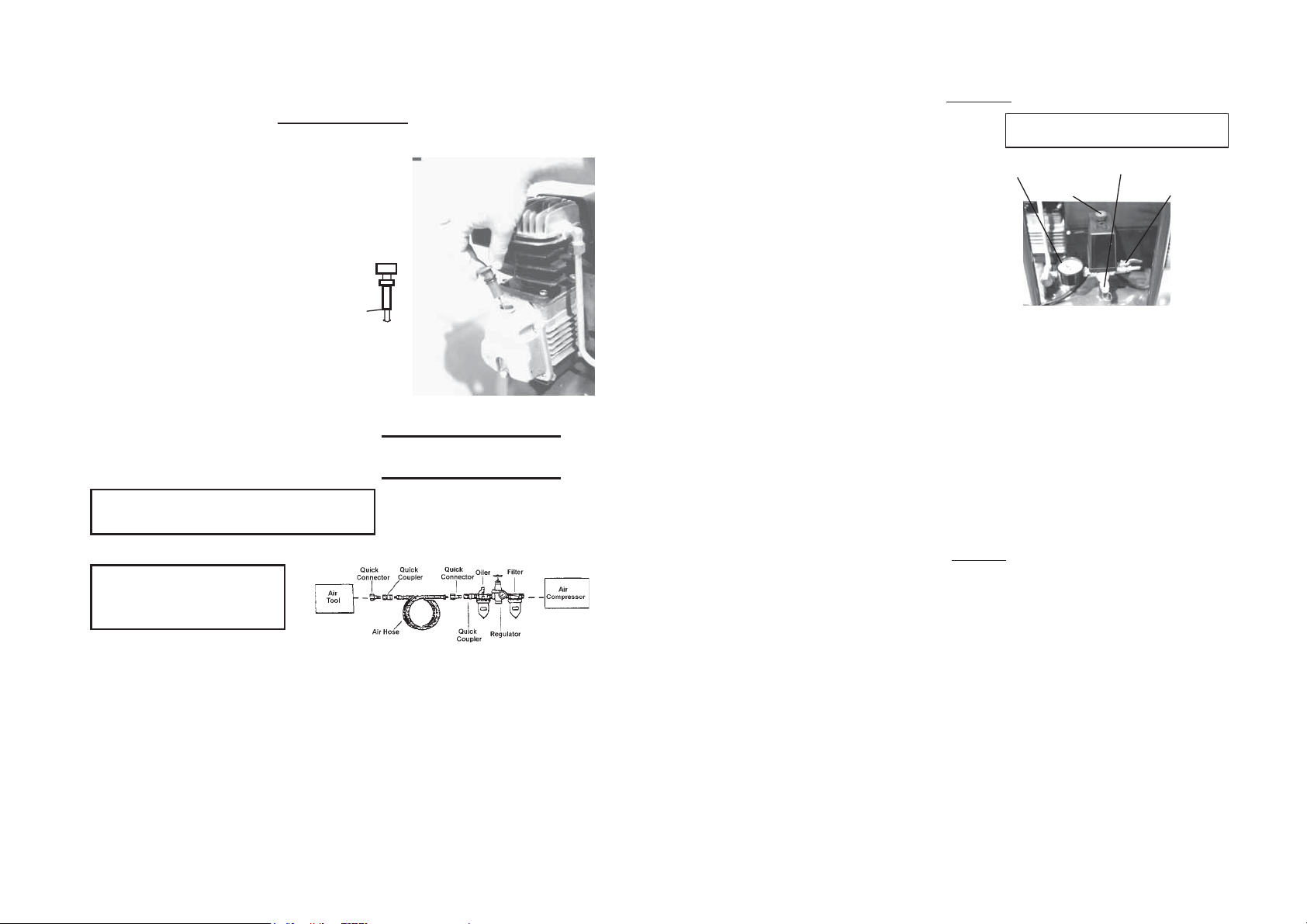
1. Unscrew the threaded Oil Dipstick to
remove it from the oil reservoir.
2. Look at the oil level on the dip stick. The
proper oil level is shown on the illustration to the right.
3. If the oil level is low, add standard,
non-detergent 30-weight non detergent
compressor oil, (use lighter weight
oil for cold weather operation).<>Add
a little at a time, and check the level
before each addition. Do not over¿ll.
If RYHU¿OOHG you can remove the drain
plug to allow oil to drain out.
4. When the oil level is correct, replace the
dipstick.
1H[WFRQQHFW\RXUDLUKRVHV¿OWHUDQG
UHJXODWRUWRWKHFRPSUHVVRrDVLOOXVWUDWHGLQ
)LJXUHEHORw.
Warning: Fill with compressor oil before using;
running with NO or LOW OIL voids warranty.
Warning: Do not remove
factory sealed
Air Flow Valve
(#9A); removal of valve voids
warranty.
1. .teltuoriaehtotesohriaerusserphgihehttcennoC.TPN”4/1siteltuoriadedivorpehT
Note: For easy connection or removal, a quick coupler (included) should be installed
on the end of the outlet (a female and a male coupler are also included to use with the
quick coupler).
2. For best service, you should incorporate an oiler, a regulator, and a ¿OWHU in line; as
shown in the above diagram.
3. Hoses, Couplings, Fittings, Oilers, Regulators, and Filters are all available from All-
Power America.
Oil
Dipstick
Proper
Oil Level
)LJXUH&KHFNLQJWKH2LO/HYHO
Use Pipe Thread Seal tape on all
NOTE:
threaded connections.
Figure 2 — Connecting the Air Compressor
Page 5
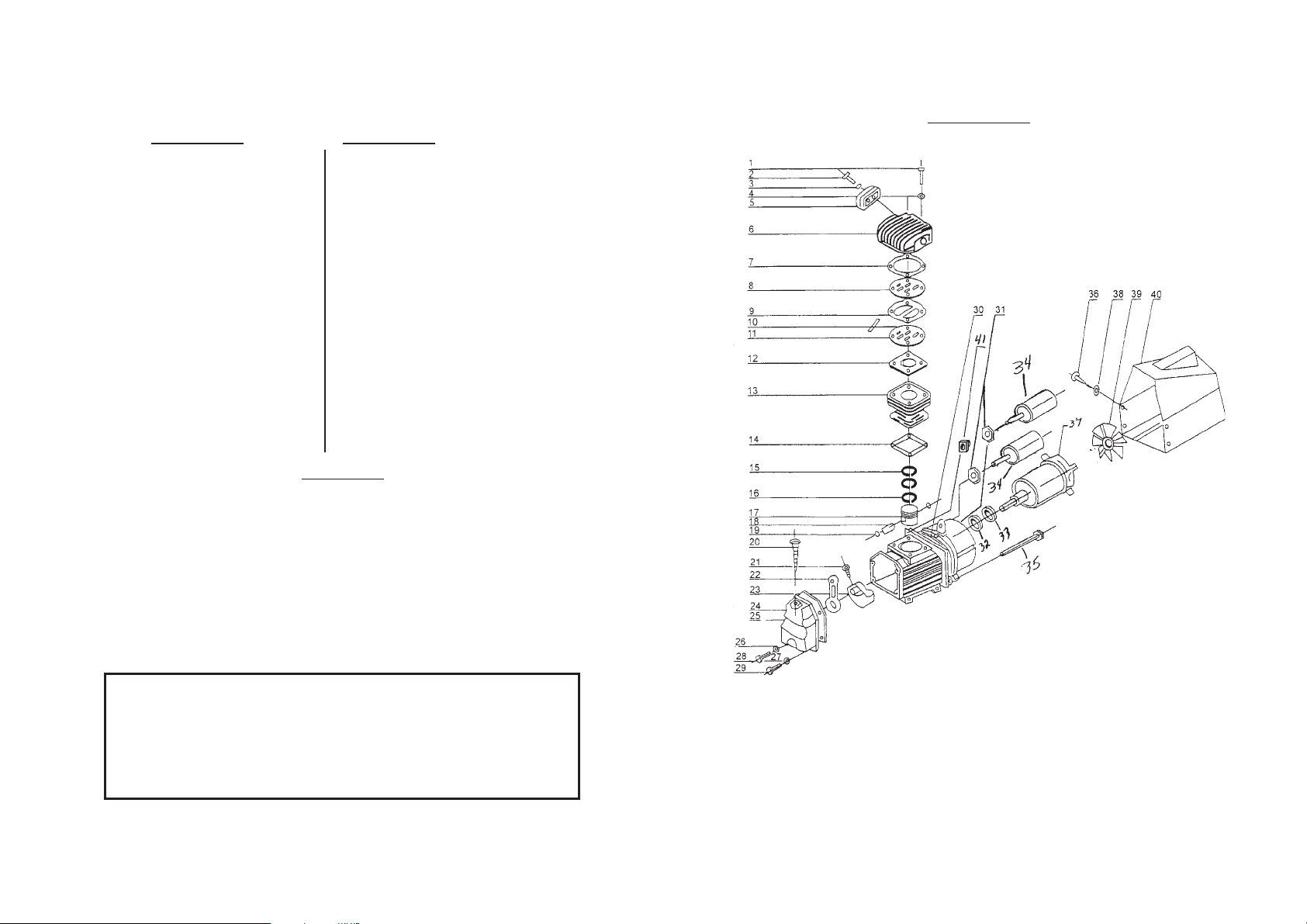
Compressor Assembly
PARTS DIAGRAM
Page 8
NOTE: Part # 7,8,9,10,11,12 are only available as a kit ( Rebuild Kit SKU 27349 )
Part # Description
1 Screw
2 Screw
3 Washer
4 Washer
5 Air Filter
6 Cylinder Case
7 Gasket, Crankshaft Cover
8 Valve Seat
9 Gasket, Valve Seat
10 Valve Plate
11 Valve Seat
12 Gasket, Valve Seat
13 Cylinder
14 Cylinder Gasket
15 Compression Ring
16 Scraping Oil Ring
17 Piston
18 Piston Pin
19 Crankshaft Retainer
20 Oil Stick
21 Screw
Part# Description
22 Connecting Rod
23 Crankshaft
24 Gasket, Front Cover
25 Front Cover
26 Washer
27 Washer
28 Bolt
29 Screw
30 Crankshaft Case
31 Nut
32 Seal Washer
33 Bearing
34 Electric Capacitor
35 Bolt
36 Screw
37 Motor
38 Washer
39 Radiating Fan Wheel
40 Radiating Cover
41 Thermal Switch
1. Check the oil before each use to be sure the level of oil is correct (see illustration on page
MAINTENANCE
the oil level is too low, add oil. If it is too high, drain some oil out by removing the drain
5).<>If
plug.
2. Drain and replace the oil once per year. Replace more often if the compressor is used heavily
or the oil appears dirty
.
3. Check the air ¿OWHU every six months, or more often if compressor is used in a dirty or dusty
environment. Replacement air ¿OWHUV are available from Harbor Freight Tools.
4. Drain the air tank after each use, by turning the drain petcock clockwise to open it. Turn the
petcock counterclockwise to close it. It is a good practice to leave the drain plug open between
uses to ensure that the tank remains dry.
5. Never use ÀDPPDEOH liquids or solvents to clean the compressor. For cleaning, unplug the
unit, and clean with a mild detergent and water. Be carefulnot to introduce water into any electrical
components.
THE MANUFACTURER AND/OR DISTRIBUTOR HAS PROVIDED THE PARTS DIAGRAM IN THIS MANUAL
AS A REFERENCE TOOL ONLY: NEITHER THE MANUFACTURER NOR DISTRIBUTOR MAKES ANY
REPRESENTATION OR WARRANTY OFANY KIND TO THE BUYER THAT HE OR SHE IS QUALIFIED TO MAKE
ANY REPAIRS TO THE PRODUCT OR THAT HE OR SHE IS QUALIFIED TO REPLACE ANY PARTS OF THE
PRODUCT:IN FACT THEMANUFACTURER AND/OR DISTRIBUTOR EXPRESSLY STATES THATALL REPAIRS
AND PARTS REPLACEMENTS SHOULD BE UNDERTAKEN BY CERTIFIED AND LICENSED TECHNICIANS
AND NOT BY THE BUYER. THE BUYER ASSUMES ALL RISK AND LIABILITY ARISING OUT OF HIS OR HER
REPAIRS TO THE ORIGINAL PRODUCT OR REPLACEMENT PARTS THERETO, ORARISING OUT OF HIS OR
HER INSTALLATION OF REPLACEMENT PARTS THERETO.
PLEASE READ THE FOLLOWING CAREFULLY
Page 7

PARTS DIAGRAM (CONTINUED)
Page 10
LIMITED WARRANTY
All-Power warrants to the original purchaser who uses the product in a consumer
application (personal, residential or household usage) that all products covered under this
warranty are free from defects in material and workmanship for one year from the date of
purchase. All products covered by this limited warranty which are used in commercial
applications (i.e. income producing) are warranted to be free of defects in material and
workmanship for 90 days from the date of original purchase. Products covered under this
warranty include air compressors, air tools, service parts, pressure washers and generators.
All-Power will repair or replace at All-Power sole option, products or
components which have failed within the warranty period. Service will be scheduled
according to the normal work flow and business hours at the service center location, and
the availability of replacement parts. All decisions of All-Power with regard to this
limited warranty shall be final. This warranty gives you specific legal rights, and you may
also have other rights which vary from state to state.
RESPONSIBILITY OF ORIGINAL PURCHASER (Initial User):
To process a warranty claim on this product, DO NOT return item to the retailer. The
product must be evaluated by an Authorized Warranty Service Center. For the location of
the nearest Authorized Warranty Service Center contact the retailer or place of purchase.
Retain original cash register sales receipt as proof of purchase for warranty work.
Use reasonable care in the operation and maintenance of the product as described in the
Owner’s Manual(s).
Deliver or ship the product to the nearest Authorized Warranty Service Center. Freight
costs, if any, must be paid by the purchaser.
Air compressors with 60 and 80 gallon tanks will be inspected at the site of installation.
Contact the nearest Authorized Warranty Service Center that provides on-site service calls
for service call arrangements.
If the purchaser does not receive satisfactory results from the Authorized Warranty Service
Center, the purchaser should contact All-Power.
1A Air Filter
2A Motor
3A Dipstick
4A Bolt
5A Hose
6A Rubber Foot
7A Radiating Cover
8A On/Off Switch
9A Air Flow Valve
10A Pressure-release Valve
11A Pressure Gauge
12A No-return Valve
13A Tank
14A Tank Drain Valve
Parts List A
Page 9

LIMITED WARRANTY
THIS WARRANTY DOES NOT COVER:
Merchandise sold as reconditioned, used as rental equipment, or floor or display
models.
Merchandise that has become damaged or inoperative because of ordinary wear,
misuse, cold, heat, rain, excessive humidity, freeze damage, use of improper
chemicals, negligence, accident, failure to operate the product in accordance
with the instructions provided in the Owner’s Manual(s) supplied with the
product, improper maintenance, the use of accessories or attachments not
recommended by All-Power, or unauthorized repair or alterations.
Repair and transportation costs of merchandise determined not to be defective.
Costs associated with assembly, required oil, adjustments or other installation and
start-up costs.
Expendable parts or accessories supplied with the product which are expected to
become inoperative or unusable after a reasonable period of use.
Merchandise sold by All-Power which has been manufactured by and
identified as the product of another company, such as gasoline engines. The
product manufacturer's warranty, if any, will apply.
ANY INCIDENTAL, INDIRECT OR CONSEQUENTIAL LOSS, DAMAGE, OR
EXPENSE THAT MAY RESULT FROM ANY DEFECTS, FAILURE OR
MALFUNCTION OF THE PRODUCT IS NOT COVERED BY THIS
WARRANTY. Some states do not allow the exclusion, so it may not apply to you.
IMPLIED WARRANTIES, INCLUDING THOSE OF MERCHANTABILITY OR
FITNESS FOR A PARTICULAR PURPOSE, ARE LIMITED TO ONE YEAR
FROM THE DATE OF ORIGINAL PURCHASE. Some states do not allow
limitations on how long an implied warranty lasts, so the above limitations may not apply.
Page 11
 Loading...