

Alloy Computer Products WLF2454AP-S User Manual

Wireless LAN 802.11g Series
WLF-2454AP-S
User’s Guide
Version 1.0
Alloy Wireless 802.11g User’s Guide www.alloy.com.au
0

Contents
1. Introduction ............................................................................................................... 2
2. Safety Notification .................................................................................................... 3
3. Hardware Installation................................................................................................ 4
4 Web Management Settings ....................................................................................... 5
4.1. Setup……………………………………………………………………………………………………….6
4.2. Security…………………………………………………………………………………………………..9
4.3. System……………………………………………………………………………………………………11
4.4. DHCP……………………………………………………………………………………………………..14
4.5. SNMP…………………………………………………………………………………………………….16
4.6. Status…………………………………………………………………………………………………….17
4.7. Advanced Wireless…………………………………………………………………………………...18
4.8. Filters……………………………………………………………………………………………………..21
4.9. Port Forwarding……………………………………………………………………………………….23
4.10. Routing…………………………………………………………………………………………………25
4.11. DDNS…………………………………………………………………………………………………..27
5. Troubleshooting ..................................................................................................... 28
Alloy Wireless 802.11g User’s Guide www.alloy.com.au
1

1. Introduction
Thank you for purchasing the WLF2454AP-S Wireless 802.11g AP Router.
This user guide will assist you with the installation procedure.
The package you have received should contain the following items:
AP Router Wireless 802.11g AP Router
Power Supply / Cord
Ethernet Cable
Installation CD
Note: if anything is missing, please contact your dealer.
Alloy Wireless 802.11g User’s Guide www.alloy.com.au
2

2. Safety Notification
Your Wireless AP Router should be placed in a safe and secure location. To ensure proper operation,
please keep the unit away from water and other damaging elements. Please read the user manual
thoroughly before you install the device. The device should only be repaired by authorized and
qualified personnel.
Please do not try to open or repair the device yourself.
Do not place the device in a damp or humid location, i.e. a bathroom.
The device should be placed in a sheltered and non-slip location within a temperature range of
+5º to +40º Celsius.
Please do not expose the device to direct sunlight or other heat sources. The housing and
electronic components may be damaged by direct sunlight or heat sources.
Alloy Wireless 802.11g User’s Guide www.alloy.com.au
3

3. Hardware Installation
Front Panel
The front panel provides the following status LED’s.
LED STATUS Description
PWR/STAT
LAN
WAN
G
Rear Panel
The rear panel features 4 LAN ports, 1 WAN port and a Reset button. Refer to the following table for
the meaning of each feature.
Power (DC 5v)
Reset
LAN
WAN
AP Router Default Settings
The default settings are shown in the following table.
User
Password Admin
AP Router IP
Address
AP Router Subnet
Mask
RF ESSID wlan-g
11g RF Channel 6
Mode Mixed (11b and 11g)
Encryption Disabled
DHCP client Enabled
Off No power
Red On 1. Power on
Red Blink 1. System startup
Off no Ethernet link detected
Green On 10/100Mbps Fast Ethernet link detected. No activity.
Green
Blink
Orange
Blink
Yellow
Blink
Indicates traffic on the 10/100 Mbps LAN interface
Indicates traffic on the 10 Mbps WAN interface
Indicates the device is linking to another wireless device,
or active data is being transmitted via the wireless link.
Used to connect to the power outlet. Only use the power
adapter provided with the device. Use of an unauthorized
power adapter may cause damage to your device and
violate your warranty agreement.
Press the Reset Button for approximately ten seconds, to
reset all settings to factory default values.
The RJ-45 Ethernet port is used to connect your PC, hub,
switch or Ethernet network.
The RJ-45 Ethernet port labeled WAN is used to connect
your AP Router to your xDSL or Cable modem.
192.168.1.1
255.255.255.0
Alloy Wireless 802.11g User’s Guide www.alloy.com.au
4
4 Web Management Settings
TURN ON POWER SUPPLY
A ‘Quick’ power cycle can cause the AP’s firmware to become corrupt. When powered on, be careful
not to power the unit off again for at least 5 seconds, while data is being written to the flash.
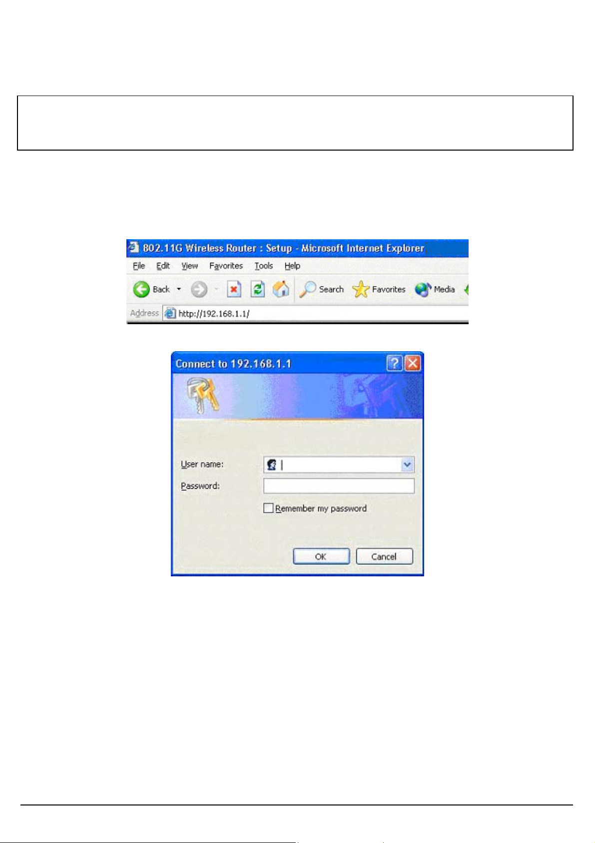
START UP & LOGIN
In order to configure the Wireless 11g AP Router, you must use your web browser and manually enter
http://192.168.1.1 into the Address box and press Enter. The Main Page will appear.
In order to configure the Wireless 11g AP Router, you must enter the password into the Password
box and leave the User Name blank. The default password is “admin”.
Once you have logged-in as administrator, it is a good idea to change the administrator password to
ensure the Wireless 11g AP Router is secure. The Security Settings section described later in this
manual describes how to change the password.
Once you have entered the correct password and logged in, the screen will change to the Setup page
screen.
Alloy Wireless 802.11g User’s Guide www.alloy.com.au
5
4.1. Setup
ENSURE YOU HAVE THE CORRECT NETWORK SETTINGS IN YOUR COMPUTER
To change the configuration, use Internet Explorer (IE) or Netscape Communicator to connect to the
WEB management 192.168.1.1.
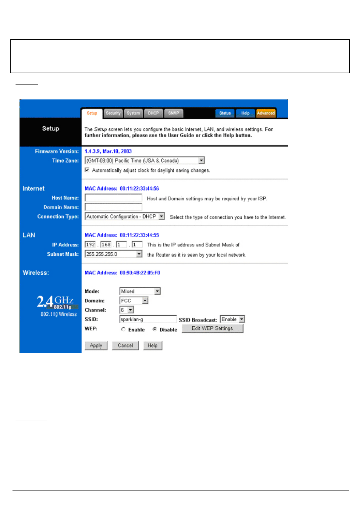
Setup
This screen contains all of the Router's basic setup functions.
.
Most users will be able to configure the AP Router and get it working properly using the settings on
this screen. Some Internet Service Providers (ISPs) will require that you enter specific information,
such as User Name, Password, IP Address, Default Gateway Address, or DNS IP Address. This
information can be obtained from your ISP, if required.
Internet:
Host Name: This entry may be necessary with some ISP’s. Please consult your ISP.
Domain Name: This entry may be necessary with some ISP’s. Please consult your ISP.
Connection Type: The Router supports four connection types:
Automatic Configuration – DHCP
Static IP
Alloy Wireless 802.11g User’s Guide www.alloy.com.au
6

PPPoE (Point-to-Point Protocol over Ethernet)
PPTP (Point-to-Point Tunneling Protocol)
These options can be selected from the drop-down menu next to Internet Connection. The information
required and available features will differ depending on what kind of connection type you select.
Descriptions of these options:
Internet IP Address and Subnet Mask (Static IP or PPTP)
This is the Router's IP Address and Subnet Mask as seen by external users on the
Internet (including your ISP). If your Internet connection requires a static IP address,
then your ISP will provide you with a Static IP Address and Subnet Mask.
• Default Gateway (Static IP or PPTP)
Your ISP will provide you with the Gateway IP Address.
• DNS (Domain Name Server or PPTP) IP Address
Your ISP will provide you with at least one DNS IP Address.
• User Name and Password (PPPoE ir PPTP)
Enter the User Name and Password you use when logging onto your ISP through a
PPPoE or PPTP connection.
• Connect on Demand
You can configure the Router to disconnect your Internet connection after a specified
period of inactivity (Max Idle Time). If your Internet connection has been terminated due
to inactivity, Connect on Demand enables the Router to automatically re-establish your
connection as soon as you attempt to access the Internet again. If you wish to activate
Connect on Demand, click the radio button.
If you want your Internet connection to remain active at all times, enter 0 in the AP
Router 802.11g AP Router max Idle Time field. Otherwise, enter the number of minutes
you want to have elapsed before your Internet connection terminates.
• Keep Alive Option
This option keeps you connected to the Internet indefinitely, even when your connection
sits idle. To use this option, click the radio button next to Keep Alive. The default Redial
Period is 30 seconds (in other words, the Router will check the Internet connection every
30 seconds).
Alloy Wireless 802.11g User’s Guide www.alloy.com.au
7
LAN IP Address and Subnet Mask: This is the Router's IP Address and Subnet Mask as seen on
the internal LAN. The default value is 192.168.1.1 for IP Address and 255.255.255.0 for Subnet Mask.
Wireless: This section provide the Wireless Network settings for your WLAN
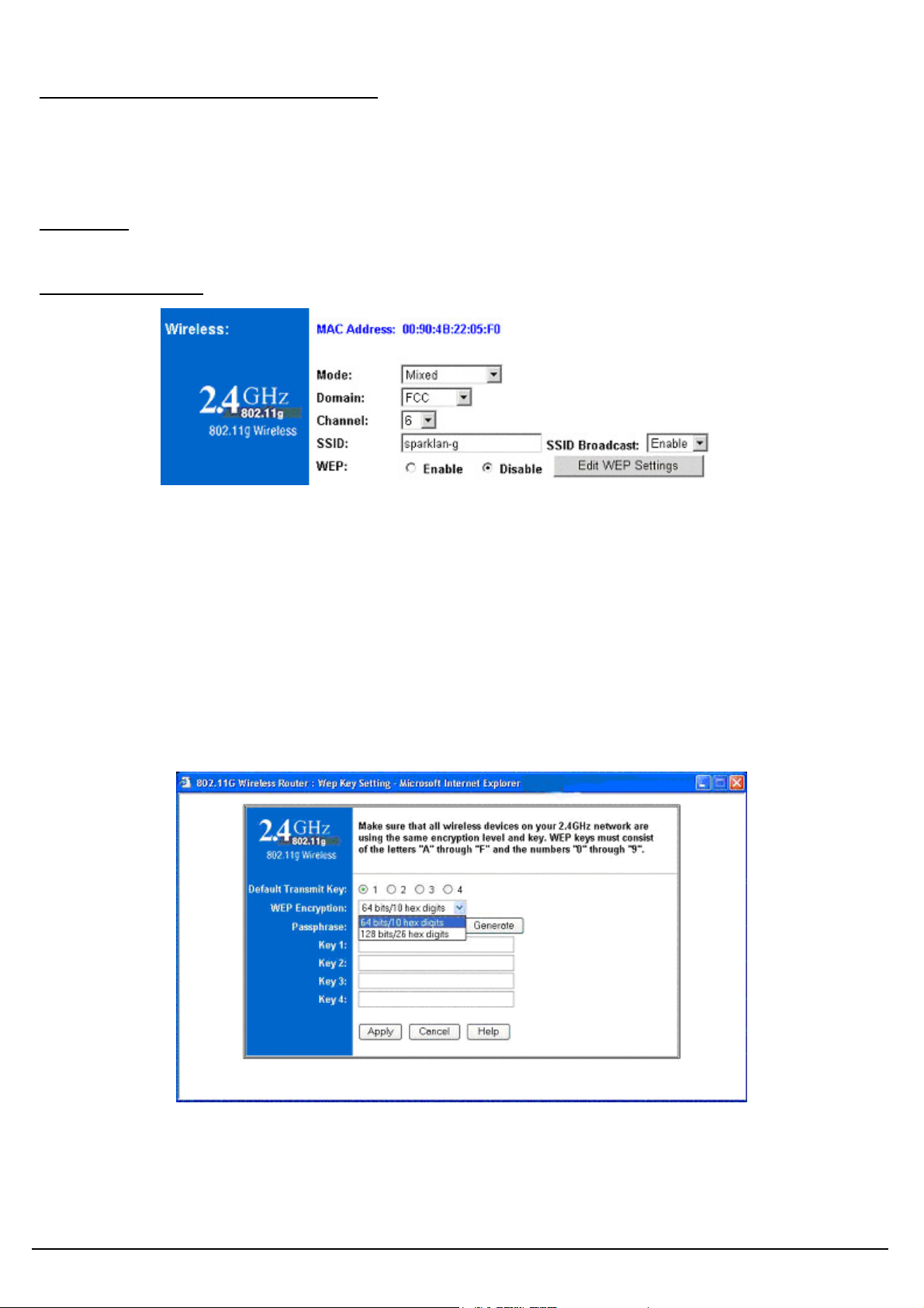
2.4GHz Settings
SSID: The service set identifier ( SSID ) or network name. It is case sensitive and must not exceed 32
characters, which may be any keyboard character. You must select the same SSID for all the APs that
will be communicating with mobile wireless stations.
Domain: Please select the correct Domain for your physical location. ETSI is recommended.
Channel: Select the appropriate channel from the list provided to correspond with your network
settings. You should assign a different channel for each AP to avoid signal interference.
WEP: Make sure that all wireless devices on your network are using the same encryption level and
key. WEP keys must consist of the letters "A" through "F" and the numbers "0" through "9."
* Click Apply to save your settings.
Alloy Wireless 802.11g User’s Guide www.alloy.com.au
8
 Loading...