

Alloy Computer Products RNS5, RNS8 User Manual
Alloy RNS5/8
Industrial 5-port/8-port Ethernet Rail Switch
User’s Manual
Rev.1.1
20-Jan-2005

Content
Introduction.........................................................1
Features................................................................... 1
Package Checklist.................................................... 2
Hardware Description.........................................3
Dimensions .............................................................. 3
Front Panel............................................................... 3
Bottom View............................................................. 5
Wiring the DC Power Inputs.....................................5
LED Indicators.......................................................... 6
Ports......................................................................... 8
Cabling..................................................................... 9
DIN-Rail Mounting.................................................. 10
Wall Mounting ........................................................ 12
Hardware Installation........................................13
Installation and Testing..........................................13

Introduction
Industrial environments are usually more demanding than office environments.
Harsh temperature conditions, vibration, dust, etc. all put higher demands on the
quality and reliability of your networking equipment. To survive harsh industrial
environments, Alloy provides you with the RNS5/8 Series Industrial 5-port/8-port
10/100Mbps Ethernet Switches. The RNS5/8 Industrial switch is a cost-effective
solution ideal for your industrial applications in harsh environments. The RNS5/8
not only gives you high speed data transmission over an Ethernet network, but
also provides redundant power inputs and reverse polarity protection. In addition,
the RNS5/8 is manufactured in an IP30 aluminum case, and has passed several
safety certifications, ensuring customers a cost-effective, safe, and reliable
industrial device.
Features
5-port /8-port 10/100T(X) industrial switch
Supports store-and-Forward switching architecture
Supports IEEE 802.3 10Base-T, 802.3u 100Base-TX standard
Supports auto MDI/MDI-X function
RNS5: 512 KB embedded memory
RNS8: 1024KB embedded memory
Supports IEEE 802.3x flow control
¾ Flow control for full-duplex mode
¾ Back pressure for half-duplex mode
Provides redundant dual power inputs
Aluminum case with IP30 protection
RNS5:1K MAC address table
RNS8:2K MAC address table
DIN-Rail and wall mountable design
1
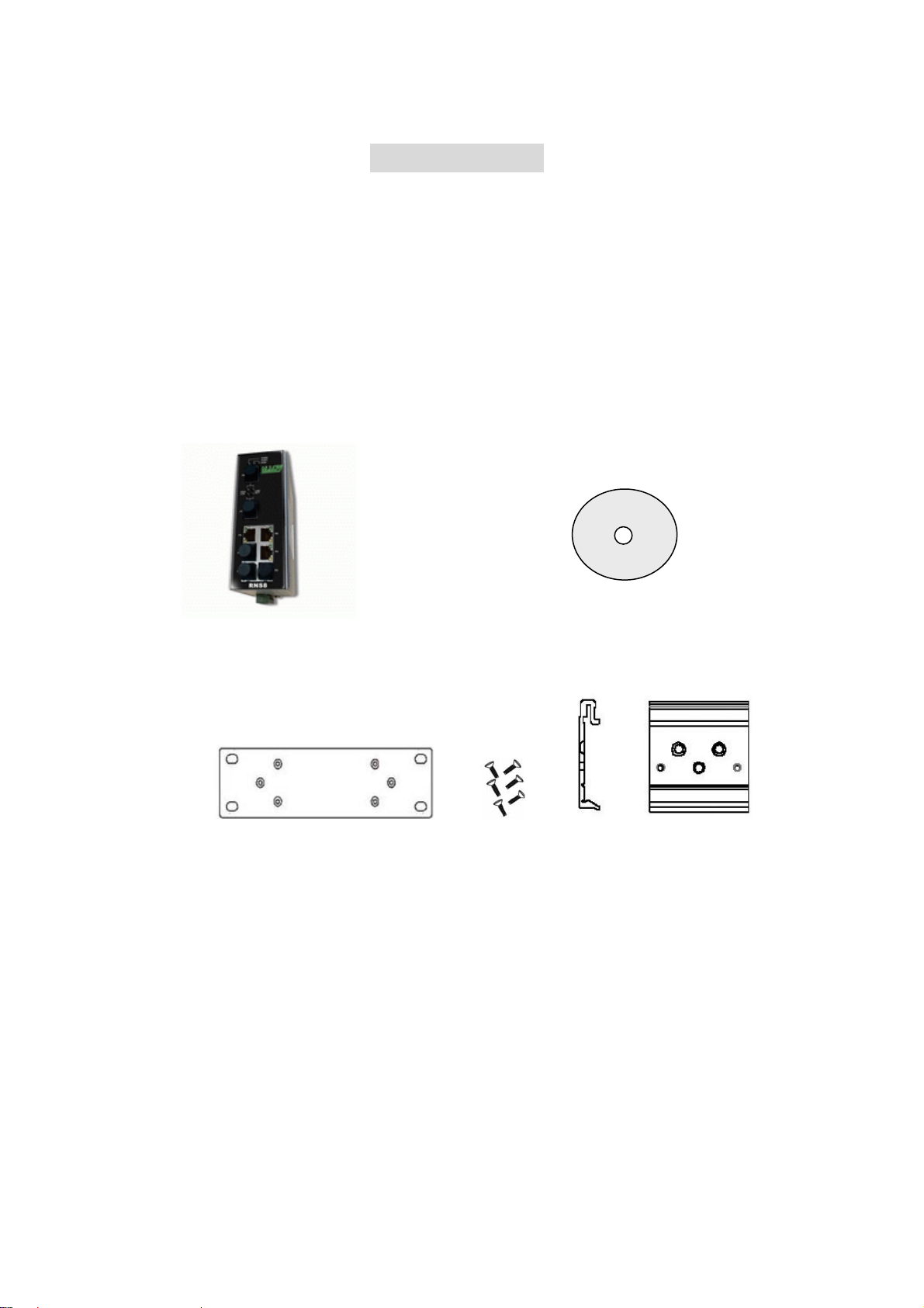
Package Checklist
Alloy RNS5/8 Industrial 5-port/8-port Ethernet Rail Switches are packaged with the
following items:
RNS5/8 Industrial 5-port/8-port Ethernet Rail Switch
One DIN-Rail clip (attached to the RNS5/8)
One wall mounting plate and six screws
User’s manual CD-ROM
RNS5/8 Switch User’s Manual CD-ROM
Wall Mounting Plate Screws DIN-Rail Clip
Contact your sales representative if any item is missing or damaged.
2

Hardware Description
Dimensions
RNS5/8 Industrial 5-port/8-port Ethernet Rail Switch dimensions (W x H x D) are
54mm x 135mm x 105mm
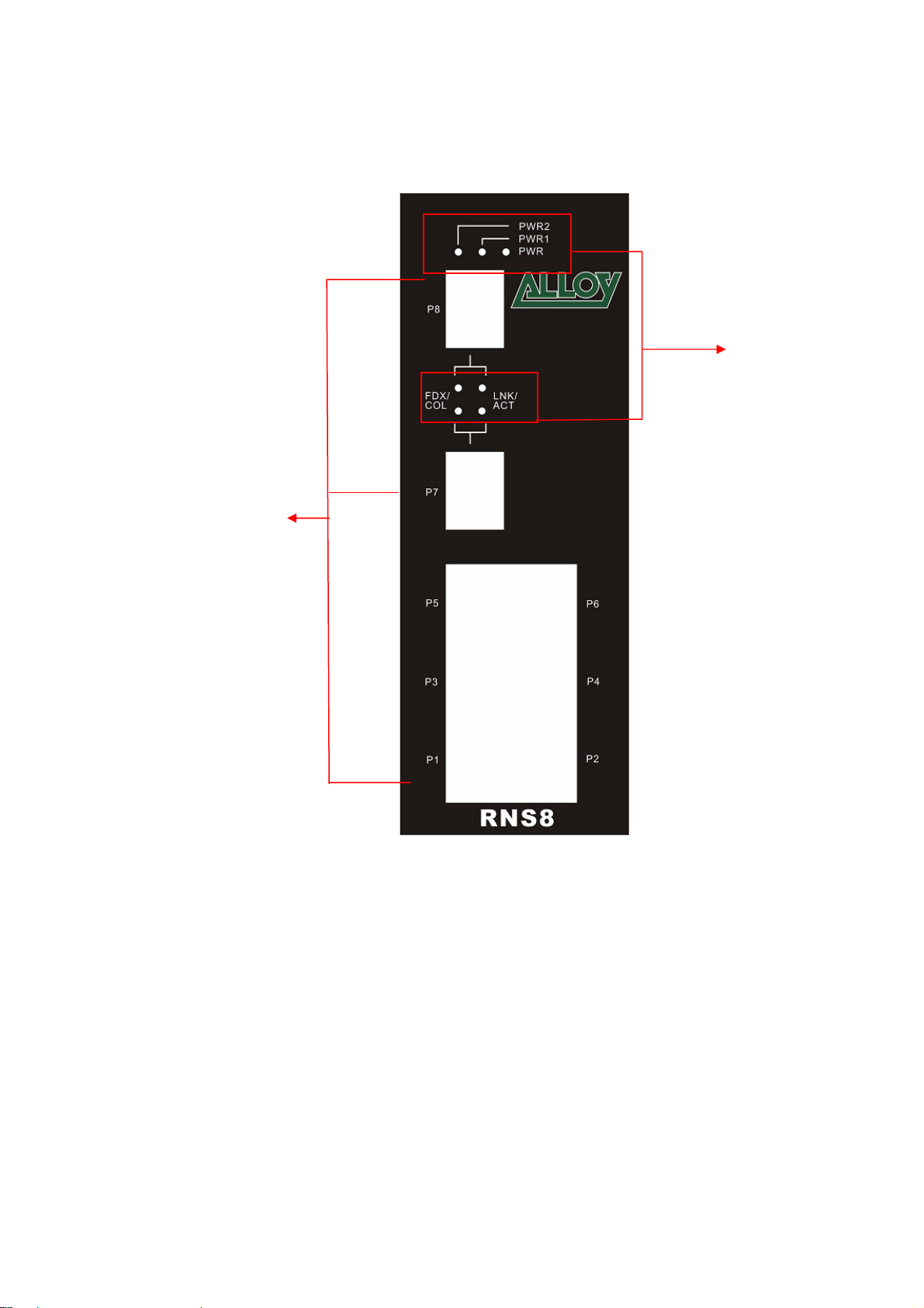
Front Panel
The Front Panel of the RNS5 Industrial 5-port Ethernet Rail Switch is shown in
Figure A.
UTP Ports
LED Indicators
Figure A. Front Panel of the RNS5 Industrial 5-port Ethernet Rail Switch
3
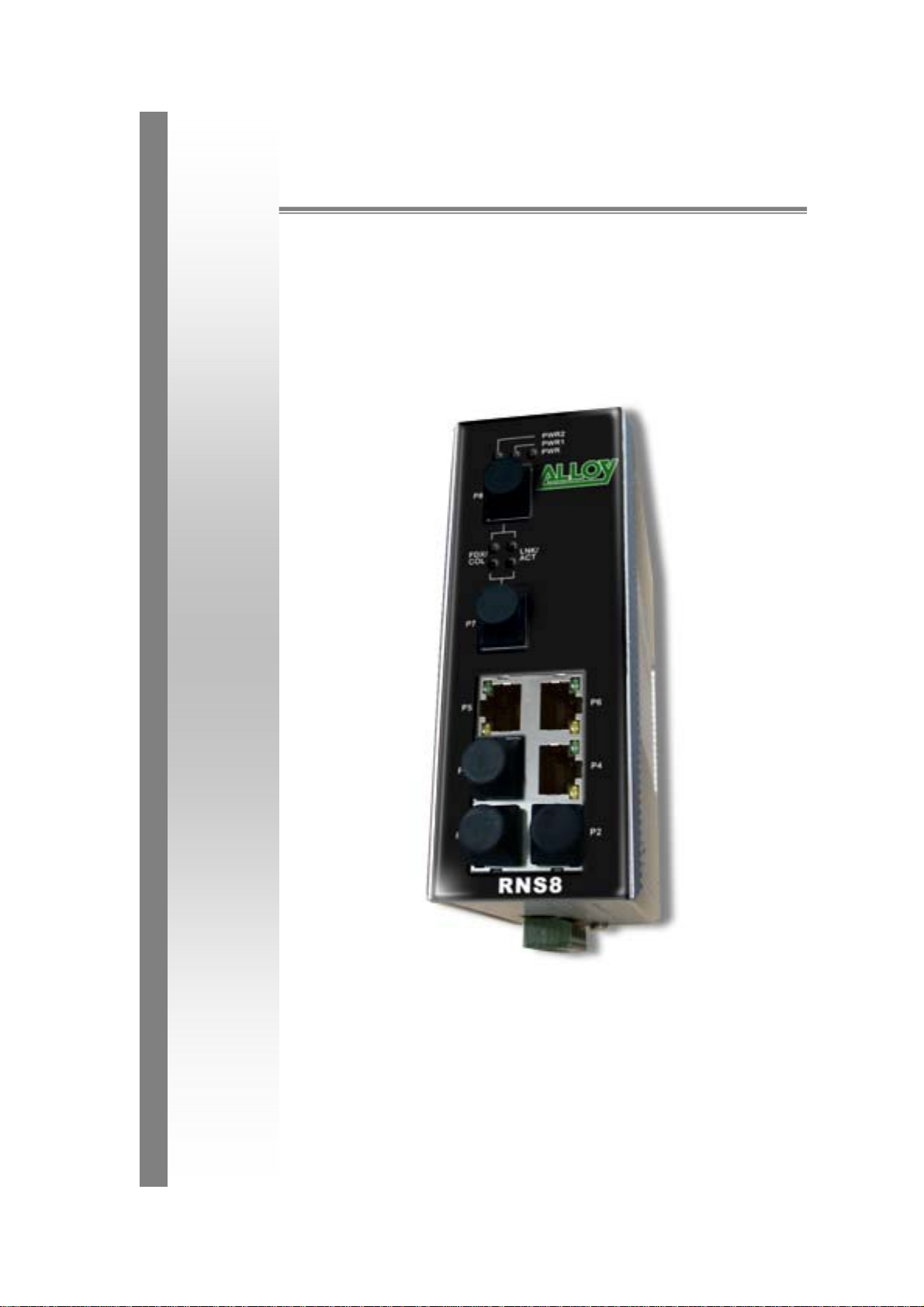
The Front Panel of the RNS8 Industrial 8-port Ethernet Rail Switch is shown in
Figure A.
LED Indicators
UTP Ports
Figure A. Front Panel of the RNS8 Industrial 8-port Ethernet Rail Switch
4
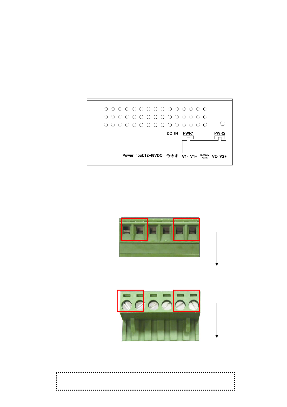
Bottom View
The bottom view of the RNS5/8 Industrial 5-port/8-port Ethernet Rail Switch
consists of one terminal block connector with two DC power inputs, Alarm output
and one DC IN power jack for an additional AC/DC power adapter.
Figure B. Bottom view of the RNS5/8 Industrial 5-port/8-port Ethernet Rail Switch
Wiring the DC Power Inputs
Follow the steps below to wire RNS5/8 dual DC power inputs.
[Note] The suitable electric wire ranges from 12 to 24 AWG.
V- V+ V- V+
1. Insert the positive and negative wires into the V+ and Vcontacts respectively of the terminal block connector
2. Tighten the wire-clamp screws to prevent the DC wires
[Note] The additional power jack is designed for office use.
from being loosened.
5
 Loading...