

Alloy Computer Products POE100 User Manual

POE100 Series
10/100 Base-TX to 100Base-FX Converter
POE Power Provider
Version 1.01
Date: 13 July 2005
1. Overview
The POE Series IEEE 802.3u compliant media converters support two types
of media 10/100 Base-TX and 100Base-FX. With LFP (Link Fault
Propagation) support it allows the administrator to easily diagnose link faults
on their network. If the Copper or Fibre link fails, the converter forces the link
status of the connecting device to also fail.
The POE100 Series of media converters are designed for applications where
the supply of power to attached Ethernet devices needs to be via the network
connection, rather than by a power cord. Typical devices that use this method
of powering are VoIP Phones, Wireless Access points and IP based Cameras.
The POE100 Series media converters are fully compliant to the IEEE 802.3af
standard. The converters include PD (Power Devices – POE120 Series, IP
Phones, Wireless Access Points etc.) signature sensing and power monitoring
features compliant with the IEEE 802.3af standard, This includes, PD
discovery, classification, current limiting and other necessary functions. It also
supports high levels of safety support with short circuit protection and powerout auto-detection to the PD.
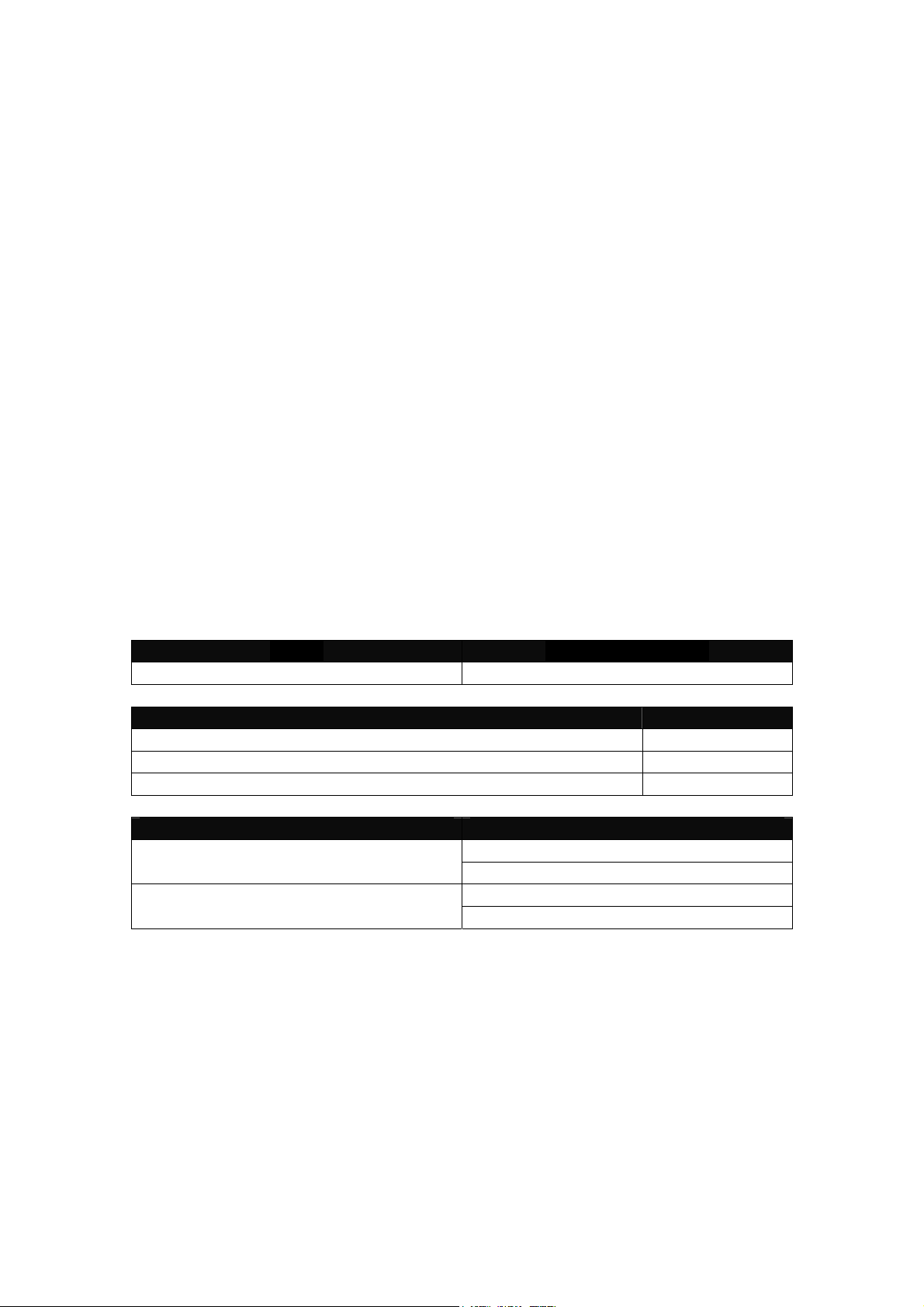
2. Model Description
Model Power Description
POE100 Series AC: 100 ~ 240V 50 ~ 60Hz
100Mbps Fibre Transceiver Wavelength
ST/SC Multimode 2Km 1310nm
SC.S05/S20/S40/S60Km Single Mode 1310nm
SC.S80/S100Km Single Mode 1550nm
Single Fibre Model TX, RX Wavelength
TX (Transmit) 1310nm 1310nm Single Mode 20Km
Note:
The 1310nm and 1550nm models must be installed in pairs,
i.e., install 1310nm model at one end and the 1550nm model at the other end.
RX (Receive) 1550nm
TX (Transmit) 1550nm 1550nm Single Mode 20Km
RX (Receive) 1310nm

3. Checklist
Before you start installing the POE converter, please verify that the package
contains the following items.
- The POE100 Series
- AC Power Cord
- CD containing this manual
Please notify your sales representative if any of the above items are missing
or damaged.
4. Installing the Converter
4.1 POE100 converter with a Powered Device (PD)
1. Connect the POE100 converter to an AC power source.
2. Connect the copper cable to your IEEE 802.3af compliant PD device.
e.g. Wireless Access Point, IP Phone, IP Camera
Note:
The POE100 can also work as a standard media converter and
connect to a non POE device.
3. Connect the fibre cable to your connecting device.
Default: Auto
Auto or Force setting, see figure 10. S1-Bit 1
TP
Port
Fibre
Port
Attach Cat. 5 cable to the copper port and ensure the cable run is not
over 100m in distance.
The Copper port supports Auto MDI-X, therefore there is no need to
use a cross-over cable when connecting to a switch.
Default: 100FDX
”100FDX”/”100HXD” setting, see figure 10. S1-Bit 5
 Loading...