

Alloy Computer Products GSS-16T4SFP, GSS-24T4SFP User Manual
GSS Series User Manual
User Manual
GSS Series
16/24 Port Gigabit Web
Managed Switch
(GSS-16T4SFP & GSS-24T4SFP)
Version 1.0
Sep. 2007
Alloy Computer Products Pty Ltd Copyright ©2007
1

GSS Series User Manual
Table of Contents
CAUTION ..............................................................................................................................................3
ELECTRONIC EMISSION NOTICES..........................................................................................................3
ABOUT THIS USER MANUAL.................................................................................................................4
OVERVIEW OF THE USER MANUAL.......................................................................................................4
1. INTRODUCTION ..............................................................................................................................5
1.1 OVERVIEW......................................................................................................................................5
1.2 KEY FEATURES...............................................................................................................................6
1.3 CHECKLIST .....................................................................................................................................6
1.4 OVERVIEW OF THE GSS RANGE OF SWITCHES.................................................................................6
1.4.1 User interfaces on the front panel..........................................................................................7
1.4.2 User interfaces on the rear panel...........................................................................................8
1.5. OVERVIEW OF THE OPTIONAL SFP MODULES ...............................................................................9
2. INSTALLATION .............................................................................................................................10
2.1. STARTING THE GSS SERIES SWITCHES ........................................................................................10
2.1.1. Hardware and Cable Installation.......................................................................................10
2.1.2. Cabling Requirements.........................................................................................................12
2.1.2.1. Cabling Requirements for UTP Ports..........................................................................................12
2.1.2.2. Cabling Requirements for 1000SX/LX/ZX SFP Modules ..........................................................12
3. OPERATION OF THE WEB BASED MANAGEMENT ............................................................14
3.1 WEB MANAGEMENT HOME OVERVIEW ........................................................................................15
3.2 CONFIGURATION...........................................................................................................................16
3.2.1 System Information..............................................................................................................16
3.2.2 Ports.....................................................................................................................................18
3.2.3 VLAN Mode..........................................................................................................................20
3.2.4 VLAN Group........................................................................................................................22
3.2.5 Aggregation..........................................................................................................................28
3.2.6 LACP....................................................................................................................................29
3.2.7 RSTP....................................................................................................................................30
3.2.8 802.1x...................................................................................................................................32
3.2.9 IGMP ...................................................................................................................................35
3.2.10 Port Mirroring...................................................................................................................36
3.2.11 Quality of Service...............................................................................................................37
3.2.12 Filter ..................................................................................................................................39
3.2.13 Rate Limit...........................................................................................................................40
3.2.14 Storm Control.....................................................................................................................41
3.2.15 SNMP.................................................................................................................................42
3.3 MONITORING ................................................................................................................................43
3.3.1 Detailed Statistics................................................................................................................43
3.3.2 LACP Status.........................................................................................................................44
3.3.3 RSTP Status..........................................................................................................................45
3.3.4 IGMP Status.........................................................................................................................46
3.3.5 Ping......................................................................................................................................47
3.4 MAINTENANCE .............................................................................................................................48
3.4.1 Warm Restart.......................................................................................................................48
3.4.2 Factory Default....................................................................................................................49
3.4.3 Software Upgrade................................................................................................................50
3.4.4 Configuration File Transfer.................................................................................................51
3.4.5 Logout..................................................................................................................................52
APPENDIX A – TECHNICAL SPECIFICATIONS.........................................................................53
Alloy Computer Products Pty Ltd Copyright ©2007
2

GSS Series User Manual
Caution
Electronic Circuit devices are sensitive to static electricity. Dry weather conditions or walking
across a carpeted floor may cause you to acquire a static electric charge.
To protect your switch, always:
• Touch the metal chassis of your computer to ground the static electrical charge before
you handle the switch.
• Pick up the switch by holding it on the left and right edges only.
Electronic Emission Notices
Federal Communications Commission (FCC) Statement
This equipment has been tested and found to comply with the limits for a Class A computing
device pursuant to Subpart J of Part 15 of FCC Rules, which are designed to provide
reasonable protection against such interference when operated in a commercial environ ment.
European Community (CE) Electromagnetic Compatibility Directive
This equipment has been tested and found to comply with the protection requirements of
European Emission Standard EN55022/EN60555-2 and the Generic European Immunity
Standard EN50082-1.
EMC:
EN55022(1988)/CISPR-22(1985) class A
EN60555-2(1995) class A
EN60555-3
IEC1000-4-2(1995) 4K V CD, 8KV, AD
IEC1000-4-3(1995) 3V/m
IEC1000-4-4(1995) 1KV – (power line), 0.5KV – (signal line)
Australian C-Tick Compliance.
This equipment is compliant with the required Australian C-Tick standards
Alloy Computer Products Pty Ltd Copyright ©2007
3

GSS Series User Manual
About this User Manual
This User Manual will guide you on procedures to install, configure and monitor Alloy 16 port
Gigabit (GSS-16T4SFP) and 24 port (GSS-24T4SFP) Gigabit web Managed Switch models
utilizing the built-in web management interface.
The two models GSS-16T4SFP and GSS-24T4SFP differ in terms of port density – the former
model offering 16x 10/100/1000Mbps Gigabit Ethernet ports, and the latter 24x ports of the
same specification. In all other respects (web management interface, for example) the two
models share identical characteristics.
Overview of the User Manual
• Chapter 1 “Introduction” describes the features of the GSS series of Gigabit Web
Managed switches
• Chapter 2 “Installation”
• Chapter 3 “Operation of the Web-based Management”
Alloy Computer Products Pty Ltd Copyright ©2007
4

GSS Series User Manual
1. Introduction
1.1 Overview
Alloy 16/24 Port Gigabit Switches meet all IEEE 802.3/u/x/z standards Gigabit and Fast
Ethernet specifications. The 16 Port Gigabit Switch model features 16x 10/100/1000Mbps
copper RJ-45 ports and 4x Gigabit Ethernet SFP Ports. The SFP ports can be used to install
a range of optional mini-GBIC Gigabit Ethernet Port Modules (which provide the ability to
connect multimode and/or single mode fibre optic cable links – see belo w); the SFP ports a re
each paired with one of the 10/100/1000Mbps copper RJ-45 ports. The 24 Port Gigabit Switch
is identical other than featuring 24x 10/100/1000Mbps copper RJ-45 ports. Both switches are
managed through any of their Ethernet RJ-45 ports, using a web-based browser such as
Internet Explorer.
The SFP ports can support the following optional mini-GBIC modules for fibre optic cable
connections (either single mode or multimode terminated in LC type connectors):
• 1000Mbps multimode 1000Base-SX, 850nm, max. range 500m
• 1000Mbps single mode 1000Base-LX, 1310nm, max. range 10Km
• 1000Mbps single mode 1000Base-LHX, 1310nm, max. range 40Km
• 1000Mbps single mode 1000Base-LHX, 1550nm, max. range 40Km
• 1000Mbps single mode 1000Base-ZX, 1550nm, max. range 70Km
• 1000Mbps single mode 1000Base-EZX, 1550nm, max. range 120Km
• 1000Mbps WDM single mode/single core 1310nm, max. range 20Km
• 1000Mbps WDM single mode/single core 1550nm, max. range 20Km
• 1000Mbps WDM single mode/single core 1310nm, max. range 40Km
• 1000Mbps WDM single mode/single core 1550nm, max. range 40Km
• 1000Mbps CWDM single mode/single core 1470 - 1610nm, max. range 70Km
Notes: * The two WDM (Wave Division Multiplexer) mini-GBIC modules are
designed to facilitate a link over a single core of single mode fibre cable.
The two units must be used in a paired manner, one at either end of the link.
* Mini-GBIC modules that are designed to the relevant standards should be
compatible with any make of switch with SFP ports. If you have concerns
regarding compatibility, please contact the supplier of your mini-GBIC
product.
The 10/100/1000Mbps copper ports meet all IEEE 802.3/u/x/z Gigabit and Fast Ethernet
specifications.
The 1000Mbps SFP Fibre ports via optional mini-GBIC modules are compliant with all IEEE
802.3z and 1000Base-SX/LX/LHX/ZX/EZX standards.
1000Mbps single fibre WDM transceivers are designed with an optic Wavelength Division
Multiplexing (WDM) technology that transports bi-directional full duplex signals over a single
fibre core.
Alloy Computer Products Pty Ltd Copyright ©2007
5
GSS Series User Manual
1.2 Key Features
• 16 or 24 10/100/1000Mbps Gigabit Ethernet Ports all compliant with IEEE802.3,
802.3u, 802.3z and 802.3ab
• 4 Paired TP/SFP fibre ports
• Web Based Management
• Port Based VLAN and Tag-based (IEEE802.1q) VLAN
• 802.1p Class of Service with 2 level priority queuing
• Port Trunking with flexible load distribution and failover function
• Port mirroring function
1.3 Checklist
Before you start installing your switch, verify that the package contains the following:
• A GSS-16T4SFP or GSS-24T4SFP Gigabit Web Managed Switch
• Mounting Accessories (for 19” Rack Shelf mounting)
• CD-ROM
• AC Power Cord
Please notify your supplier immediately if any of the aforementioned items are missing or
damaged.
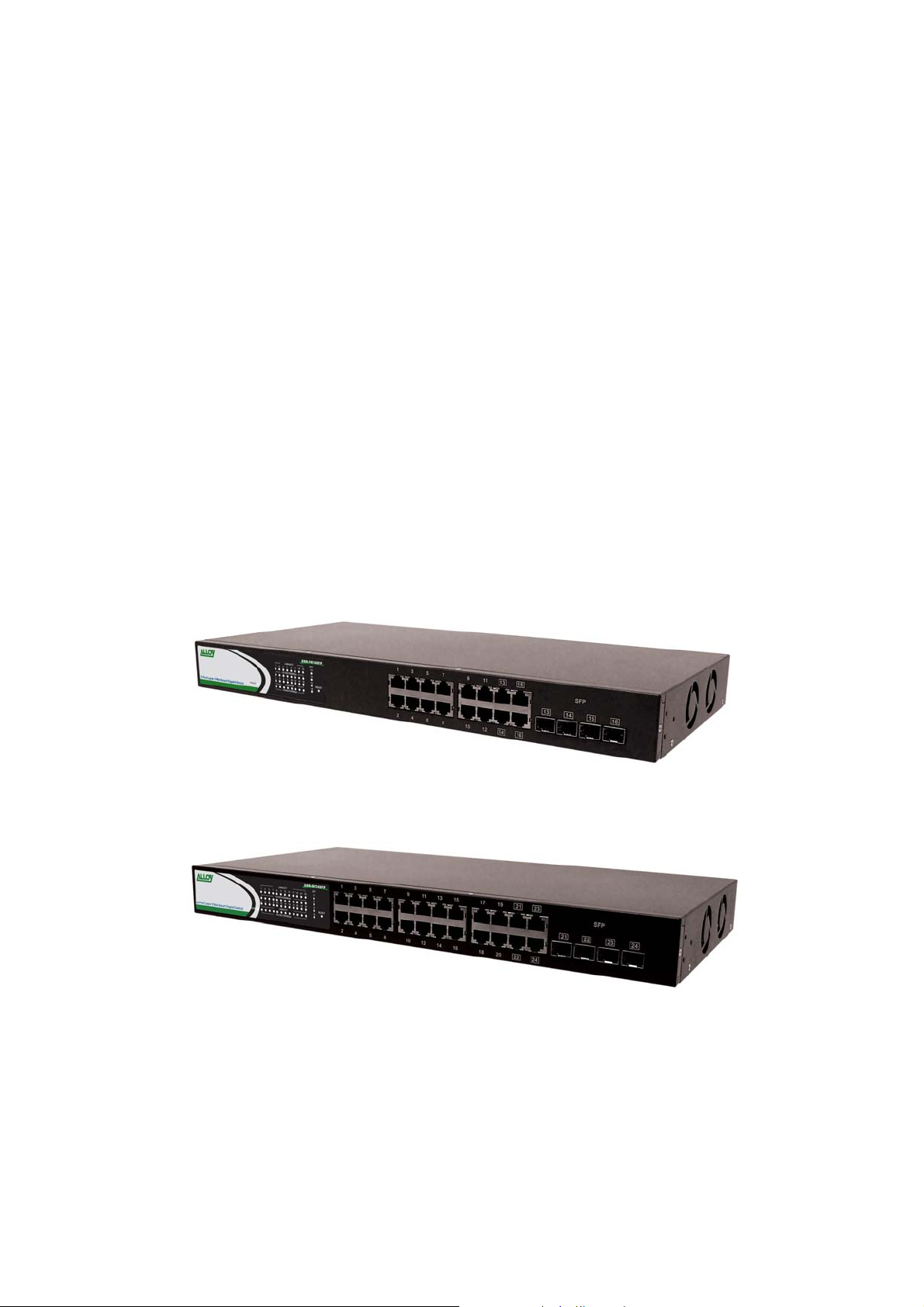
1.4 Overview of the GSS range of switches
Fig. 1.1 Front view of the GSS-16T4SFP switch
Fig. 1.2 Front view of the GSS-24T4SFP switch
Alloy Computer Products Pty Ltd Copyright ©2007
6
GSS Series User Manual
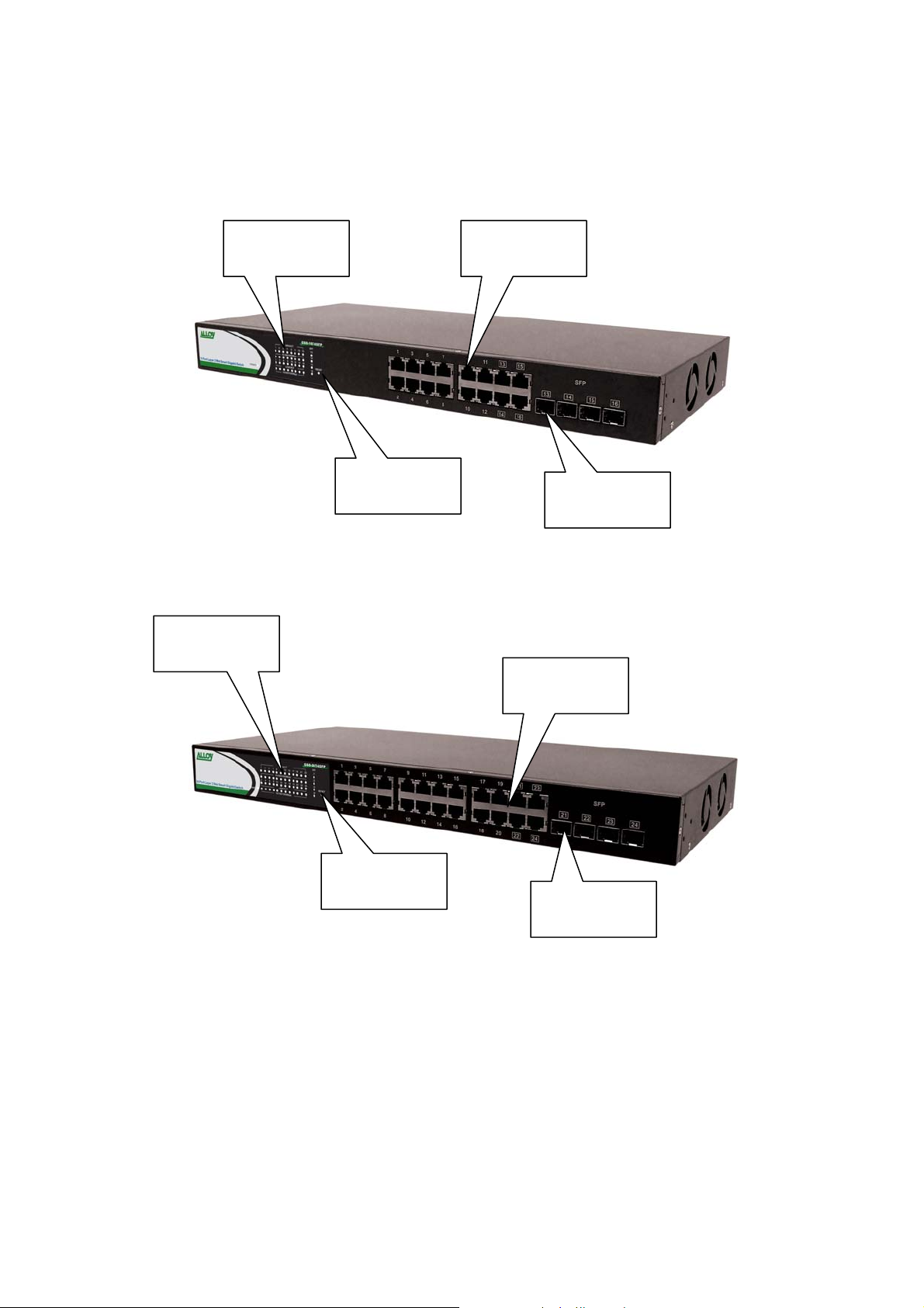
1.4.1 User interfaces on the front panel
The front panel of the GSS-16T4SFP and GSS-24T4SFP consists of 16x or 24x
10/100/1000Mbps Copper Gigabit Ethernet ports, 4x SFP fibre ports and 1x reset button to
restore factory configuration.
LED Display
Panel
Gigabit
Ethernet Ports
LED Display
Panel
Factory
Default Button
Fig. 1.3 Front Panel of the GSS-16T4SFP
Factory
Default Button
Fig. 1.4 Front Panel of the GSS-24T4SFP
Ethernet Ports
SFP Fibre
Ports
Gigabit
SFP Fibre
Ports
Alloy Computer Products Pty Ltd Copyright ©2007
7
GSS Series User Manual
LED Indicators
LED COLOUR FUNCTION
System LED’s
Power Green Lit when Power is active
Gigabit Copper Ports
Link/Act Green Lit when link is active, flashes when traffic is present
10/100/1000Mbps Green/Amber Lit green when 1000Mb link
Lit amber when 100Mb link
Off when 10Mb link or no link present
Gigabit Fibre Ports
SFP(LINK/ACT) Green Lit when link is active, flashes when traffic present
Note: All SFP ports are paired with one of the 10/100/1000Mbps cop per RJ-45 ports. Only
one of the paired ports can be used.
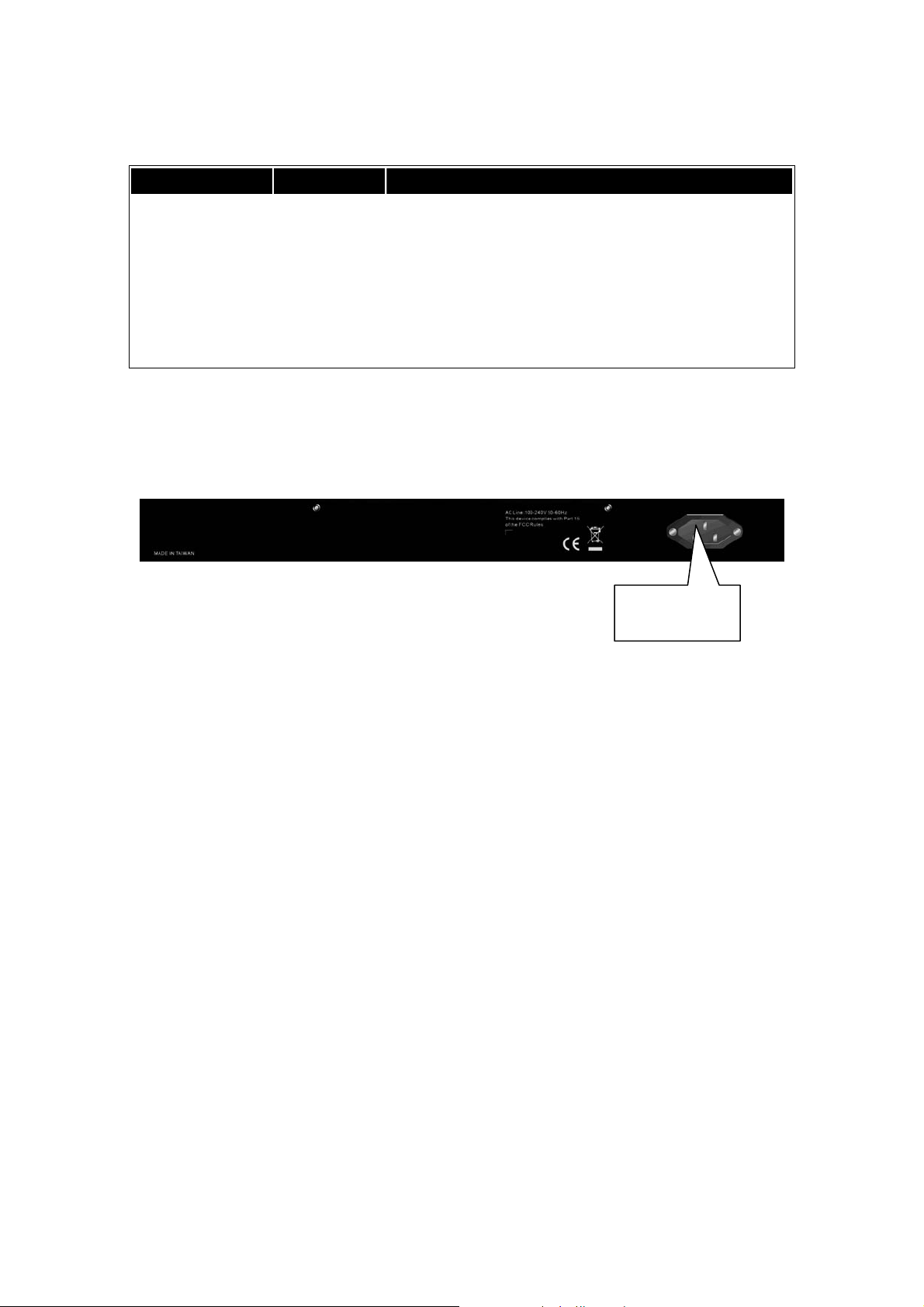
1.4.2 User interfaces on the rear panel
Fig. 1.5 Rear Panel of the GSS-16T4SFP & GSS-24T4SFP
Mains Power
Plug
Alloy Computer Products Pty Ltd Copyright ©2007
8

GSS Series User Manual
1.5. Overview of the Optional SFP Modules
With the GSS-16T4SFP switch, the SFP ports are paired with RJ-45 copper ports 13, 14, 15
and 16. In the case of the GSS-24T4SFP, the SFP ports are paired with RJ-45 copper ports
21, 22, 23 and 24. Only one of any given paired port can be used. In this manner, these
paired ports can be seen as ‘Dual Media’ ports that support 10/100/1000Mbps or 1000Mbps
fibre via the SFP interfaces.
Optional 1000Mbps mini-GBIC fibre transceiver modules can be used for high-speed uplink
connections to fibre backbones or servers, when installed in the SFP ports. A range of
optional Alloy mini-GBIC modules are available:
Alloy Part No. Description
MGBIC-MLC
MGBIC-SLC10
MGBIC-SLC4013
MGBIC-SLC4015
MGBIC-SLC70
MGBIC-SLC120
MGBIC-WDMS3.20
MGBIC-WDMS5.20
MGBIC-WDMS3.40
MGBIC-WDMS5.40
MGBIC-CWDM-70
1000Mbps multimode 1000Base-SX, 850nm, max. range 500m
1000Mbps single mode 1000Base-LX, 1310nm, max. range 10Km
1000Mbps single mode 1000Base-LHX, 1310nm, max. range 40Km
1000Mbps single mode 1000Base-LHX, 1550nm, max. range 40Km
1000Mbps single mode 1000Base-ZX, 1550nm, max. range 70Km
1000Mbps single mode 1000Base-EZX, 1550nm, max. range
120Km
1000Mbps WDM single mode/single fibre 1310nm, max. range
20Km
1000Mbps WDM single mode/single fibre 1550nm, max. range
20Km
1000Mbps WDM single mode/single fibre 1310nm, max. range
40Km
1000Mbps WDM single mode/single fibre 1550nm, max. range
40Km
1000Mbps CWDM single mode/single fibre 1470 -1610nm, max.
range 70Km
Notes: * The WDM (Wave Division Multiplexer) mini-GBIC modules are
designed to facilitate a link over a single core of single mode fibre cable.
The two units must be used in a paired manner, one at either end of the link.
* Mini-GBIC modules that are designed to the relevant standards should be
compatible with any make of switch with SFP ports. If you have concerns
regarding compatibility, please contact the supplier of your mini-GBIC
product.
* The information given in the table above is current at time of publication;
availability of individual Alloy mini-GBIC modules may vary over time.
Fig. 1.4: Front View of
1000Base-SX/LX LC,
SFP Fibre Transceiver
Fig. 1.5: Front View of
1000Base-LX WDM LC
SFP Fibre Transceiver
Alloy Computer Products Pty Ltd Copyright ©2007
9
GSS Series User Manual
2. Installation
2.1. Starting the GSS Series Switches
This section provides a quick start guide for:
• Hardware and Cable Installation
• Management Station Installation
• Software booting and configuration
2.1.1. Hardware and Cable Installation
Please Note:
⇒ Wear a grounding strap to avoid damaging the switch with electrostatic discharge
⇒ Be sure that the power switch is in the ‘OFF’ position before you insert the power cord
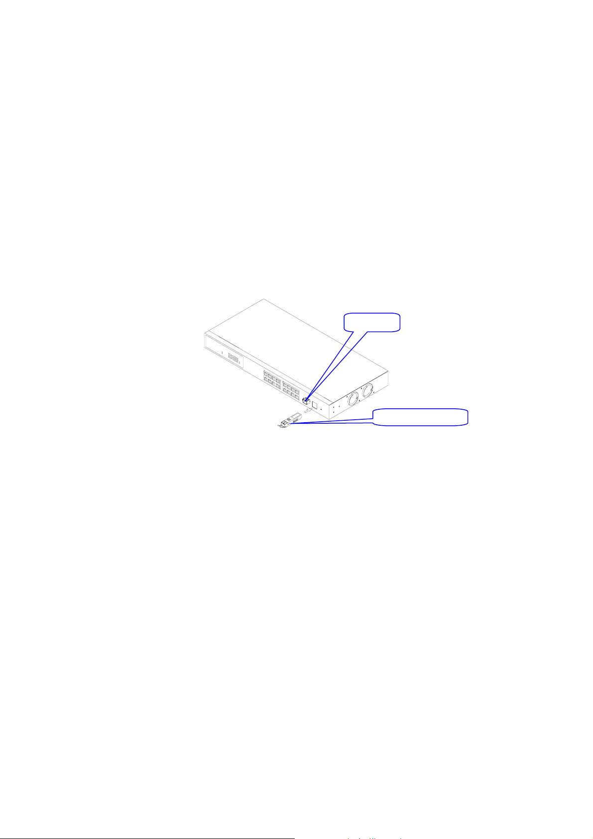
Installing Optional SFP Mini-GBIC Modules
•
SFP port
Fig. 2.1: Installation of optional
SFP mini-GBIC
Mini-GBIC module
• Connecting the SFP Mini-GBIC Module to the Chassis:
The optional SFP Mini-GBIC modules are hot-swapp able, so you can plug or unplug them
while the power is applied to the switch.
1. Verify that the mini-GBIC module is compatible with the SFP port on the switch (for
example, some switch manufacturers design their mini-GBIC modules to be operable only
in their branded devices).
2. Verify that the type of mini-GBIC you have selected for use will be compatible with the type
of fibre optic cable that is to be used.
3. Verify that the type of mini-GBIC you have selected for use will be compatible with the
fibre optic transceiver at the other end of the link (e.g. – compatible wavelength and
standard)
4. Slide the module along the slot and ensure that the module is properly seated against the
SFP slot socket/connector.
5. Install the media cable for network connection
6. Repeat the above steps, as needed, for each module to be installed into the switch
Alloy Computer Products Pty Ltd Copyright ©2007
10

GSS Series User Manual
• Copper Ports - Cable Installation
Please Note:
⇒ The RJ-45 ports on the GSS Series Gigabit Switches support MDI/MDI-X auto-
crossover functionality. This enables use of either straight-through or crossover
UTP cable types; the RJ-45 ports will automatically be configured to suit the
characteristics of the device at the remote end of the link.
⇒ The RJ-45 ports on Alloy 16/24 Port Gigabit Switches supp ort Nway auto-negotiation; the
ports will automatically be configured to be compatible with the speed and duplex settings
of the device at the remote end of the link.
⇒ The minimum grade of cable for use with the switch is Cat.5e grade UTP or STP.
Higher grades of UTP/STP cable may also be used to connect to the copper RJ-45 ports.
1. Depress the clip on the RJ-45 connector and push into the RJ-45 port. Release
connector and ensure that the cable connector is securely locked into the RJ-45 port.
2. Repeat the above steps, as needed, for each RJ-45 port to be connected.
• Power On
Please Note:
⇒ Alloy GSS series switches use a 100-240 VAC, 50-60 Hz power supply. The power supply
will automatically convert your local AC power source to DC power for use by the switch.
1. Ensure that the power switch is turned off before connecting mains power
2. Connect the power cord supplied with the switch to your nearest mains outlet
3. Connect the other end of the power cord into the IEC power port on the switch
4. Lock the power cable into place using the power cable clamp mounted on the IEC power
port
5. Turn the switch on
6. When initial power is applied, all the LED indicators will light up for a brief period while the
system performs its startup tests. Once the initial tests have completed all except the
power LED should return to an off state.
• Firmware Loading
After power on, the boot-loader will load the switch firmware into the main operational
memory. This process will take about 30 seconds. Once completed, the switch will flash all
the LED’s once and then switch to a ready state.
Alloy Computer Products Pty Ltd Copyright ©2007
11

GSS Series User Manual
2.1.2. Cabling Requirements
To help ensure a successful installation and keep network performance at optimum levels,
take care to use Cat.5E grade or higher cabling. Ensure that stranded core UTP cable, if
used, runs for no more than 10 metres, and that solid core runs for a maximum of 100metres.
Poor cabling is the most common cause for network dropouts or poor performance.
2.1.2.1. Cabling Requirements for UTP Ports
• For Ethernet copper network connections, the UTP cable used must be Cat.3 grade as a
minimum, with a maximum length of 100 metres
• For Fast Ethernet copper network connections, the UTP cable used must be Cat.5 grade
as a minimum, with a maximum length of 100 metres
• For Gigabit Ethernet copper network connection, UTP cable used must be Cat.5 grade or
higher, with a maximum length of 100 metres. Cat.5e grade UTP cable is recommended.
2.1.2.2. Cabling Requirements for 1000SX/LX/ZX SFP Modules
There are two categories of fibre optic cable - multimode (MM) and single mode (SM). The
later is categorised into several classes by the distance it supports. These are SX, LX, LHX,
ZX and EZX. The majority of mini-GBIC modules available use a LC type connector. The
connector types used currently on Alloy mini-GBIC modules are LC and WDM SC, for the
following module types:
• Gigabit Fibre with multimode LC mini-GBIC modules
• Gigabit Fibre with single mode LC mini-GBIC modul es
• Gigabit Fibre with single mode/si ngle core WDM SC 1310nm mini-GBIC modules
• Gigabit Fibre with single mode/si ngle core WDM SC 1550nm mini-GBIC modules
The following table; lists the types of fibre optic cable that are supported by SFP mini-GBIC
modules installed in the GSS series switches. Other cable types not listed here may be
supported; please contact the supplier of your switch for details.
Multimode Fibre Cable and Modal Bandwidth
IEEE 802.3z
Gigabit Ethernet
1000SX 850nm
1000BaseLX/LHX/XD/ZX
1000Base-LX
Single Fibre
(WDM SC)
Multimode 62.5/125μm Multimode 50/125μm
Modal
Bandwidth
160MHz-Km 220m 400MHz-Km 500m
200MHz-Km 275m 500MHz-Km 550m
Single mode transceiver 1310nm 10Km, 40Km
Single mode transceiver 1550nm 40Km, 70Km, 120Km
Single mode
*20Km, 40Km
Single mode
*20Km, 40Km
Range
Single mode Fibre 9/125μm
Modal
Bandwidth
TX(Transmit) 1310nm
RX(Receive) 1550nm
TX(Transmit) 1550nm
RX(Receive) 1310nm
Range
Alloy Computer Products Pty Ltd Copyright ©2007
12

GSS Series User Manual
Cont.
Please Note:
⇒ Further information can be found in section 1.5 on page 7
⇒ All figures denoting the range a given cable type can achieve must be treated as
maximum values. A number of variables can limit the actual range that can be achieved
– grade of cable used, quality of cable, and presence of joins in cable runs, for example
Alloy Computer Products Pty Ltd Copyright ©2007
13
GSS Series User Manual
3. Operation of the Web Based Management
The following chapter allows the administrator to monitor and manage the GSS seri es through
the web management interface. Management functionality such as Port Based and 802.1q
VLAN, Port Aggregation (Trunking), QoS, Port configuration and much more can all be
configured quickly and easily via any port of the GSS series switches.
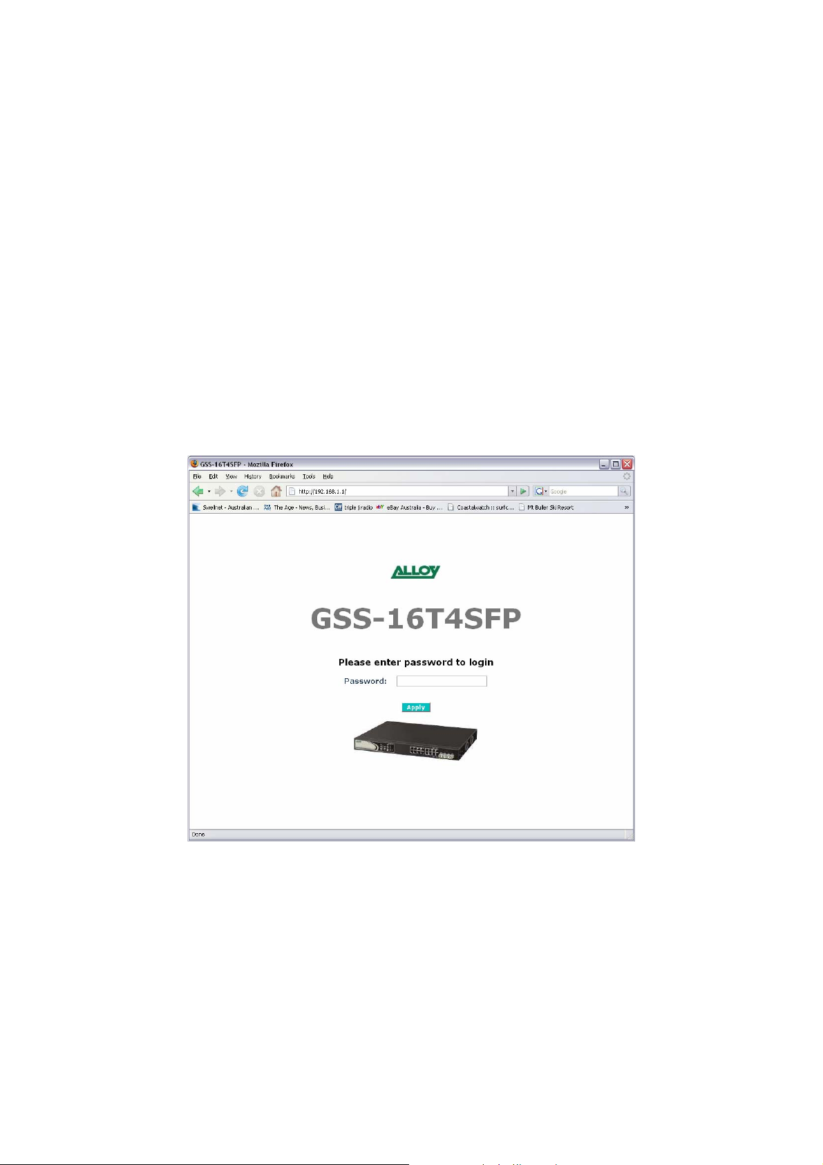
To access the web management open a web browser such as Internet Explorer or Mozilla
Firefox and enter the default IP address into the address bar.
The default network settings for the GSS Series are shown below:
IP Address: 192.168.1.1
Subnet Mask: 255.255.255.0
Gateway: 192.168.1.254
Password: admin
Once you have entered the IP address of the GSS Series switch into a web browser you will
be prompted with a login screen where you will need to enter a valid password to gain access
to the switch. The default password is shown above.
Fig. 3.1
Alloy Computer Products Pty Ltd Copyright ©2007
14

GSS Series User Manual
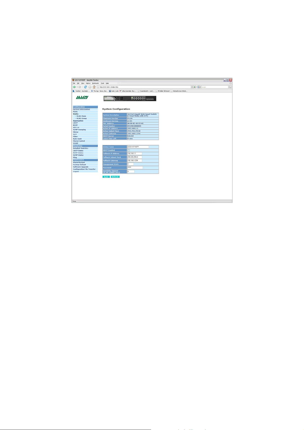
3.1 Web Management Home Overview
Once you have entered a valid password and logged into the switch the System Configuration
page will be displayed, this is the default page, it will be displayed every time that you log into
the switch.
On the left hand side of the screen you will see a menu structure used to Configure, Monitor
and manage your switch. There are three main menu categories Configuration, Monitoring
and Maintenance.
Configuration
• System – Displays system information including Model Name, Firmware Version,
Hardware Version, MAC Address etc. Also used to configure IP and SNMP settings.
• Ports – Displays link status of each port and also used to configure port speed, flow
control and jumbo frame settings.
• VLAN Mode – Used to select the VLAN mode. Modes available are Tag-Based, Port
Based and Metro Mode.
• VLAN Group - Used to configure VLAN settings.
• Aggregation – Used to configure port trunk groups.
• LACP – Used to configure LACP (Link Aggregation Control Protocol) settings.
• 802.1x – Used to configure 802.1x authentication settings.
• IGMP Snooping – Used to configure IGMP settings.
• Mirror – Used to configure Port Mirroring features.
• QoS – Used to configure QoS settings.
• Filter – Used to configure filtering features.
• Rate Limit – Used to configure Rate Limiting settings.
• Storm Control – Used to configure Storm Control settings.
• SNMP – Used to configure SNMP settings.
Monitoring
• Detailed Port Statistics – Used to view detailed traffic statistics on each port.
• LACP Status – Displays LACP status.
• RSTP Status – Displays RSTP status.
• IGMP Status – Displays IGMP status.
• Ping – Used to test connectivity between other network devices.
Maintenance
• Warm Restart – Used to restart the switch.
• Factory Default – Used to reset the switch to factory default settings.
• Software Upgrade – Used to upgrade the firmware in the switch.
• Configuration File Transfer– Used to b ackup and restore the configuration of the
switch.
• Logout – Used to Logout of the web management.
Alloy Computer Products Pty Ltd Copyright ©2007
15
GSS Series User Manual
3.2 Configuration
3.2.1 System Information
The System Information configuration page is used to display basic switch information
including the Model Name, MAC Address, Firmware Version, Hardware V ersion, IP and
SNMP information.
Fig. 3.2
System Desc: Displays a brief description of the switch. (Read Only)
F/W Version: Displays the current firmware loaded into the switch. (Read Only)
H/W Version: Displays the current hardware version. (Read Only)
MAC Address: Displays the MAC Address of the switch. (Read Only)
Serial Number: Displays the serial number of the switch. (Read Only)
Active IP Add: Displays the current IP address of the switch. (Read Only)
Active Sub Mask: Displays the current subnet mask of the switch. (Read Only)
Active Gateway: Displays the current Default Gateway. (Read Only)
DHCP Server: Displays the IP address of the DHCP Server. (Read Only)
Lease Time: Displays the amount of time left in the DHCP lease period. (Read Only)
Device Name: Enter the device name in the space provided.
DHCP Enabled: Used to enable the DHCP client on the switch. If you have a DHCP
Server running on your network and you want the switch to have a
dynamic IP Address, enable this feature.
IP Address: If you are not using the DHCP client and want to configure a static IP
Address into the switch, enter it here.
Subnet Mask: Enter a valid subnet mask into the space provided.
Gateway: Enter a valid gateway address into the space provided.
Alloy Computer Products Pty Ltd Copyright ©2007
16

GSS Series User Manual
Management
VLAN: Enter the VLAN group used to gain access to the web management.
Default value is 1. If you change this value only ports belonging to the
VLAN group chosen can manage the switch.
Password: If you want to change the default password of the switch please enter it
here. Default password is admin.
Inactivity Timeout: Used to automatically log you out of the management interface after a
specified inactivity time. Time is measured in Seconds, Default value is 0.
Apply Button: The Apply button must be pressed after making any changes to any of
the values on this screen.
Refresh Button: Used to refresh the current settings displayed on the screen.
Alloy Computer Products Pty Ltd Copyright ©2007
17
 Loading...