

Alloy Computer Products GSM-8T16SFP, GSM-16T2SFP, GSM-24T2SFP User Manual

User Manual
GSM-16T2SFP
16 Port Gigabit SNMP Managed Switch
16x 10/100/1000Mbps ports + 2 paired SFP Ports
GSM-24T2SFP
24 Port Gigabit SNMP Managed Switch
24x 10/100/1000Mbps ports + 2 paired SFP Ports
GSM-8T16SFP
24 Port Gigabit SNMP Managed Switch
8x 10/100/1000Mbps ports + 16 SFP Ports
Version: 1.01
March 1, 2006

GSM Series User Manual
TABLE OF CONTENTS
CAUTION................................................................................................................................IV
ELECTRONIC EMISSION NOTICES.............................................................................................IV
ABOUT THIS USER MANUAL......................................................................................................1
OVERVIEW OF THE USER MANUAL ............................................................................................1
1.1. OVERVIEW OF GSM SERIES SNMP MANAGED SWITCHES..................................................2
1.2. CHECKLIST.......................................................................................................................3
1.3. FEATURES........................................................................................................................4
1.4. OVERVIEW OF GSM SERIES SWITCHES .............................................................................5
1.4.1. User Interfaces on the Front Panel (Button, LED's and Plugs)..............................6
1.4.2. User Interfaces on the Rear Panel .........................................................................7
1.5. OVERVIEW OF THE OPTIONAL SFP MODULES.....................................................................7
2.1. STARTING THE GSM SERIES SNMP MANAGED SWITCHES..................................................9
2.1.1. Hardware and Cable Installation.............................................................................9
2.1.2. Cabling Requirements ..........................................................................................11
2.1.2.1. Cabling Requirements for UTP Ports.......................................................................... 11
2.1.2.2. Cabling Requirements for 1000SX/LX/ZX SFP Modules.............................................11
2.1.3. Management options available with the GSM Series Switches............................12
2.1.3.1. Configuring the GSM Series switches through the RS-232 serial port........................12
2.1.3.2. Configuring the GSM Series switches through the Ethernet Port................................14
3-1. WEB MANAGEMENT HOME OVERVIEW.............................................................................17
3-1-1. System Information...............................................................................................19
3-1-2. IP Configuration....................................................................................................21
3-1-3. Time Configuration ...............................................................................................23
3-1-4. Account Configuration ..........................................................................................25
3-1-5. Management Security Configuration....................................................................27
3-1-6. Virtual Stack Configuration...................................................................................29
3-2. PORT CONFIGURATION....................................................................................................30
3-2-1. Port Status............................................................................................................30
3-2-2. Port Configuration.................................................................................................34
3-2-3. Simple Counter.....................................................................................................36
3-2-3. Detail Counter.......................................................................................................38
3-3. MIRROR .........................................................................................................................41
3-4. BANDWIDTH....................................................................................................................42
3-5. QOS (QUALITY OF SERVICE)...........................................................................................44
3-6. SNMP CONFIGURATION..................................................................................................51
3-7. IGMP SNOOPING............................................................................................................53
3-7-1. Status....................................................................................................................53
3-7-2. Allowed Group......................................................................................................55
3-8. MAX. PACKET LENGTH....................................................................................................56
3-9. DHCP BOOT..................................................................................................................57
3-10. VLAN (VIRTUAL LOCAL AREA NETWORK).......................................................................58
3-10-1. VLAN Mode ........................................................................................................58
3-10-2. Tag-based Group................................................................................................61
3-10-3. Port-based Group...............................................................................................63
3-10-4. Tag Rule..............................................................................................................66
3-11. MAC TABLE..................................................................................................................68
3-11-1. MAC Table Information.......................................................................................68
3-11-2. MAC Table Maintenance.....................................................................................70
3-11-3. Static Forward.....................................................................................................71
3-11-4. Stat ic Filter..........................................................................................................72
3-11-5. MAC Alias...........................................................................................................73
3-12. GVRP.........................................................................................................................74
3-12-1. GVRP Configuration...........................................................................................74
3-12-2. GVRP Counter....................................................................................................76
Alloy Computer Products Pty Ltd Copyright ©2006

GSM Series User Manual
3-12-3. GVRP Group Information ...................................................................................78
3-13. STP.............................................................................................................................79
3-13-1. STP Status..........................................................................................................79
3-13-2. STP Configuration..............................................................................................81
3-13-3. STP Port Configuration.......................................................................................83
3-14. TRUNKING CONFIGURATION...........................................................................................85
3-14-1. Trunk Port Settings/Status..................................................................................86
3-14-2. Aggregator View.................................................................................................88
3-14-2-1. LACP Detail..............................................................................................................89
3-14-3. LACP System Priority.........................................................................................90
3-15. 802.1X CONFIGURATION...............................................................................................91
3-15-1. State....................................................................................................................94
3-15-2. Mode...................................................................................................................95
3-15-3. Security...............................................................................................................96
3-15-4. Parameter Setting...............................................................................................97
3-16. ALARM CONFIGURATION................................................................................................99
3-16-1. Trap Events Configuration..................................................................................99
3-16-2. Email/SMS Configuration .................................................................................102
3-17. CONFIGURATION.........................................................................................................104
3-17-1. Save / Restore Configuration ...........................................................................104
3-17-2. Config File.........................................................................................................105
3-18. DIAGNOSTICS.............................................................................................................106
3-18-1. Diag ..................................................................................................................106
3-18-2. Loopback Test...................................................................................................107
3-18-3. Ping Test...........................................................................................................108
3-19. TFTP SERVER............................................................................................................109
3-20. LOG...........................................................................................................................110
3-21. FIRMWARE UPGRADE.................................................................................................. 111
3-22. REBOOT.....................................................................................................................112
3-23. LOGOUT.....................................................................................................................113
4-1. CLI MANAGEMENT........................................................................................................114
4-1-1. Login...................................................................................................................114
4-2. COMMANDS OF THE CLI................................................................................................115
4-2-1. Global Commands of the CLI.............................................................................117
4-2-2. Local Commands of CLI.....................................................................................123
Alloy Computer Products Pty Ltd Copyright ©2006

GSM Series User Manual
Caution
Electronic Circuit devices are sensitive to static electricity. Dry weather conditions or walking
across a carpeted floor may cause you to acquire a static electric charge.
To protect your switch, always:
• Touch the metal chassis of your computer to ground the static electrical charge before
you handle the switch.
• Pick up the switch by holding it on the left and right edges only.
Electronic Emission Notices
Federal Communications Commission (FCC) Statement
This equipment has been tested and found to comply with the limits for a Class A computing
device pursuant to Subpart J of Part 15 of FCC Rules, which are designed to provide
reasonable protection against such interference when operated in a commercial environment.
European Community (CE) Electromagnetic Compatibility Directive
This equipment has been tested and found to comply with the protection requirements of
European Emission Standard EN55022/EN60555-2 and the Generic Euro pean Immunity
Standard EN50082-1.
EMC:
EN55022(1988)/CISPR-22(1985) class A
EN60555-2(1995) class A
EN60555-3
IEC1000-4-2(1995) 4K V CD, 8KV, AD
IEC1000-4-3(1995) 3V/m
IEC1000-4-4(1995) 1KV – (power line), 0.5KV – (signal line)
Australian C-Tick Compliance.
This equipment is compliant with the required Australian C-Tick standards
Alloy Computer Products Pty Ltd Copyright ©2006

GSM Series User Manual
About this User Manual
This User Manual will guide you on procedures to install, configure and monitor Alloy 16 port
Gigabit (GSM-16T2SFP) and 24 port (GSM-24T2SFP, GSM-8T16SFP) Gigabit SNMP Managed
Switch models utilising the built-in web management interface and also the CLI.
The three models all share the same web management and command line interface, this allows
administrators ease of management across the whole GSM range of switches. The three m odels
differ only from the port density of the switches, otherwise all management features are exactly
the same.
For the purposes of this User Manual the illustrations included are of the GSM-16T2SFP model.
If the model you have purchased is the GSM-24T2SFP or GSM-8T16SFP, please bear in mind
that your switch has 24x 10/100/1000Mbps ports or 8x 10/100/1000Mbps ports and 16x MiniGBIC ports.
Overview of the User Manual
• Chapter 1 “Introduction” describes the features of GSM-16T2SFP, GSM-24T2SFP and
GSM-8T16SFP Gigabit SNMP Managed switches
• Chapter 2 “Installation”
• Chapter 3 “Operation of the Web-based Management”
• Chapter 4 “Operation of the CLI”
Terms Used
GSM Series: This term is used when discussing information that relates to all
GSM-16T2SFP, GSM-24T2SFP and GSM-8T16SFP Gigabit
SNMP Managed Switch models.
GSM-16T2SFP: This term is used when discussing information that relates solely
to the GSM-16T2SFP 16 port Gigabit SNMP Managed Switch
model.
GSM-24T2SFP: This term is used when discussing information that relates solely
to the GSM-24T2SFP 24 port Gigabit SNMP Managed Switch
model.
GSM-8T16SFP:
This term is used when discussing information that relates solely
to the GSM-8T16SFP 24 port Gigabit SNMP Managed Switch
model
1
Alloy Computer Products Pty Ltd Copyright ©2006

GSM Series User Manual
1. Introduction
1.1. Overview of GSM Series SNMP Managed Switches
The GSM Series Switches are high performance web and SNMP managed switches that provide
a mix of mini-GBIC/SFP ports and 10/100/1000Mbps copper Ethernet ports. With optional fibre
transceivers installable into the mini-GBIC slots, a combination of either multi-mode fibre
transceivers for short distance applications or single-mode fibre transceivers for long distance
applications can be used to construct a high-speed fibre backbone.
Intelligent Network features, offer a complete management solution that can enable you to scale
your network from a single departmental switch right up to any Enterprise environment. STP and
RSTP offer network redundancy features, IGMP snooping offers support for Streaming Video and
Multicasting images, Tagged VLAN offers logical security and management of nodes within
defined groups. QOS based on port priority queues and TOS bytes ensure efficient forwarding of
critical network data.
All Ports support non-blocking maximum wire speed performance with Auto-negotiation an d
Auto-MDIX functions for simplified deployment.
The SFP ports can support the following optional mini-GBIC modules for fibre optic cable
connections (either single-mode or multimode terminated in LC type connectors):
• 1000Mbps multimode 1000Base-SX, 850nm, max. range 500m
• 1000Mbps single-mode 1000Base-LX, 1310nm, max. range 10Km
• 1000Mbps single-mode 1000Base-LHX, 1310nm, max. range 40Km
• 1000Mbps single-mode 1000Base-LHX, 1550nm, max. range 40Km
• 1000Mbps single-mode 1000Base-ZX, 1550nm, max. range 70Km
• 1000Mbps single-mode 1000Base-EZX, 1550nm, max. range 100Km
• 1000Mbps WDM single-mode/single-core 1310nm, max. range 20Km
• 1000Mbps WDM single-mode/single-core 1550nm, max. range 20Km
------This is not an exhaustive list of SFP modules available--------
Notes: * The two WDM (Wave Division Multiplexing) mini-GBIC modules are
designed to facilitate a link over a single core of single-mode fibre cable.
The two units must be used in a paired manner, one at either end of the link.
* Mini-GBIC modules that are designed to the relevant standards should be
compatible with any make of switch with SPF ports. If you have concerns
regarding compatibility, please contact the supplier of your mini-GBIC
product.
The 10/100/1000Mbps copper ports meet all IEEE 802.3/u/x/z Gigabit and Fast Ethernet
specifications.
The 1000Mbps SFP fibre ports via optional mini-GBIC modules are compliant with all IEEE
802.3z and 1000Base-SX/LX/LHX/ZX/EZX standards.
1000Mbps single fibre WDM transceivers are designed with an optic Wavel ength Division
Multiplexing (WDM) technology that transports bi-directional full duplex signals over a single fibre
core.
2
Alloy Computer Products Pty Ltd Copyright ©2006

GSM Series User Manual
• Key Features of GSM Series SNMP Managed Switches
QoS: These switches offer powerful Quality of Service (QoS) functions. This feature
adds support of TOS fields within the IP packet header (equal DSCP low 3 bits)
on Layer 3 of the network framework and 6 types of network transmission
events on Layer 4. QoS support is important for real-time applications based on
information taken from Layer 2 to Layer 4, such as VoIP.
VLAN: All switch models support Port-based VLAN and IEEE802.1Q Tagged VLAN,
with support for 256 active VLAN's having VLAN ID’s from 1 to 4094. The VLAN
feature in the switch offers the benefits of both security and performance. VLAN
is used to isolate traffic between different users which provides better security.
Limiting the broadcast traffic to within the same VLAN broadcast domain also
enhances performance.
Port Trunking: Allows two or more links to be aggregated together to form a Link Aggregation
Group (LAG). Up to 12 Gigabit ports can be set up per trunk, and a switch can
support up to 8 trunking groups. Port trunks are useful for switch-to-swit ch
cascading, providing very high full-duplex connection speeds.
Port Mirroring: Port mirroring copies traffic from a specific port to a target port. This
mechanism helps track network errors or abnormal packet transmission
without interrupting the flow of data.
Bandwidth All models support bandwidth allocation rating on a per
Control: port basis. Ingress and egress throughput can be limited to a pre-set
level appropriate to the traffic generally handled on a specific port.
SNMP/RMON: SNMP is used to remotely monitor and configure SNMP aware devices from a
central SNMP management device, such as SNMP software.
RMON is the abbreviation of Remote Network Monitoring and is a branch of the
SNMP MIB.
All switch models support MIB-2 (RFC 1213), Bridge MIB (RFC 1493), RMON
MIB (RFC 1757)-statistics Group 1,2,3,9, VLAN MIB (802.1Q, RFC2674),
Ethernet MIB (RFC 1643) and so on.
IGMP Snooping:IGMP Snooping provides a method for intelligent forwarding of multicast
packets within a Layer 2 broadcast domain. By snooping IGMP registration
information, a distribution list of workstations is formed that determines which
end-stations will receive packets with a specific multicast address. All GSM
switches support IGMP version 2 (RFC 2236).
Note: * See Appendix A “Technical Specifications” for further details
1.2. Checklist
Before you start installing your switch, verify that the package contains the following:
• A GSM-16T2SFP, GSM-24T2SFP or GSM-8T16SFP Gigabit SNMP Managed Switch
• Mounting Accessories (for 19” Rack Shelf mounting)
• This Users Manual CD-ROM
• AC Power Cord
Please notify your supplier immediately if any of the aforementioned items are missing or
damaged.
3
Alloy Computer Products Pty Ltd Copyright ©2006

GSM Series User Manual
1.3. Features
Alloy GSM Series Switches provide a comprehensive range of features:
• Hardware
• 14 10/100/1000Mbps Auto-negotiation Gigabit Ethernet Ports (GSM-16T2SFP)
• 22 10/100/1000Mbps Auto-negotiation Gigabit Ethernet Ports (GSM-24T2SFP)
• 8 10/100/1000Mbps Auto-negotiation Gigabit Ethernet Ports (GSM-8T16SFP)
• 2 Paired 10/100/1000Mbps or 1000Mbps SFP Mini-GBIC Ports
(GSM-16T2SFP & GSM-24T2SFP)
• 16 1000Mbps SFP Mini-GBIC Ports (GSM-8T16SFP)
• 400KB on-chip frame buffer
• Jumbo frame support
• Programmable classifier for QoS (Layer 4/Multimedia)
• 8K MAC address and 4K VLAN support (IEEE 802.1Q)
• Per-port shaping, policing, and Broadcast Storm Control
• IEEE 802.1Q-in-Q nested VLAN support
• Full-duplex flow control (IEEE 802.3x) and half-duplex backpressure
• Extensive front-panel diagnostic LED's; System: Power, Copper Ports:
LINK/ACT, 10/100/1000Mbps, SFP Ports: SFP(LINK/ACT)
•
Management
• Supports detailed port statistics and the ability to configure the speed, duplex
and flow control settings of each port
• Supports per port traffic monitoring counters
• System information is displayed once logged in
• Supports port mirroring function
• Supports static trunk and LACP based Trunking
• Supports Port Based and 802.1Q VLAN’s
• Supports user management via web interface and limits three users to login
• Support for Packet lengths up to 9216 bytes for jumbo frame applications
• Supports broadcast storm suppression
• Trap events can be sent when certain events occur
• Configuration can be restored to factory default at the push of a button
• Hot Swappable SFP modules
• Supports Quality of Service (QoS) for real time applications based on the
information taken from Layer 2 to Layer 4, such as VoIP
• Built-in web-based management and CLI management, providing a more
convenient UI for the user
• Supports port mirroring function for ingress traffic
• Support for both spanning and rapid spanning tree (802.1w RSTP, 802.1d STP)
4
Alloy Computer Products Pty Ltd Copyright ©2006

GSM Series User Manual
• Supports 802.1x authentication
• SNMP access can be disabled to prevent illegal SNMP access
• Supports Ingress, Non-unicast and Egress Bandwidth rating management with a
resolution of 1Mbps
• The trap event and alarm message can be transferred via e-mail and mobile
phone short message
• TFTP for firmware upgrade, system log upload and config file import/export
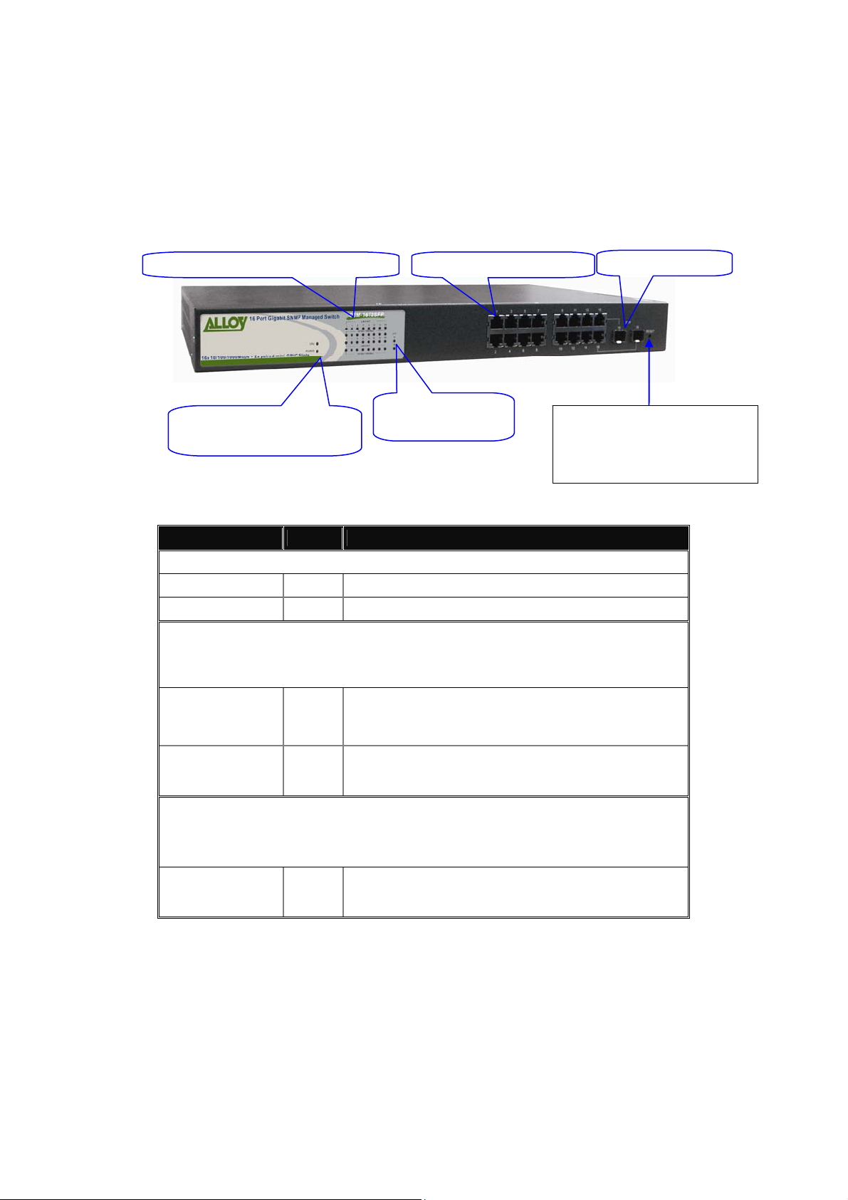
1.4. Overview of GSM Series Switches
Fig. 1-1: Front View of the GSM-16T2SFP Switch
Fig. 1-2: Front View of the GSM-24T2SFP Switch
Fig. 1-3: Front View of the GSM-8T16SFP Switch
5
Alloy Computer Products Pty Ltd Copyright ©2006
GSM Series User Manual
Gigabit
t
Status
catio
s
S
t
1.4.1. User Interfaces on the Front Panel (Button, LED's and Plugs)
There are 16x (GSM-16T2SFP), 24x (GSM-24T2SFP) or 8x (GSM-8T16SFP) copper RJ-45
Gigabit Ethernet ports and 2x SFP fibre ports (GSM-16T2SFP & GSM-24T2SFP) or 16x SFP
fibre ports (GSM-8T16SFP) for optional mini-GBIC modules on the front panel of the switch. The
LED display area, located on the left side of the panel, contains a Power LED (which indicates
the power status of the switch) a CPU LED (which indicates whether the CPU is workin g
correctly) and 8/16/24 LED's that indicate the status of each of the RJ-45 ports on the switch.
There are also 2 or 16 LED’s (depending on model) that indicate the status of each of the SFP
ports.
TP Port
Indi
n LED'
Ethernet Por
FP Fibre Por
LED Indicators
Power Indication LED
& CPU LED
LED Colour Function
Fig. 1-4 : Front View of the GSM-16T2SFP Switch
Fibre Port Status
Indication LED’s
RESET Button:
RESET button is used to
restore the system default
settings.
System LED
POWER
CPU
LEDS for: 10/100/1000Ethernet copper ports 1 to 16 (GSM-16T2SFP)*,
10/100/1000Ethernet copper ports 1 to 24 (GSM-16T2SFP)* or
10/100/1000 Ethernet copper ports 1 to 8 (GSM-8T16SFP)
LINK/ACT
10/100/1000Mbps
LEDS for: SFP Gigabit Fibre Ports 15 & 16 (GSM-16T2SFP)*
SFP Gigabit Fibre Ports 23 & 24 (GSM-24T2SFP)* or
SFP Gigabit Fibre Ports 9 – 24 (GSM-8T16SFP)
SFP(LINK/ACT)
*All SFP ports are paired with one of the 10/100/1000Mbps copper RJ-45 ports. Only
one of the paired ports can be used.
Green Lit when power is active
Green Blinks when CPU is active
- On when connection with remote device is good
Green
Green/
Amber
Green
- Blinks when any traffic is present
- Off when no link is present
- Green when 1000Mbps speed is active
- Amber when 100Mbps speed is active
- Off when 10Mbps speed is active
- On when connection with the remote device is good
- Blinks when any traffic is present
- Off when no link is present
6
Alloy Computer Products Pty Ltd Copyright ©2006
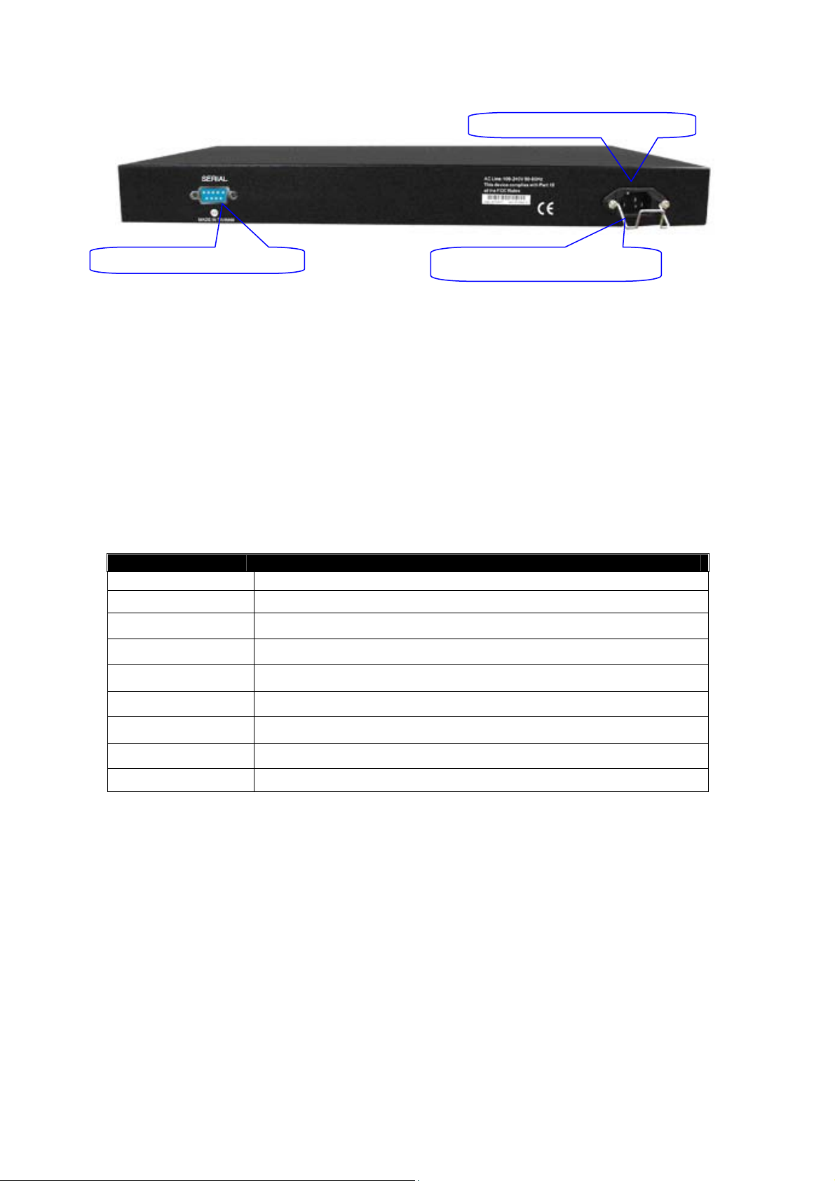
1.4.2. User Interfaces on the Rear Panel
AC
50/60
GSM Series User Manual
RS-232 DB-9 Serial Port
Fig. 1-5: Rear View of the GSM-16T2SFP
AC mains cable locking clamp
Line 100-240V
Hz
1.5. Overview of the Optional SFP Modules
With the GSM-16T2SFP switch, the SFP ports are paired with RJ-45 copper ports 15 and 16. In
the case of the GSM-24T2SFP, the SFP ports are paired with RJ-45 copper ports 23 an d 24.
Only one of any given paired port can be used. In this manner, these paired ports can be seen as
‘Dual Media’ ports that support 10/100/1000Mbps or 1000Mbps fibre via the SFP interfaces.
Unlike the GSM-8T16SFP which has 16 independent SFP ports which could be used as a central
gigabit fibre distribution point.
Optional 1000Mbps mini-GBIC fibre transceiver modules can be used for high-speed uplink
connections to fibre backbones or servers, when installed in the SFP ports. A range of optional
Alloy mini-GBIC modules are available:
Alloy Part No. Description
MGBIC-T 1000Mbps, mini-GBIC, Copper, 100metres
MGBIC-MLC 1000Mbps multimode 1000Base-SX, 850nm, max. range 500m
MGBIC-SLC10 1000Mbps single-mode 1000Base-LX, 1310nm, max. range 10Km
MGBIC-SLC4013 1000Mbps single-mode 1000Base-LHX, 1310nm, max. range 40Km
MGBIC-SLC4015 1000Mbps single-mode 1000Base-LHX, 1550nm, max. range 40Km
MGBIC-SLC70 1000Mbps single-mode 1000Base-ZX, 1550nm, max. range 70Km
MGBIC-SLC100 1000Mbps single-mode 1000Base-EZX, 1550nm, max. range 100Km
MGBIC-WDMS3.20 1000Mbps WDM single-mode/single-fibre 1310nm, max. range 20Km
MGBIC-WDMS5.20 1000Mbps WDM single-mode/single-fibre 1550nm, max. range 20Km
7
Alloy Computer Products Pty Ltd Copyright ©2006

GSM Series User Manual
r
r
Notes: * The two WDM (Wave Division Multiplexer) mini-GBIC modules are
designed to facilitate a link over a single core of single-mode fibre cable.
The two units must be used in a paired manner, one at either end of the link.
* Mini-GBIC modules that are designed to the relevant standards should be
compatible with any make of switch with SFP ports. If you have concerns
regarding compatibility, please contact the supplier of your mini-GBIC
product.
* The information given in the table above is current at time of publication;
availability of individual Alloy mini-GBIC modules may vary over time.
Fig. 1-6: Front View of
1000Base-SX/LX LC,
SFP Fibre Transceive
Fig. 1-7: Front View of
1000Base-LX WDM LC
SFP Fibre Transceive
8
Alloy Computer Products Pty Ltd Copyright ©2006
GSM Series User Manual
2. Installation
2.1. Starting the GSM Series SNMP Managed Switches
This section provides a quick start guide for:
• Hardware and Cable Installation
• Management Station Installation
• Software booting and configuration
2.1.1. Hardware and Cable Installation
Please Note:
⇒ Wear a grounding strap to avoid damaging the switch with an electrostatic discharge
⇒ Be sure that the power switch is in the ‘OFF’ position before you insert the power cord
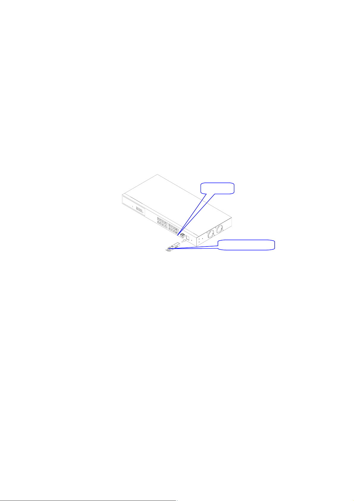
Installing Optional SFP Mini-GBIC Modules
•
SFP port
Fig. 2-1: Installation of optional
SFP mini-GBIC
Mini-GBIC module
• Connecting the SFP Mini-GBIC Module to the Chassis:
The optional SFP Mini-GBIC modules are hot-swappable, so you can plug or unplug them while
the power is applied to the switch.
1. Verify that the mini-GBIC module is compatible with the SFP port on the switch (for example,
some switch manufacturer’s design their mini-GBIC modules to be operable only in their
branded devices).
2. Verify that the type of mini-GBIC you have selected for use will be compatible with the
type of fibre optic cable that is to be used.
3. Verify that the type of mini-GBIC you have selected for use will be compatible with the
fibre optic transceiver at the other end of the link (e.g. – compatible wavelength and
standard).
4. Slide the module along the slot and ensure that the module is properly seated against the
SFP slot socket/connector.
5. Install the media cable for network connection.
6. Repeat the above steps, as needed, for each module to be installed into the switch.
9
Alloy Computer Products Pty Ltd Copyright ©2006

GSM Series User Manual
• Copper Ports - Cable Installation
Please Note:
⇒ The RJ-45 ports on the Alloy GSM Series Switches support MDI/MDI-X auto-crossover
functionality. This enables use of either straight-through or crossover UTP cable
types; the RJ-45 ports will automatically be configured to suit the characteristics of the device
at the remote end of the link.
⇒ The RJ-45 ports on the Alloy GSM Series Switches support Nway auto-negotiation; the
ports will automatically be configured to be compatible with the speed and duplex
settings of the device at the remote end of the link.
⇒ The minimum grade of cable for use with the switch is Cat. 5 grade UTP or STP. Higher
grades of UTP/STP cable may also be used to con nect to the copper RJ-45 ports.
1. Depress the clip on the RJ-45 connector and push into the RJ-45 port. Release
connector and ensure that the cable connector is securely locked into the RJ-45 port.
2. Repeat the above steps, as needed, for each RJ-45 port to be connected.
• Power On
Please Note:
⇒ Alloy GSM Series Switches use a 100-240 VAC, 50-60 Hz power supply. The power supply
will automatically convert your local AC power source to DC power for use by the switch.
1. Ensure that the power switch is turned off before connecting mains power.
2. Connect the power cord supplied with the switch to your nearest mains outlet.
3. Connect the other end of the power cord into the IEC power port on the switch.
4. Lock the power cable into place using the power cable clamp mounted on the IEC power port.
5. Turn the switch on.
6. When initial power is applied, all the LED indicators will light up for a brief period while the
system performs its st art up tests. Once the initial tests (‘POST test’) have complet ed all
except the power and CPU LED should return to an off state.
• Firmware Loading
After power on, the boot-loader will load the switch firmware into the main operational memory.
This process will take about 30 seconds. Once completed, the switch will flash all the LED’s once
and then switch to a ready state.
10
Alloy Computer Products Pty Ltd Copyright ©2006
GSM Series User Manual
2.1.2. Cabling Requirements
To help ensure a successful installation and keep network performance at optimum levels, take
care to use Cat.5e grade or higher cabling. Ensure that stranded core UTP cable, if used, runs
for no more than 10 metres, and that solid core runs for a maximum of 100 metres. Poor cabling
is the most common cause for network dropouts or poor performance.
2.1.2.1. Cabling Requirements for UTP Ports
• For Ethernet copper network connections, the UTP cable used must be Cat. 3 grade as a
minimum, with a maximum length of 100 metres
• For Fast Ethernet copper network connections, the UTP cable used must be Cat. 5 grade as a
minimum, with a maximum length of 100 metres
• For Gigabit Ethernet copper network connection, UTP cable used must be Cat.5 grade or
higher, with a maximum length of 100 metres. Cat.5e grade UTP cable is recommended.
2.1.2.2. Cabling Requirements for 1000SX/LX/ZX SFP Modules
There are two categories of fibre optic modules - multimode (MM) and single-mode (SM). The
later is categorised into several classes by the distance it supports. These are SX, LX, LHX, ZX
and EZX. The majority of mini-GBIC modules available use a LC type connector. The connector
types used currently on Alloy mini-GBIC modules are LC and WDM SC, for the following mod ule
types:
• Gigabit Fibre with multimode LC SFP mini-GBIC modules
• Gigabit Fibre with single-mode LC mini-GBIC modules
• Gigabit Fibre with single-mode/single core WDM SC 1310nm SFP mini-GBIC modules
• Gigabit Fibre with single-mode/single core WDM SC 1550nm SFP mini-GBIC modules
The following table lists the types of fibre optic cable that are supp orted by SFP mini-GBIC
modules installed in Alloy GSM Series Switches. Other cable types not listed here may be
supported; please contact the supplier of your switch for details.
Multimode Fibre Cable and Modal Bandwidth
IEEE 802.3z
Gigabit Ethernet
1000SX 850nm
1000BaseLX/LHX/XD/ZX
1000Base-LX
Single Fibre
(WDM SC)
Multimode 62.5/125μm Multimode 50/125μm
Modal
Bandwidth
160MHz-Km 220m 400MHz-Km 500m
200MHz-Km 275m 500MHz-Km 550m
Single-mode transceiver 1310nm 10Km, 40Km
Single-mode transceiver 1550nm 40Km, 70Km, 100Km
Single-mode
Single-mode
Range
Single-mode Fibre 9/125μm
*20Km
*20Km
Modal
Bandwidth
TX(Transmit) 1310nm
RX(Receive) 1550nm
TX(Transmit) 1550nm
RX(Receive) 1310nm
Range
11
Alloy Computer Products Pty Ltd Copyright ©2006

GSM Series User Manual
Cont. Please Note:
⇒ Further information can be found in section 1.5 on page 7
⇒ All figures denoting the range a given cable type can achieve must be treated as maximum
values. A number of variables can limit the actual range that can be achieved – grade of
cable used, quality of cable, and presence of joins in cable runs, for example
2.1.3. Management options available with the GSM Series Switches
The GSM Series switches support multiple management options to allow administrators to
quickly configure and monitor the switch and network performance. There are four management
options available including RS-232 console, Command Line Interface (CLI), SNMP or via the built
in Web Management. The following procedures will bri efly describe how each method can be
performed and will also be discussed in more detail later in this manual.
Section 2-1-3-1: Configuring the GSM Series switches through the RS-232 serial port.
Section 2-1-3-2: Configuring the GSM Series switches through the Ethernet port.
2.1.3.1. Configuring the GSM Series switches through the RS-232 serial port
When configuring the GSM Series switches via the RS-232 console please connect the switch
via the provided serial cable to a DCE device such as a PC. Once you have connection run a
terminal emulation program such as Hyper Terminal. When connecting to the switch please use
the serial settings of the switch to create the connection, the default settings are below:
Baud Rate: 57600
Data Bits: 8
Parity: None
Stop Bits: 1
Flow Control: None
By pressing Enter you will now be prompted to login to the switch.
The default username and password for the switch is:
Username: admin
Password: admin
The RS-232 console port on the switch is mainly used for the initial setup of the switch including
setting the IP Address, Subnet Mask and Gateway. It is recommended that all other management
duties that need to be performed should be done via the Web Management or CLI.
12
Alloy Computer Products Pty Ltd Copyright ©2006
GSM Series User Manual
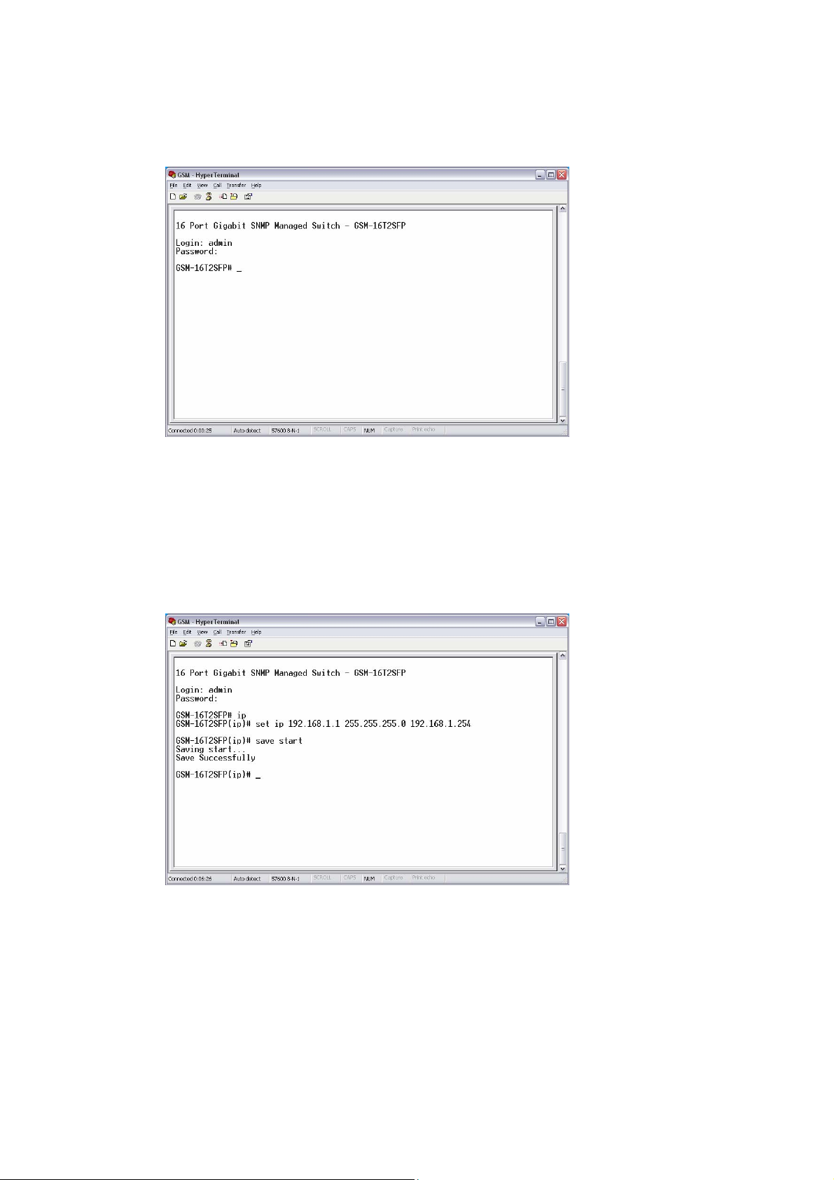
To set or change the default IP address of the switch via the console port, please follow the steps
below:
1. Log into the switch via hyper terminal using the above settings.
2. Type IP and press Enter to enter the IP configuration mode.
3. Type set ip “IP Addre ss” “Subnet Mask” “Gateway” where “IP Address” is the IP
address of the switch, “Subnet Mask” is the subnet mask of the switch and “Gateway” is
the gateway address of the switch, then press Enter.
4. Type save start to save the new switch config uration as the startup configuration for the
switch.
5. Type logout to exit the switch’s management.
Fig. 2-2
Alloy Computer Products Pty Ltd Copyright ©2006
Fig. 2-3
13
GSM Series User Manual
2.1.3.2. Configuring the GSM Series switches through the Ethernet Port
There are three different methods of configuring the GSM Series switches throug h the Ethernet
Port. They are CLI, Web Browser and via SNMP Management Software. We will not cover SNMP
management in this manual as it will vary depending on the Network Management Software that
is being used.
Note: MIB files can be located for each switch on the CD-ROM, which can then be used with your
Network Management Software.
The default IP Address, Subnet Mask and Gateway addresses are shown below:
IP Address: 192.168.1.1
Subnet Mask: 255.255.255.0
Gateway: 192.168.1.254
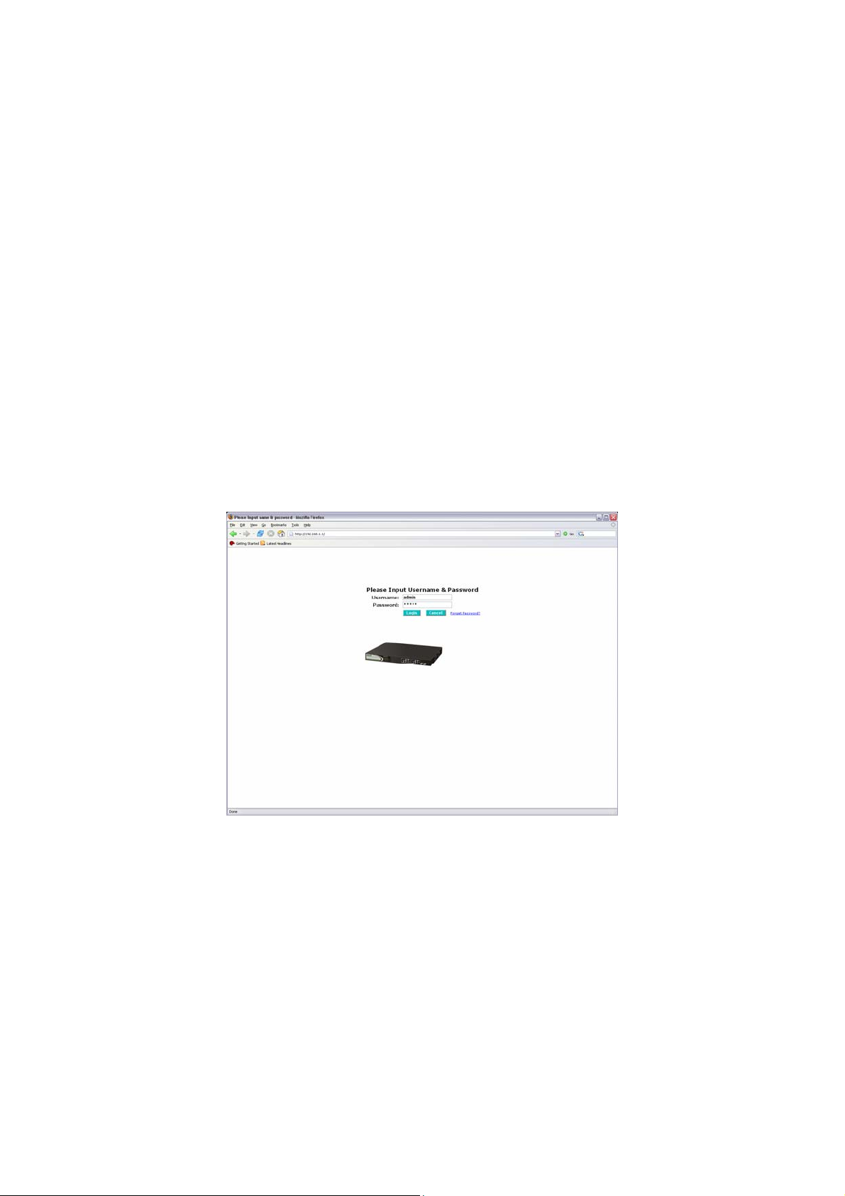
To be able to communicate with the switch via the Ethernet port you will need to ensure that your
computer has an IP Address in the same subnet range.
Eg. 192.168.1.5
If using the web management open a web browser and enter the default IP Address of the switch
into the address bar.
You will now be prompted to log into the switch, the default username and p assword is shown
below:
Username: admin
Password: admin
Fig. 2-4
Note: The web management configuration will be covered in detail in Chapter 3.
14
Alloy Computer Products Pty Ltd Copyright ©2006
GSM Series User Manual
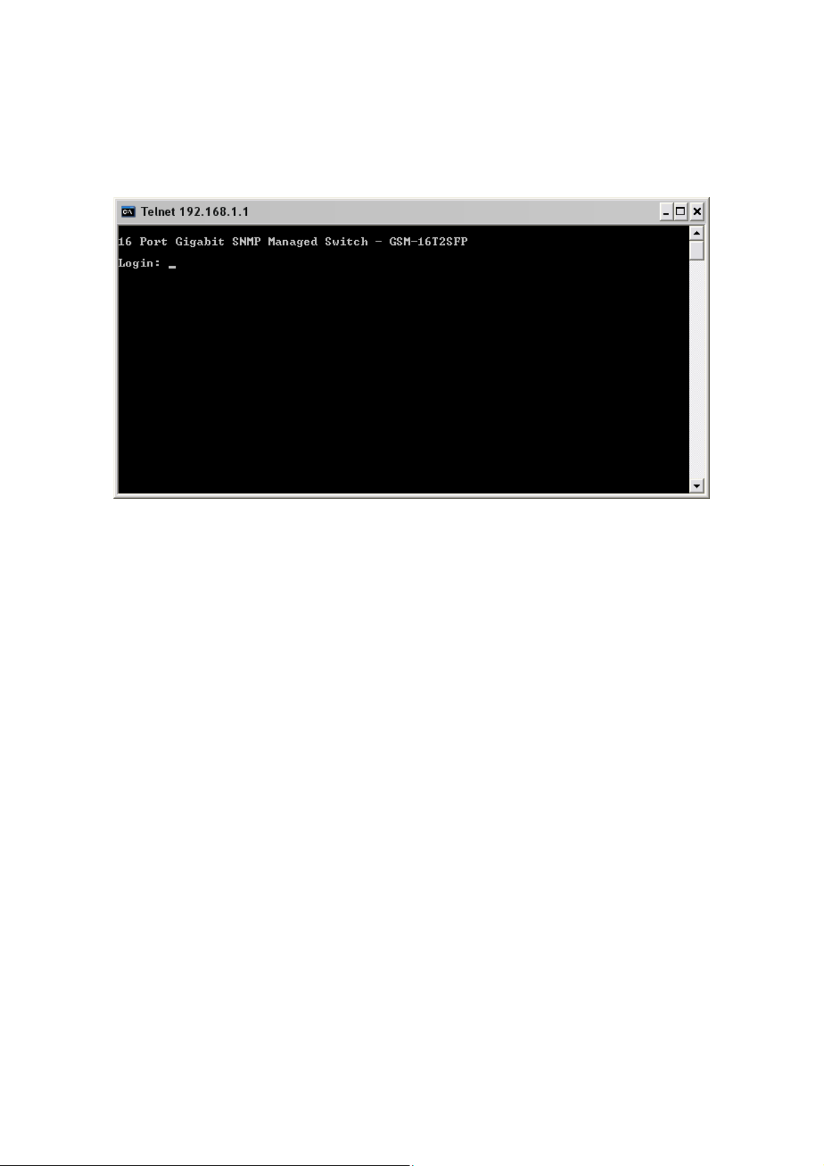
If using the CLI open a command prompt and create a telnet session to the default IP Address of
the switch.
You will now be prompted to log into the switch, the default username and p assword is shown
below:
Username: admin
Password: admin
Note: The CLI configuration will be covered in detail in Chapter 4.
Fig. 2.5
15
Alloy Computer Products Pty Ltd Copyright ©2006
GSM Series User Manual
3. Operation of the Web Based
Management
The following chapter allows the administrator to monitor and manage the GSM Series Switches
through the web management interface. Management functionality such as Port Based and
802.1q VLAN, Port Aggregation (Trunking), QoS, Port configuration and much mo re can all be
configured quickly and easily via any port of the GSM Series switches.
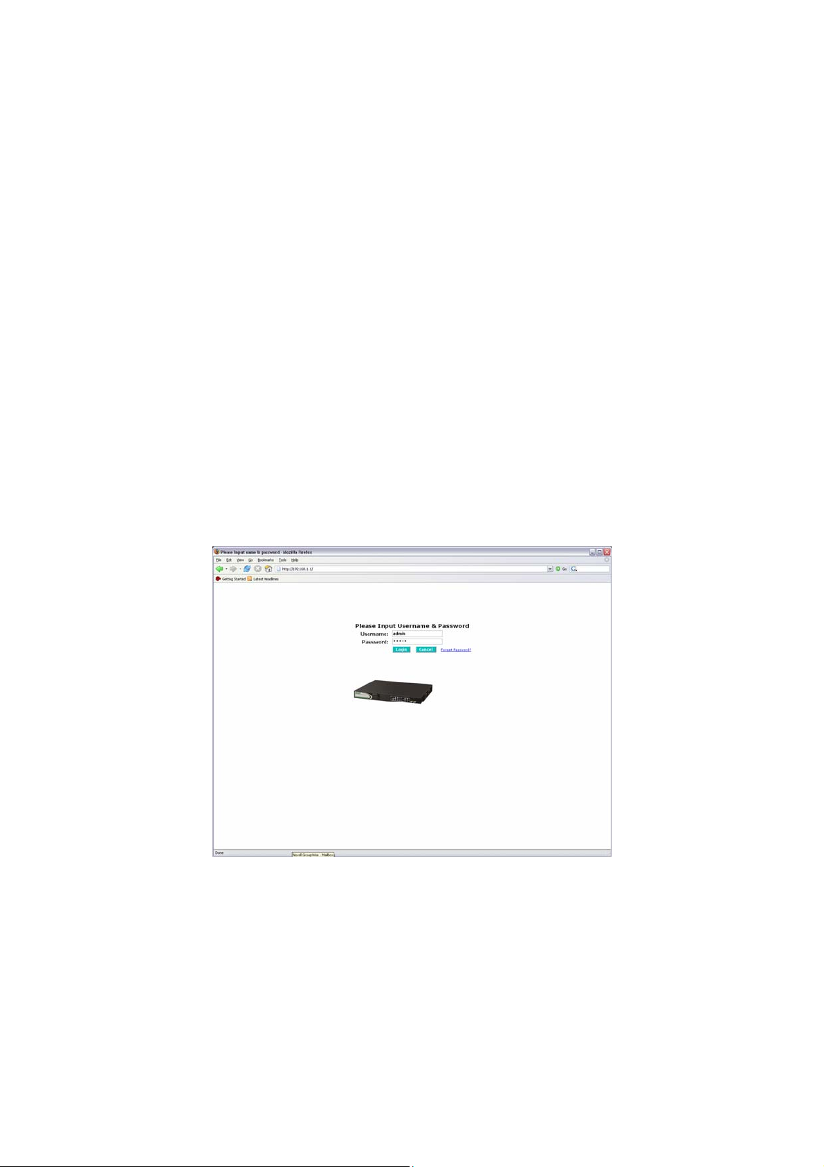
To access the web management of the GSM Series switches open a web browser such as
Internet Explorer or Mozilla Firefox and enter the default IP address into the address bar.
The default network settings for the GSM Series switches are shown below:
IP Address: 192.168.1.1
Subnet Mask: 255.255.255.0
Gateway: 192.168.1.254
Username: admin
Password: admin
Once you have entered the IP address of the GSM Series switch into a web browser you will be
prompted with a login screen where you will need to enter a valid username and pa ssword to
gain access to the switch. The default username and password are shown above.
The GSM Series switches only allow one administrator to configure the switch at one time. If
another user has logged into the switch with the administrator credentials then only the first
admin logged in will be able to configure the switch, the other admin will only be able to monitor
the switch. Other users can also be created to gain access to the switch for monitoring purp oses
only. In total only three users can have access to the web management at any one time.
Fig. 3-1
16
Alloy Computer Products Pty Ltd Copyright ©2006
GSM Series User Manual
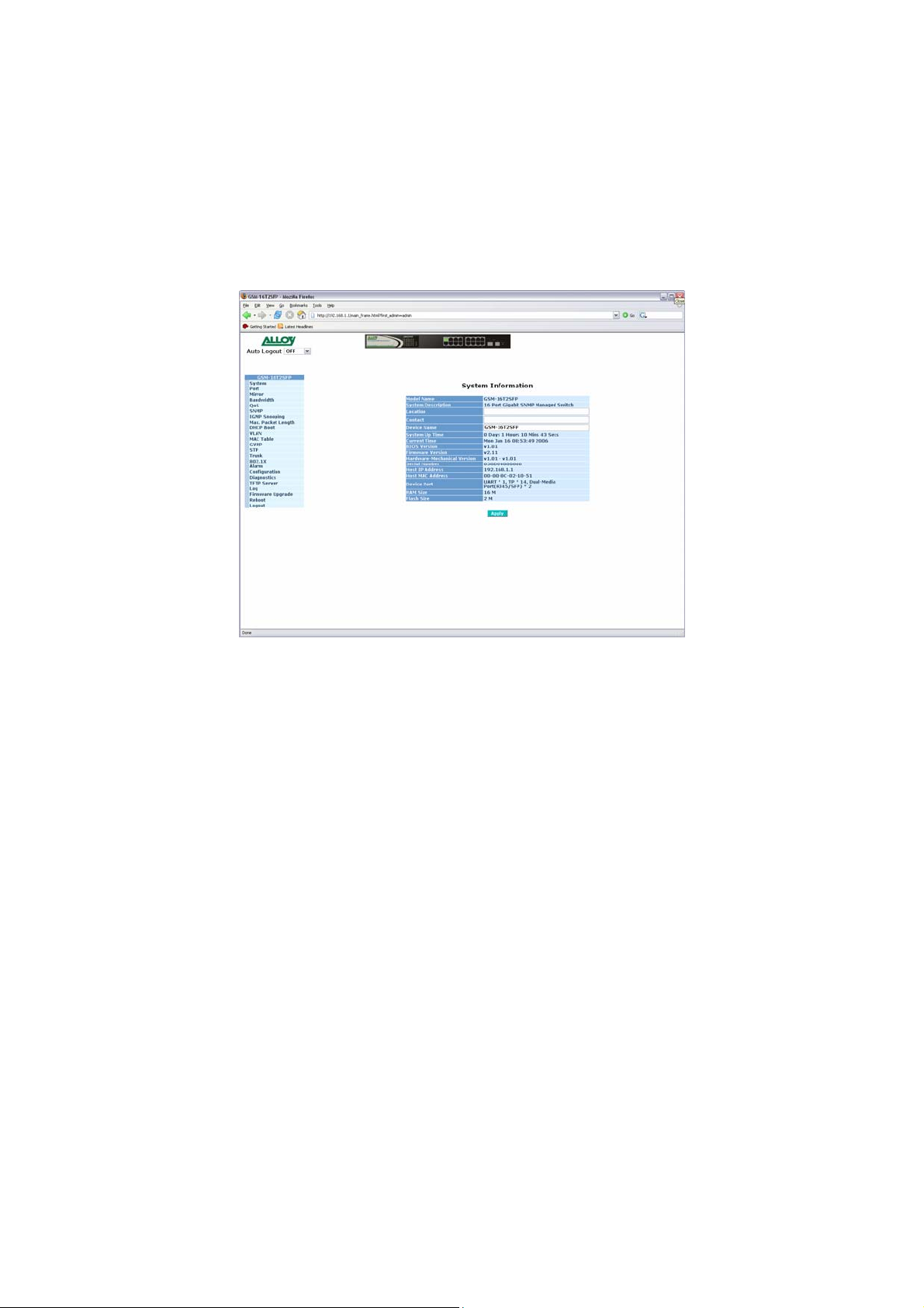
3-1. Web Management Home Overview
Once you have entered a valid username and password and logged into the switch the System
Information page will be displayed, this is the default page, it will be displayed every time that you
log into the switch.
The System Information page gives you all relevant information regarding the switch including,
Model Name, System Description, Location, Contact, Device Name, System Up Time, Current
Time, BIOS Version, Firmware Version, Hardware-Mechanical Version, Serial Number, Host IP
Address, Host MAC Address, Device Port, RAM Size and Flash Size.
Fig. 3-2
17
Alloy Computer Products Pty Ltd Copyright ©2006
GSM Series User Manual
- System Information Page Layout
At the top of the page, there is a picture of the front panel of the switch. The picture displays the
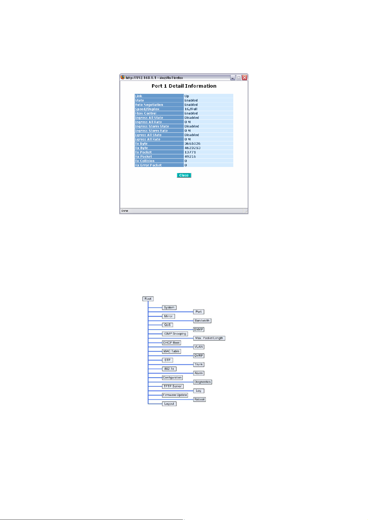
port status of each of the ports on the switch. If the port is green this tells us that the port has an
active connection, if the port is grey then no link is present. You can then click on each of the
ports to give you basic information.
Fig. 3-3
As you can see from the image above, when you click on a particular port, basic information for
that port will be displayed.
At the top left corner of the page is a drop down box that allows the administrator to enable and
set the time out value for the Auto Logou t function. If the switch’s Auto-Logout time is set to 3
minutes, after 3 minutes of no activity the switch will automatically log the user out of the web
interface. The Auto Logout function can also be turned off.
At the left hand side of the screen is the main menu tree. This menu is used to navigate your way
around the switch’s web interface. The image below shows the menu tree for the web interface:
Fig. 3-4
18
Alloy Computer Products Pty Ltd Copyright ©2006
3-1-1. System Information
Allows the Administrator to view basic system settings.
GSM Series User Manual
Fig. 3-5
Function Name:
System Information
Function Description:
Shows the basic system information
Parameter Description:
Model Name:
The model name of the device. (Read Only)
System Description:
Gives you a description of the switch. (Read Only)
Location:
Specify a descriptive location name.
Location name can be up to 36 Alphanumeric Characters long.
Click the <apply> button to update. (Read/Write)
Contact:
Specify the System Administrator.
Contact name can be up to 36 Alphanumeric Characters long.
Click the <apply> button to update. (Read/Write)
Device Name:
Specify a descriptive device name for the switch.
Location name can be up to 36 Alphanumeric Characters long.
Click the <apply> button to update. (Read/Write)
Alloy Computer Products Pty Ltd Copyright ©2006
19

GSM Series User Manual
System Up Time:
The time accumulated since last power up. Format is Day, Hour, Minute, Second.
(Read Only)
Current Time:
Shows the system time of the switch. Format is Day of week, Month, Day, Hours,
Minutes, Seconds, Year. Eg Mon Jan 16 3:46:49 2006 (Read Only)
BIOS Version:
The version of the BIOS in the switch. (Read Only)
Firmware Version:
The firmware version in the switch. (Read Only)
Hardware-Mechanical Version:
The hardware-mechanical version of the switch. (Read Only)
Serial Number:
The serial number assigned to the switch. (Read Only)
Host IP Address:
The IP Address of the switch. (Read Only)
Host MAC Address:
The MAC Address of the switch. (Read Only)
Device Port:
Specifies the port density and types of ports on the switch. (Read Only)
RAM Size:
The size of the DRAM in this switch. (Read Only)
Flash Size:
The size of the flash memory in the switch. (Read Only)
20
Alloy Computer Products Pty Ltd Copyright ©2006
GSM Series User Manual
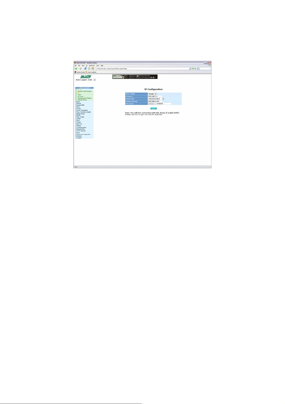
3-1-2. IP Configuration
The IP configuration is used to set the IP settings in the switch. The GSM Series switches
support either a static IP address all ocated to them via the system admini strato r or ca n be
assigned an IP address dynamically from a DHCP server on your network. The IP address is
used to gain access to the management functionality of the switch.
Function Name:
IP Configuration
Function Description:
Is used to set the IP Address, Subnet Mask, Default Gateway and DNS settings for the
switch
Parameter Description:
DHCP Setting:
The GSM Series switches support DHCP (Dynamic Host Configuration Protocol)
Client which is used to receive an IP Address from a DHCP Server running on
your network. By Default the DHCP Client is disabled and a Static IP Address
has been allocated to the GSM Series Switches. If Enabled the switch will
receive an IP Address from an existing DHCP Server on your network. If
Disabled you will need to allocate an IP Address in the spaces provided.
Click the <apply> button to update.
Default: Disabled
IP Address:
If the DHCP settings are set to Disabled you will need to set a manual IP
Address for the switch.
Enter the required IP Address in the space provided.
Click the <apply> button to update.
Fig. 3-6
Default: 192.168.1.1
21
Alloy Computer Products Pty Ltd Copyright ©2006

Subnet Mask:
You will also need to specify a Subnet Mask to be used on your network.
Enter the required Subnet Mask in the space provided.
Click the <apply> button to update.
Default: 255.255.255.0
Default Gateway:
The Default Gateway is used in routed networks to determine the next hop for all
non local destinations.
Enter the required Default Gateway in the space provided.
Click the <apply> button to update.
Default: 192.168.1.254
DNS:
DNS (Domain Name Server) is used to translate between Host Names and IP
addresses. If DHCP has been enabled the switch will receive a DNS IP Address
dynamically from the DHCP Server. If you are not using DHCP you will need to
set a DNS address in the switch. A DNS Server address should be given to you
from your ISP.
Enter the required DNS Server in the space provided.
Click the <apply> button to update.
Default: 0.0.0.0
GSM Series User Manual
22
Alloy Computer Products Pty Ltd Copyright ©2006
GSM Series User Manual
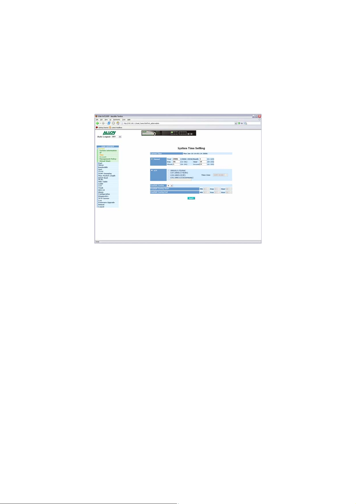
3-1-3. Time Configuration
The GSM Series switches provide two methods to keep the switch’s time settings correct, they
are via manual input and via a Time Server on the internet. If you are manually entering your time
settings enter the “Year”, “Month”, “Day, “Hour”, “Minute” and “Seconds” into the sp ace provided.
If you enter a number that is invalid, for instance you enter 61 in the seconds field it will be
rounded down to the nearest valid number , in this case 59.
If you are using NTP (Network Time Protocol) there are four built in Internet Time Servers that
you can use, or there is a space provided where you can enter a particular Time Server address.
When using NTP you will also need to specify what time zone you are presently located in. The
Time Zone is Greenwich- centered which uses the expression form of GMT +/- xx hours.
Fig. 3-7
Function Name:
Time Configuration
Function Description:
Enter a manual system time or synchronise the GSM Series switch’s time with an
available Internet Time Server. Daylight Saving time adjustment is also supported for
different locations.
Parameter Description:
Current Time:
Shows the current system time.
Manual:
A manual time can b e set into the switch here. Enter the Year,
Month, Day, Hour , Minute and Seconds into the spaces provided. The valid
figures for the parameters Year, Month, Day, Hour, Minute and Seconds are >=
2000, 1 – 12, 1 – 31, 0 – 23, 0 – 59, respectively. Once you have entered the
correct time click the <apply> button to update.
Default: Year 2000, Month = 1, Day = 1, Hour = 0, Minute = 0, Second = 0
Alloy Computer Products Pty Ltd Copyright ©2006
23

NTP:
NTP is used to sync the network time with a time server on the internet based on
the Greenwich Mean Time (GMT). Once the user has selected one of the built in
time servers or entered a manual time server and selected the correct time zone
click the <apply> button to update. The switch will now sync with the sele cted
time server. However thi s synchro nisation doe s not occur periodically if the time
does become out of sync for some unknown reason the administrator will
manually have to click the apply button again to re-sync with the time server.
The Time Zo ne is an offset time of the GMT. The switch supports a configurable
time zone from -12 to +13 hours in increments of 1 hour.
Default: +8 hours
Daylight Savings:
Daylight Savings can be configured from -5 ~ +5 hours in increments of 1 hour. If
your location has adopted daylight savings please enter the appropriate value in
the daylight savings drop down box. If your area does have daylight savings you
will need to enter a starting and ending date of the daylight savings period. Once
the date passes the starting date of the daylight savings settings the switch’s
time will be adjusted by the amount of hours entered in the drop down box.
Click the <apply> button to update.
Default: 0
Default values for starting and ending date:
GSM Series User Manual
Start: Month = 1, Day = 1, Hour = 0
End: Month = 1, Day = 1, Hour = 0
24
Alloy Computer Products Pty Ltd Copyright ©2006
GSM Series User Manual
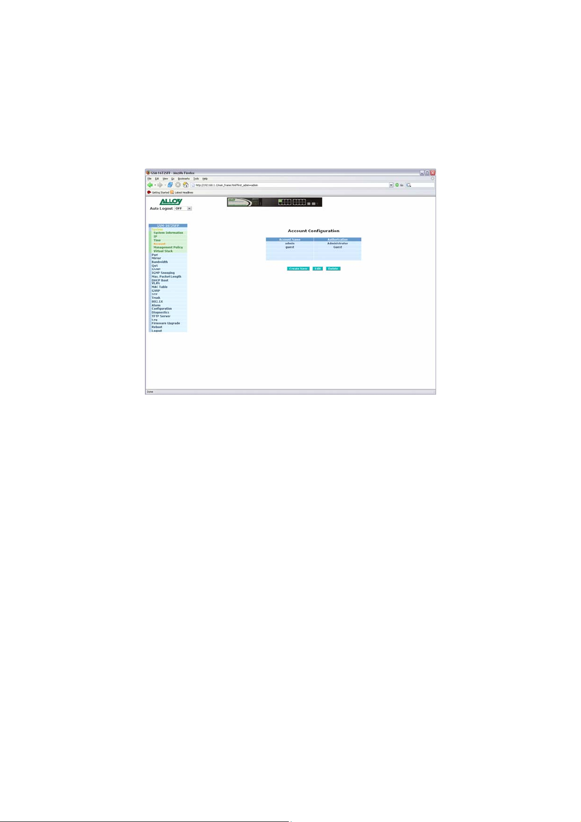
3-1-4. Account Configuration
The account configuration is used to create or modify guest and administrator accounts. The
GSM Series switches allow the administrator to create up to 5 guest accounts, accou nts can only
be created by the administrator. When a Guest user logs into the switch they will not be able to
modify any parameters, they just have read only rights to the switch. A Guest user can log into
the switch and change there own password, but will not be able to modify any other accounts.
The Guest account is purely created for monitoring purposes only. Administrators have the ability
to delete accounts and also change the username and passwords of each account. The
Administrator account can not be deleted.
Fig. 3-8
Function Name:
Account Configuration
Function Description:
Create and Modify Administrator and Guest accounts.
Parameter Description:
Create New:
Click the Create New button to create a new guest account.
Edit:
Click the Edit button to edit an existing account, please ensure that you click on
an account before clicking the Edit button.
Delete:
Select the account that you want to delete and click the Delete button.
Authorisation:
Specifies wha t rights the user has. Only Administrator and Guest accounts can
be created.
25
Alloy Computer Products Pty Ltd Copyright ©2006

Username:
Please enter a username for the administrator or guest account, a maximum of
15 alphanumeric characters only.
Password:
Please enter a password for the administrator or guest account, a maximum of
15 alphanumeric characters only.
Confirm Password:
Please confirm the password.
GSM Series User Manual
26
Alloy Computer Products Pty Ltd Copyright ©2006
 Loading...