

Alloy Computer Products BWS-136 User Manual

BWS-136 User Manual
Alloy Computer Products 22/9/06
BWS-136 User Manual_amend.doc - 1 -
Table of Contents
Introduction.............................................................................................4
LAN.............................................................................................5
Serial ...........................................................................................5
Software ......................................................................................6
Power...........................................................................................6
Environment................................................................................6
Dimension...................................................................................6
Panel Layout........................................................................................7
Connecting Power.......................................................................7
Connecting Ethernet Port ............................................................8
Connecting Serial Port.................................................................8
Switch SW1 Settings...................................................................8
LED Status ................................................................................10
Serial Port Pin Assignments......................................................11
Factory Default Settings............................................................13
Configure BWS-136..................................................................14
Install Java Configuration Utility......................................................15
Serial and Data Packing Settings...............................................17
TCP/IP Network Settings..........................................................17
Device Name Settings...............................................................18
Access Control Settings.............................................................18
Save Configuration....................................................................20
Save Configuration to File.........................................................20
Overview...........................................................................................22
Overview...........................................................................................26
BWS-136 User Manual_amend.doc - 2 -

Serial Console Mode................................................................. 26
Telnet Console Mode................................................................ 27
Command Syntax...................................................................... 28
Echo Syntax.............................................................................. 33
1
Introduction
Overview
BWS-136 provides the easiest way to enable serial industrial device with
networking capability. BWS-136 converts the serial data to standard
TCP/IP protocol therefore the serial device can be accessed everywhere
via Internet or Ethernet. In addition, BWS-136 provides an embedded
Web server which allows user to save the cust om web page t herefore user
can use a standard Web browser to remote manage the serial device.
Package Check List
BWS-136 is shipped with following items:
1. BWS-136 Module
2. Software CD and Electronic user manual
BWS-136 User Manual_amend.doc - 3 -
BWS-136 User Manual_amend.doc - 4 -

Product Specifications
LAN
Ethernet: 10/100 Mbps, RJ45 x1
Protection: Built-in 1500V magnetic isolation
Serial
RS-232/422/485: DB9 connector x1
RS-232 : RxD, TxD, RTS, CTS, DSR, DTR, DCD, GND
RS-422: RX+, RX-, TX+, TX-, GND
RS-485: Data+, Data-, GND
Baud Rate: 300~38400 bps
Parity: None, Even, Odd
Data Bits: 7, 8
Stop Bits: 1, 2
Flow Control: RTS/CTS, XON/XOFF
Protection: 15KV ESD
Digital Input/Output
General Purpose DIO x8
DIO0 to DIO5: Programmable Digital I/O (TTL)
DIO6 to DIO7: Programmable Digital I/O (CMOS)
Software
Protocol: TCP, IP, HTTP, ICMP, DHCP, Telnet,
UDP (only for programming),
Utility: Java Configuration. Web Configuration, Serial Console,
Telnet Console
Operation Mode: TCP Server, TCP Client, Web Control
Power
Power input: 9~40VDC@100mA
Connector: Power Jack or Terminal Block
Environment
Operating Temperature: 0~55°C (32~131°F), 5~95% RH
Storage Temperature: -20~85°C (32~131°F), 5~95% RH
Dimension
108x78x25 mm (HxWxD) without ear
BWS-136 User Manual_amend.doc - 5 -
BWS-136 User Manual_amend.doc - 6 -
2
Getting Started
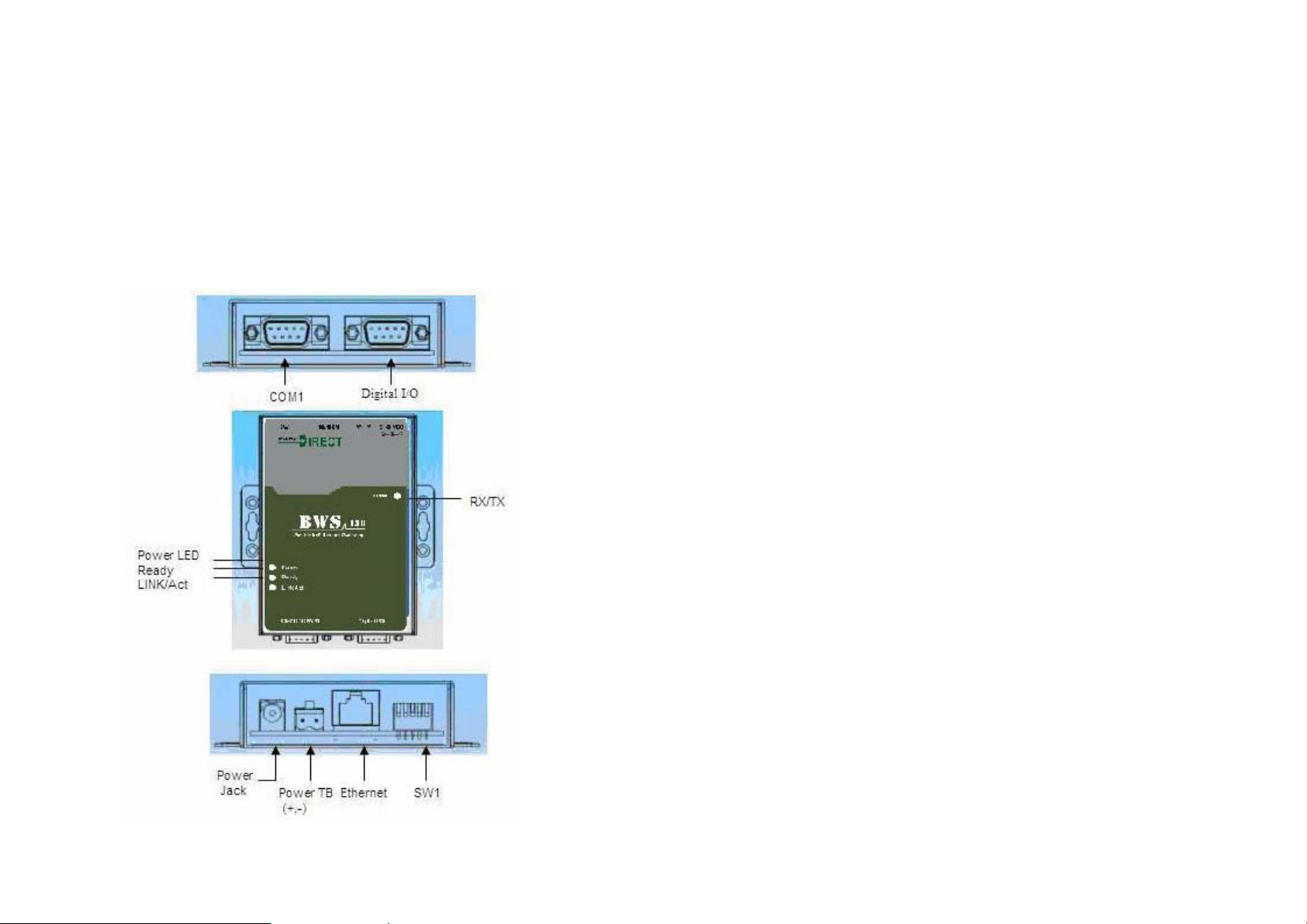
Connecting 9~40VDC power line with the BWS-136 terminal
block or the power jack. If the power is properly supplied, the
Power LED will keep solid yellow color.
Panel Layout Connecting
Power
Connecting Ethernet Port
Connect a RJ45 Ethernet cable to the Ethernet port of BWS-136.
The Link/Activity light will keep solid yellow color if Ethernet
cable is corrected to the network and this light will keep flashing if
there are data transmitted.
Connecting Serial Port
Use a null modem DB9 serial cable to connect a RS232 serial
device to BWS-136 serial port. The null modem cable will cross
over the RxD to TxD connection between the serial device to
Aport 211.
Switch SW1 Settings
Set the SW1 setting to RS-232 mode and pin definition of Aport
211 serial port is as follow:
BWS-136 User Manual_amend.doc - 7 -
BWS-136 User Manual_amend.doc - 8 -

SW1 Setting:
SW1 Key 1 2 3 4 5
RS-232 ON OFF OFF - RS-422 OFF OFF OFF - RS-485 OFF ON ON - Normal - - - OFF OFF
DHCP OFF ON
Default ON OFF
Console ON ON
Normal: Aport is in Normal Operation Mode
DHCP: Network IP Address is assigned by DHCP Server
Default: All the settings are reset to Factory Default.
Console: COM1 serial port is served as console port. User can
use ACSII command to configure BWS-136 via COM1 port.
Please refer to Appendix I for the ASCII command
Changing the switch settings will not be effective until
system reboot by pressing RESET button
LED Status
The LED provides the BWS-136 operation information. The
LED status is described as follow:
Power LED: Power LED keeps ON if power (+9VDC to +40VDC)
is correctly input to BWS-136.
Ready LED: Ready LED keeps ON when Aport 211 firmware is
ready for operation. Ready LED will be flash when Aport 211 in
Serial Console mode (SW1 key 4 and key 5 are ON) or Telnet
Console mode (Telnet Console port:5001 are connected)
Link/Act LED: Link and Activity LED will turn ON when the
Ethernet cable is connected. When there is network data traffic,
this LED will be flash.
RX/TX LED: The RX/TX LED is a dual color LED that indicates
the serial data traffic. In RS-232 mode, the Yellow LED stands
for transmitting data and Green LED means receiving data. In
RS-422/485 mode, the Yellow LED stands for receiving data and
Green LED means transmitting data.
BWS-136 User Manual_amend.doc - 9 -
BWS-136 User Manual_amend.doc - 10 -
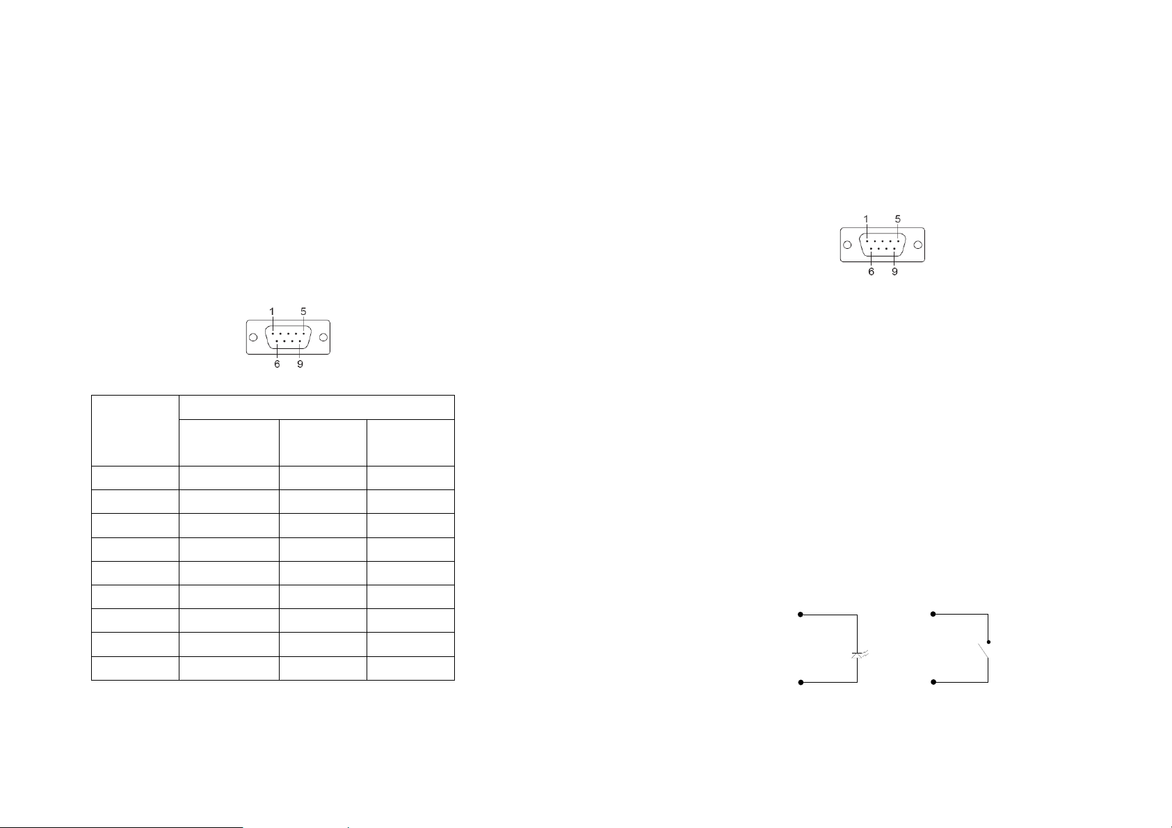
Serial Port Pin Assignments
Serial Port COM1 uses a Male DB9 connector and it includes
RS-232, RS-422 and RS485 signal and pin assignments are
described as follow:
Pin
Number
1 DCD TxD- 2 RxD TxD+ 3 TxD RxD+ Data+
4 DTR RxD- Data5 GND GND GND
6 DSR - 7 RTS - 8 CTS - -
RS-232 4-wire
Transmission Signals
RS-485
RS485
Digital I/O
Digital I/O uses DB9 connector and the pin assignments
are described as follow:
Pin 1: DIO4
Pin 2: DIO3
Pin 3: DIO2
Pin 4: DIO1
Pin 5: DIO0
Pin 6: GND
Pin 7: DIO7
Pin 8: DIO6
Pin 9: DIO5
DIO0 to DIO5 are TTL compatible Programmable
DIO and DIO 6 to DIO7 are CMOS compatible Programmable DIO.
All the DIO channel are pull up +5VDC with a 4.7K Ohm resistor.
DIO
As an Output
DIO
As an Input
9 - - -
BWS-136 User Manual_amend.doc - 11 -
GND
BWS-136 User Manual_amend.doc - 12 -
GND
 Loading...