


NetEnforcer
AC-1000 Series
Policy Based Bandwidth Management
Hardware Guide
P/N D362001 R2


Important Notice
Important Notice
Allot Communications Ltd. ("Allot") is not a party to the purchase agreement under which NetEnforcer was purchased, and
will not be liable for any damages of any kind whatsoever caused to the end users using this manual, regardless of the form of
action, whether in contract, tort (including negligence), strict liability or otherwise.
SPECIFICATIONS AND INFORMATION CONTAINED IN THIS MANUAL ARE FURNISHED FOR
INFORMATIONAL USE ONLY, AND ARE SUBJECT TO CHANGE AT ANY TIME WITHOUT NOTICE, AND
SHOULD NOT BE CONSTRUED AS A COMMITMENT BY ALLOT OR ANY OF ITS SUBSIDIARIES. ALLOT
ASSUMES NO RESPONSIBILITY OR LIABILITY FOR ANY ERRORS OR INACCURACIES THAT MAY APPEAR IN
THIS MANUAL, INCLUDING THE PRODUCTS AND SOFTWARE DESCRIBED IN IT.
Please read the End User License Agreement and Warranty Certificate provided with this product before using the product.
Please note that using the products indicates that you accept the terms of the End User License Agreement and Warranty
Certificate.
WITHOUT DEROGATING IN ANY WAY FROM THE AFORESAID, ALLOT WILL NOT BE LIABLE FOR ANY
SPECIAL, EXEMPLARY, INDIRECT, INCIDENTAL OR CONSEQUENTIAL DAMAGES OF ANY KIND,
REGARDLESS OF THE FORM OF ACTION WHETHER IN CONTRACT, TORT (INCLUDING NEGLIGENCE),
STRICT LIABILITY OR OTHERWISE, INCLUDING, BUT NOT LIMITED TO, LOSS OF REVENUE OR
ANTICIPATED PROFITS, OR LOST BUSINESS, EVEN IF ADVISED OF THE POSSIBILITY OF SUCH DAMAGES.
Copyright
Copyright © 1997-2007 Allot Communications. All rights reserved. No part of this document may be reproduced,
photocopied, stored on a retrieval system, transmitted, or translated into any other language without a written permission and
specific authorization from Allot Communications Ltd.
Trademarks
Products and corporate names appearing in this manual may or may not be registered trademarks or copyrights of their
respective companies, and are used only for identification or explanation and to the owners' benefit, without intent to infringe.
Allot and the Allot Communications logo are registered trademarks of Allot Communications Ltd.
NOTE: This equipment has been tested and found to comply with the limits for a Class A digital device, pursuant to Part 15 of
the FCC Rules. These limits are designed to provide reasonable protection against harmful interference when the equipment
is operated in a commercial environment. This equipment generates, uses, and can radiate radio frequency energy and, if not
installed and used in accordance with the instruction manual, may cause harmful interference to radio communications.
Operation of this equipment in a residential area is likely to cause harmful interference in which case the user will be
required to correct the interference at his own expense.
Changes or modifications not expressly approved by Allot Communication Ltd. could void the user's authority to operate the
equipment.
AC-1000 Series Hardware Guide
iii

Important Notice
Printing History
First Edition: July, 2006
Second Edition: September, 2007
AC-1000 Series Hardware Guide
iv

Table of Contents
Important Notice .......................................................................................................................... iii
Printing History ............................................................................................................................. iv
Table of Contents ........................................................................................................................... v
Table of Figures ........................................................................................................................... vii
CHAPTER 1: AC-1000 SERIES HARDWARE ......................................................... 1-1
AC-1000 Series Packing List ..................................................................................................... 1-2
NetEnforcer Front Panel ........................................................................................................... 1-3
AC-1000 Series Front Panels ................................................................................................... 1-4
LCD Panel ................................................................................................................................ 1-6
Power Supply Modules ............................................................................................................. 1-8
Accessories Area .................................................................................................................... 1-11
Cabling ...................................................................................................................................... 1-14
AC-1000 Series Copper .......................................................................................................... 1-14
AC-1000 Multi Mode (SX) Fiber ........................................................................................... 1-16
AC-1000 Series Single Mode (LX5, LX20, ZX) Fiber .......................................................... 1-17
Connectors .............................................................................................................................. 1-18
Bypass Units .............................................................................................................................. 1-19
AC-1010 Bypass Units ........................................................................................................... 1-19
AC-1020 Bypass Unit ............................................................................................................. 1-23
AC-1040 Bypass Unit ............................................................................................................. 1-28
Powering Up ............................................................................................................................. 1-30
Connection to AC Power ........................................................................................................ 1-30
Connection to DC Power ........................................................................................................ 1-30
Grounding ............................................................................................................................... 1-31
Powering Up Via LCD Panel ................................................................................................. 1-32
CHAPTER 2: PLACEMENT IN THE NETWORK .................................................. 2-1
CHAPTER 3: SETTING UP THE NETENFORCER ................................................ 3-1
Configuring Via a Terminal or Telnet ...................................................................................... 3-1
NetEnforcer AC-1000 Hardware Guide
v

Configuring Via the LCD Panel .............................................................................................. 3-12
CHAPTER 4: REDUNDANCY .................................................................................... 4-1
Enabling Redundancy ................................................................................................................ 4-1
Parallel Redundancy ................................................................................................................ 4-13
Status Indicators in Parallel Redundancy Mode ..................................................................... 4-14
Secondary NetEnforcer Activation ......................................................................................... 4-15
Active Redundancy ................................................................................................................... 4-17
Failover ................................................................................................................................... 4-17
Policy Configuration ............................................................................................................... 4-17
Connecting the NetEnforcer in Active Redundancy ............................................................... 4-18
Active Redundancy for the AC-1020 ...................................................................................... 4-18
Active Redundancy for the AC-1040 ...................................................................................... 4-18
Serial Redundancy .................................................................................................................... 4-19
NetEnforcer Failover............................................................................................................... 4-20
Serial Redundancy in Mesh Topologies ................................................................................. 4-21
CHAPTER 5: HARDWARE SPECIFICATIONS ..................................................... 5-1
Dimensions ............................................................................................................................... 5-1
Power Requirements ................................................................................................................. 5-1
Operating Environment ............................................................................................................. 5-2
Standards, Compliance and Certifications ............................................................................... 5-3
CHAPTER 6: FIREWALL PORT REFERENCE ..................................................... 6-1
CHAPTER 7: ÉQUIPEMENT DE SÉRIE AC-1000 ................................................. 7-1
Mises en garde d’ordre général: ................................................................................................ 7-2
Remarques d’ordre général: ...................................................................................................... 7-4
Spécifications matérielles ........................................................................................................... 7-5
Dimensions ............................................................................................................................... 7-5
Spécifications requises .............................................................................................................. 7-5
vi
NetEnforcer AC-1000 Hardware Guide

Table of Figures
Figure
Figure
Figure
Figure
Figure
Figure
Figure
Figure
Figure
Figure
Figure
Figure
1-1 – Front Panel: AC-1000 Series ................................................................................... 1-3
1-2 – Front Panel: AC-1010 Copper ................................................................................. 1-4
1-3 – Front Panel: AC-1020 Fiber .................................................................................... 1-4
1-4 – Front Panel: AC-1040 Copper ................................................................................. 1-5
1-5 – NetEnforcer LCD Panel .......................................................................................... 1-6
1-6 – Dual SC Connector (Multi Mode Fiber) ................................................................ 1-18
1-7 – Dual LC Connector (Single Mode Fiber) .............................................................. 1-18
1-8 – Single Copper Bypass Unit ................................................................................... 1-19
1-9 – Connecting the NetEnforcer AC-802 Copper to the Single Copper Bypass Unit . 1-20
1-10 –Single Fiber Bypass Unit – Multi Mode ............................................................... 1-21
1-11 –Single Fiber Bypass Unit – Single Mode ............................................................. 1-21
1-12 – Connecting NetEnforcer AC-1010 Fiber to Single Fiber Bypass Unit – Multi Mode
............................................................................................................................................ 1-22
Figure
Figure
1-13 – Connecting the NetEnforcer AC-1020 to Double Copper Bypass Unit .............. 1-24
1-14 – Double Fiber Bypass Unit - MultiMode .............................................................. 1-25
Figure
Figure
1-15 – Double Fiber Bypass Unit – Single Mode ........................................................... 1-26
1-16 – Connecting the NetEnforcer AC-1020 to Double Fiber Bypass Unit – Single Mode
............................................................................................................................................ 1-27
Figure
Figure
NetEnforcer AC-1000 Hardware Guide
1-17 – Multi-Port Copper Bypass Unit ........................................................................... 1-28
3-1 – NetEnforcer Setup Menu ......................................................................................... 3-2
vii

Figure 3-2 – Current Configuration (1) ........................................................................................ 3-4
Figure
Figure
Figure
Figure
Figure
Figure
Figure
Figure
Figure
Figure
Figure
Figure
Figure
Figure
3-3 – Current Configuration (2) ........................................................................................ 3-5
3-4 – Network Configuration ............................................................................................ 3-6
3-5 – Password .................................................................................................................. 3-9
3-6 – Time Setup ............................................................................................................. 3-10
4-1 – NIC Tab AC-1010 – NetXplorer Configuration ...................................................... 4-3
4-2 – Networking Tab AC-1010 – NetXplorer Configuration .......................................... 4-4
4-3 – NIC Tab AC-1020 – NetXplorer Configuration ...................................................... 4-7
4-4 – Networking Tab AC-1020 – NetXplorer Configuration .......................................... 4-8
4-5 – NIC Tab AC-1040 – NetXplorer Configuration .................................................... 4-11
4-6 – Networking Tab AC-1040 – NetXplorer Configuration ........................................ 4-12
4-7 – Serial Redundancy – Normal Scenario .................................................................. 4-19
4-8 – Serial Redundancy – Failover Scenario ................................................................. 4-20
4-9 – Serial Redundancy – Bypass Scenario ................................................................... 4-21
4-10 – Serial Redundancy – Mesh Scenario ................................................................... 4-22
viii
NetEnforcer AC-1000 Hardware Guide

Chapter 1: AC-1000 Series Hardware
This chapter describes the NetEnforcer AC-1000 series hardware and the initial
installation and setup of the device. The NetEnforcer is a transparent learning bridge
that is IEEE 802.1-compliant and works with a Bypass Unit to ensure that data
continues flowing should any hardware or software problem occur. While the
NetEnforcer is bypassed, all traffic goes through passive elements only and still allows
the network to function.
NetEnforcer AC-1000 series offers carrier-grade design with redundant critical
components for fail-safe operation. Redundant hardware components include system
fans and dual hot-swappable power supplies. The NetEnforcer AC-1000 series is
designed to meet ETSI standards.
All AC-1000 series units come with an additional Bypass Unit.
CAUTION All AC-1000 Series models only function when the appropriate
Bypass Unit is connected to it. This is to ensure continuous service
in the event of failure.
NOTE AC-1000 NetEnforcer NIC default factory setting is always Auto-
Negotiation enabled, with the exception of the AC-1010 Copper whose
default NIC setting is 1000 full, Auto-Negotiation disabled.
It is recommended to keep the NetEnforcer’s default setting. Changing
NIC settings is done via LCD panel only.
Several NetEnforcer models are available to support large and small sites and different
data network speeds.
All NetEnforcer AC-1000 series units support 1M connections (2M flows), 2,000 pipes
and 8,000 Virtual Channels. Additional Pipes and Virtual Channels can also be
purchased separately per device. Allot basic management software is included with all
AC-1000 series devices. Allot NetXplorer Centralized Management software can be
purchased for any AC-1000 series device using software version S7.1.0 or later,
replacing the basic management.
NetEnforcer AC-1000 Hardware Guide
1-1

Chapter 1: AC-1000 Series Hardware
The NetEnforcer AC-1010 is a general-purpose carrier grade device with one line (two
port) connectivity. The device is available with either AC or DC power supplies and
with copper, SX fiber, LX5 fiber, LX20 fiber or ZX fiber interface connectors. The AC1010 may be ordered with an upgradable throughput of 155 Mbps, 310 Mbps, 622
Mbps or 1 Gbps.
The NetEnforcer AC-1020 is intended to be used in a mesh network configuration
where redundancy is kept by connecting each path to a different network device. The
AC-1020 has two line (four port) connectivity. The device is available with either AC or
DC power supplies and with copper, SX fiber, LX5 fiber, LX20 fiber or ZX fiber
interface connectors. The AC-1020 may be ordered with an upgradable throughput of
155 Mbps, 310 Mbps, 622 Mbps, 1 Gbps or 2 Gbps.
The NetEnforcer AC-1040 is a carrier grade unit intended for large service providers or
carriers with four line (eight port) connectivity. The unit is available with either AC or
DC power supplies and with copper interface connectors. The AC-1040 is provided
with a non-upgradable throughput of 400 Mbps,
AC-1000 Series Packing List
Verify that the following items are included with NetEnforcer:
• NetEnforcer (hardware with pre-installed software)
• NetEnforcer Hardware Guide
• Two mains power cables according to National Electrical Code (NEC) with
molded IEC sockets
• 1 Serial Console Cable
• 1 Ethernet Cross Management Cable
• 2 19" Side Mounting Brackets
• 8 Mounting Bracket Screws
• 1 D-type High Density Backup Cable
NOTE The maximum Ethernet cable length is generally up to 50 meters.
1-2
NetEnforcer AC-1000 Hardware Guide

Chapter 1: AC-1000 Series Hardware
NetEnforcer Front Panel
The AC-1000 series connects to your network via Link Connection connectors. The
LCD panel, connectors and LED indicators on the front panel, are shown in the
following diagrams.
The front panel of each AC-1000 series unit is separated into four areas as shown
below:
Figure
1-1 – Front Panel: AC-1000 Series
The front panel of NetEnforcer is laid out as follows:
• LCD panel, described on page 1-6
• The Link Connections area
• Power Supply Modules, described on page 1-8.
• Accessory area, including the following:
• Management Port, described on page 1-11
• Management LEDs, described on page 1-12
• Console Connector described on page 1-12
• Backup High Density D-type Connector (see Bypass Units on page 1-
19)
• Two power cable connectors described on page 1-13.
NetEnforcer AC-1000 Hardware Guide
1-3

Chapter 1: AC-1000 Series Hardware
AC-1000 Series Front Panels
AC-1010 Front Panels
Figure
AC-1020 Front Panel
1-2 – Front Panel: AC-1010 Copper
Figure
1-4
NetEnforcer AC-1000 Hardware Guide
1-3 – Front Panel: AC-1020 Fiber

Chapter 1: AC-1000 Series Hardware
AC-1040 Front Panels
Figure
CAUTION CLASS 1 LASER PRODUCT. DANGER!
1-4 – Front Panel: AC-1040 Copper
Invisible laser radiation when opened.
AVOID DIRECT EXPOSURE TO BEAM.
NetEnforcer AC-1000 Hardware Guide
1-5

Chapter 1: AC-1000 Series Hardware
LCD Panel
The NetEnforcer LCD panel provides an indication of traffic usage and enables you to
configure NetEnforcer directly without the need to connect a terminal. You can also
start, reboot and shutdown NetEnforcer from the front panel.
Display Area
Display Area
Standby Indicator
Standby Indicator
Up Arrow
Up Arrow
Left A rrow
Left A rrow
Down Arro w
Down Arro w
Figure
Ri ght Arrow
Ri ght Arrow
On/Off Enter
On/Off Enter
Sel ec t
Sel ec t
1-5 – NetEnforcer LCD Panel
Active Indicator
Active Indicator
P ower Indicator
P ower Indicator
For a description of how to configure NetEnforcer using the LCD panel, refer to
Configuring Via the LCD Panel, page 3-12.
For a description of the Standby, Active and Power LEDs, refer to Interface Status
Indicators, page 1-8.
1-6
NetEnforcer AC-1000 Hardware Guide

Chapter 1: AC-1000 Series Hardware
Unit Status Indicators
The modes of operation of the Standby, Active and Power LEDs on the LCD panel are
described in the table below.
Indicator Status NetEnforcer Status
Standby
Off This NetEnforcer is the primary system. If you have one
On Two NetEnforcers are connected in Parallel Redundancy
mode and this NetEnforcer is the secondary system.
NetEnforcer, this should be the normal state of the LED. If
you have two NetEnforcers configured in Parallel
Redundancy mode, this NetEnforcer is the primary system.
Active
Off NetEnforcer is in Bypass mode, or this is the secondary
Power
Off NetEnforcer is shut down.
Table 1-1 – Standby/Active/Power LED Conditions
On NetEnforcer is in Active mode.
NetEnforcer in a Parallel Redundancy configuration and it
is not active. Traffic passes through NetEnforcer with no
Quality of Service or traffic shaping.
On NetEnforcer is powered up.
NetEnforcer AC-1000 Hardware Guide
1-7

Chapter 1: AC-1000 Series Hardware
Interface Status Indicators
The modes of operation of the Link (External and Internal) LEDs are described in the
table below.
Link Status Indicators – AC-1010/1020
Ext/Int LED NetEnforcer Status
Green
A lit green LED indicates that a link is detected.
Amber
Off
Table 1-2 – External/Internal LED Conditions – AC-1010/1020
Link Status Indicators – AC-1040
Ext/Int LED NetEnforcer Status
Green
Red
Off
Table 1-3 – External/Internal LED Conditions – AC-1040
A blinking amber LED indicates that traffic is detected on
the interface.
An unlit LED indicates that neither links nor activities were
detected.
A lit green LED indicates that a link is detected.
A blinking red LED indicates that traffic is detected on the
interface.
An unlit LED indicates that neither links nor activities were
detected.
Power Supply Modules
NetEnforcer includes two hot-swappable power supply modules and a dual line feed for
Redundancy purposes. Each line feed is driving one power supply.
1-8
NetEnforcer AC-1000 Hardware Guide

Chapter 1: AC-1000 Series Hardware
NOTE The AC power supply automatically adapts to voltages between 100 V and
240 V, 50/60 Hz. The DC power supply automatically adapts to voltages
of 48 V or 60 V DC.
This equipment is for use in a restricted access area by qualified
personnel only. To avoid shock, do not perform any servicing other than
those contained in the unpacking instructions.
Should you need to, you can replace one of the power supplies while NetEnforcer is
connected and operating. Replacing a power supply while the unit is operating is
possible since the remaining power supply will take the full load and maintain full
operation.
NOTE To remove a power supply module, undo the two screws in the lower left
and right corners, lift the handle and slide the module out.
NetEnforcer AC-1000 Hardware Guide
1-9

Chapter 1: AC-1000 Series Hardware
Each power supply has two LEDs located beneath the power supply handles.
Model Copper/Fiber options Power inlet options
AC 1010 Transceiver SFP Copper
Transceiver SFP SX
Transceiver SFP LX 5
Transceiver SFP LX 20
Transceiver SFP ZX
AC 1020 Transceiver SFP Copper
Transceiver SFP SX
Transceiver SFP LX 5
Transceiver SFP LX 20
Transceiver SFP ZX
AC 1040 Copper AC/DC
AC/DC
AC/DC
CAUTION The power entry modules (AC supply option) include two fuses (T2A
250 V, 5 x 20 mm) at each power entry. One is a spare fuse for
replacement purposes. You can open the fuse box and change when
necessary. For continued protection against risk of fire, replace only
with same type and rating of fuse.
Disconnect the product from the power line before removing the
cover. Any adjustment and maintenance of the opened device
should be done only while the device is disconnected from its
source of power and should only be performed by qualified
personnel
1-10
NetEnforcer AC-1000 Hardware Guide

Chapter 1: AC-1000 Series Hardware
Accessories Area
Management Port (Out of Band Management)
Out-of-band management provides the following:
• Offers physical separation between shaped traffic and management traffic.
• Enables access to NetEnforcer even if there is a problem in the network (for
example, DoS attack).
• Prevents management traffic from interfering with shaped traffic.
• Permits NetEnforcer management from a DMZ.
The NetEnforcer includes a dedicated Management port for out-of-band management of
the device. The dedicated Management port provides a secure solution for device
management for enterprise and service providers. It enables you to permit access solely
to a closed group of network administrators, so that ISP customers cannot "see" the
Management port and therefore cannot access the NetEnforcer management. Operating
through the Management port denies management access to the device from Internal or
External ports. Moreover, when there is a problem in the regular network, for example,
a DoS (Denial of Service) attack, you can still manage and monitor the NetEnforcer.
Using a Management port has the following benefits:
• Provides a security feature that prevents ISP customers from "seeing" the
Management port and thus prevents access to NetEnforcer. The Internal and
External ports are functioning solely to forward traffic, consequently only the
administrator (the only one who has access to the Management port) has
access to NetEnforcer.
• Enables configuring, installing and upgrading while the unit is in Bypass
mode. This is particularly important when NetEnforcer is in carrier
environments.
• Improves NetEnforcer's forwarding performance by separating the
management traffic from the regular traffic. In addition, if a problem exists in
the regular network you can still communicate with NetEnforcer in order to
repair the problem.
NetEnforcer AC-1000 Hardware Guide
1-11

Chapter 1: AC-1000 Series Hardware
• Provides an infrastructure for improvement of the redundancy capabilities.
NOTE The Management port has its own MAC and IP address.
Management Port Status Indicators
Management Port Status Indicators – AC-1010/1020
The modes of operation of the Management port LEDs are described in the table below.
Mgmnt LED NetEnforcer Status
Green
A lit green LED indicates that a link is detected.
Amber
Off
Table 1-4 –Management LED Conditions – AC-1010/1020
Management Port Status Indicators – AC-1040
Mgmnt LED NetEnforcer Status
Green
Red
Off
Table 1-5 –Management LED Conditions – AC-1040
A blinking amber LED indicates that traffic is detected on
the interface.
An unlit LED indicates that neither links nor activities were
detected.
A lit green LED indicates that a link is detected.
A blinking red LED indicates that traffic is detected on the
interface.
An unlit LED indicates that neither links nor activities were
detected.
Console Port
The Console Port allows the connection of a PC to the NetEnforcer in order to monitor
or configure the unit via the Command Line Interface (CLI)
1-12
NetEnforcer AC-1000 Hardware Guide

Chapter 1: AC-1000 Series Hardware
Power Cable Connectors
The unit power cables (AC or DC) plug in here. The power cables should not be
removed while swapping the power modules.
CAUTION This equipment has a connection between the earthed conductor of the DC
supply circuit and the earthing conductor. Before connecting the product to
the power line, make sure that the protective ground terminal of the device is
connected to the safety ground conductor of the mains power cord. The
mains plug should only be inserted in a socket outlet provided with a
connected safety ground. The protective action must not be negated by use
of an extension cord (power cable) without a protective conductor
(grounding). Any interruption of the protective (grounding) conductor or
disconnection of the protective ground terminal can make the device unsafe
to use. Intentional interruption is prohibited.
NetEnforcer AC-1000 Hardware Guide
1-13

Chapter 1: AC-1000 Series Hardware
Cabling
AC-1000 Series Copper
NOTE Ethernet Cables may be Straight or Cross, depending upon your network.
Shielded cables must be used in order to insure compliance.
Connections Cable Type Connector Type
To NetEnforcer
Management Port
To NetEnforcer Console
Port
Primary NetEnforcer
Internal/Eternal to
Bypass Unit
Internal/External
Secondary NetEnforcer
Internal/External to
Network
NetEnforcer Backup
Connector to Bypass
Unit
Bypass Unit Internal to
Switch
Bypass Unit External to
Router
Ethernet (Cat-6) (Included,
P/N C411011)
Ethernet (Cat-6) (Included,
P/N C002005B)
Ethernet (Cat 6) (Included,
P/N C411008 x2)
Ethernet (Cat 6) RJ-45
DB-9 Cable (Included, P/N
C002009)
Ethernet (Cat 6) RJ-45
Ethernet (Cat 6) RJ-45
RJ-45
RJ-45
RJ-45
D-Type 9-Pin/26-Pin
1-14
NetEnforcer AC-1000 Hardware Guide

Chapter 1: AC-1000 Series Hardware
NetEnforcer AC-1000 Hardware Guide
1-15

Chapter 1: AC-1000 Series Hardware
AC-1000 Multi Mode (SX) Fiber
NOTE Ethernet Cables may be Straight or Cross, depending upon your network.
Connections Cable Type Connector Type
To NetEnforcer
Management Port
To NetEnforcer Console
Port
Primary NetEnforcer to
Bypass Unit
(Internal/External)
NetEnforcer Backup
Connector to Bypass
Unit
Secondary NetEnforcer
to Network
(Internal/External)
Bypass Unit Internal to
Switch
Bypass Unit External to
Router
Ethernet (Cat-6) (Included,
P/N C411011)
Ethernet (Cat-6) (Included,
P/N C002005B)
Built In Built In
DB-9 Cable (Included,
P/N C002009)
62.5/125μ fiber optic cable
62.5/125μ fiber optic cable
62.5/125μ fiber optic cable Dual SC
RJ-45
RJ-45
D-Type 9-Pin/26-Pin
Dual SC
Dual SC
1-16
NetEnforcer AC-1000 Hardware Guide

Chapter 1: AC-1000 Series Hardware
AC-1000 Series Single Mode (LX5, LX20, ZX) Fiber
NOTE Ethernet Cables may be Straight or Cross, depending upon your network.
Connections Cable Type Connector Type
To NetEnforcer
Management Port
To NetEnforcer Console
Port
Primary NetEnforcer to
Bypass Unit
(Internal/External)
NetEnforcer Backup
Connector to Bypass
Unit
Secondary NetEnforcer
to Network
(Internal/External)
Bypass Unit Internal to
Switch
Bypass Unit External to
Router
Ethernet (Cat-6) (Included,
P/N C411011)
Ethernet (Cat-6) (Included,
P/N C002005B)
9/125μ fiber optic cable
(Included, P/N C411015)
DB-9 Cable (Included,
P/N C002009)
9/125μ fiber optic cable
9/125μ fiber optic cable
9/125μ fiber optic cable Dual LC
RJ-45
RJ-45
Dual LC
D-Type 9-Pin/26-Pin
Dual LC
Dual LC
NetEnforcer AC-1000 Hardware Guide
1-17

Chapter 1: AC-1000 Series Hardware
Connectors
NetEnforcer Bypass Units using Multi Mode fiber (SX) utilize dual SC Connectors.
Figure
NetEnforcer Bypass Units using Single Mode fiber (LX5, LX20 and ZX) utilize dual
LC connectors.
1-6 – Dual SC Connector (Multi Mode Fiber)
Figure
NOTE Color and appearance of actual connectors may vary.
1-7 – Dual LC Connector (Single Mode Fiber)
1-18
NetEnforcer AC-1000 Hardware Guide

Chapter 1: AC-1000 Series Hardware
Bypass Units
The AC-1000 series operates with an external Bypass Unit. The Bypass Unit is a
mission-critical subsystem designed to ensure network connectivity at all times. The
Bypass mechanism provides "connectivity insurance" in the event of a NetEnforcer
subsystems failure.
NetEnforcer is supplied with a Bypass Unit appropriate to the Unit. The AC-1010 Fiber
operates with a Fiber Bypass and the AC-1010 Copper operates with a Copper Bypass.
The AC-1020 Fiber operates with a Double Fiber Bypass and the AC-1020 Copper
operates with a Double Copper Bypass. The AC-1040 operates with a Multi-port
Copper Bypass.
CAUTION A NetEnforcer AC-1000 unit must be connected to the appropriate
Bypass Unit. This is to ensure continuous service in the event of
failure.
A separate NetEnforcer Bypass package is included with your AC-1000 series
shipment.
AC-1010 Bypass Units
Single Copper Bypass Unit
The Single Copper Bypass Unit works in conjunction with NetEnforcer AC-802 Copper
models.
Figure
NOTE Use UTP CAT-6 straight Ethernet cables to connect link connections
NetEnforcer AC-1000 Hardware Guide
1-8 – Single Copper Bypass Unit
marked with Internal and External labels. The maximum Ethernet cable
length is generally 50 meters.
1-19

Chapter 1: AC-1000 Series Hardware
The Single Copper Bypass Unit includes RJ-45 connectors for Ethernet cables and two
D-type 9-pin connectors for primary and redundant unit to backup connection.
The following procedure describes how to connect a Single Copper Bypass Unit to
NetEnforcer.
To External
Router
To Internal
Switch
Figure
1-9 – Connecting the NetEnforcer AC-802 Copper to the Single Copper
Bypass Unit
To connect the Single Copper Bypass to the NetEnforcer:
NOTE For important information regarding cable and connector types, see
Cabling on page 1-14.
Connect the External cable from the External port on the Bypass Unit
1.
to the External port on NetEnforcer.
2. Connect the Internal cable from the Internal port on the Bypass Unit, to
the Internal port on NetEnforcer.
1-20
NetEnforcer AC-1000 Hardware Guide

Chapter 1: AC-1000 Series Hardware
3. Connect the D-type connector from the Primary port on the Bypass
Unit, to the Backup port on NetEnforcer. The 9-pin connector is
plugged into the bypass unit and the 26 pin connector is plugged into
the NetEnforcer.
4. Connect the External cable from the External port on the Bypass Unit,
to a router connector.
5. Connect the Internal cable from the Internal port on the Bypass Unit, to
a switch connector.
NOTES To connect a secondary NetEnforcer for Parallel Redundancy, you need
two NetEnforcers and one Bypass Unit.
Internal and external connectors of the redundant NetEnforcer should be
connected directly to the network. There is no need to connect via the
Bypass Unit.
Single Fiber Bypass Unit
The Single Fiber Bypass Unit works in conjunction with NetEnforcer AC-1010 Fiber.
There are two different Single Fiber Bypass units, one for Multi Mode connections (SX
fiber) and one for Single Mode (LX5, LX20 and ZX fiber).
Figure
Figure
NetEnforcer AC-1000 Hardware Guide
1-10 –Single Fiber Bypass Unit – Multi Mode
1-11 –Single Fiber Bypass Unit – Single Mode
1-21

Chapter 1: AC-1000 Series Hardware
NOTE Use 62.5/125μ or 9/125μ fiber optic cables with dual LC connectors (not
provided) to connect 1 Gbps ports of the switch and the router.
The Single Fiber Bypass Unit includes either two duplex LC connectors and one built in
fiber cable (for Multi Mode connections) or two quad LC connectors (for Single Mode
connections), along with two D-type 9-pin connectors for primary and redundant unit to
backup connection.
The following procedure describes how to connect a Single Fiber Bypass Unit to
NetEnforcer.
To External
Router
To Internal
Switch
Figure
1-12 – Connecting NetEnforcer AC-1010 Fiber to Single Fiber Bypass Unit
– Multi Mode
To connect the Single Fiber Bypass to NetEnforcer:
NOTE For important information regarding cable and connector types, see
Cabling on page 1-14.
1-22
NetEnforcer AC-1000 Hardware Guide

Chapter 1: AC-1000 Series Hardware
1. Connect the fiber cable labeled External from the Bypass Unit, to the External port
on NetEnforcer.
2. Connect the fiber cable labeled Internal from the Bypass Unit, to the Internal port
on NetEnforcer.
3. Connect the D-type connector from the Primary port on the Bypass Unit, to the
Backup port on NetEnforcer. The 9-pin connector is plugged into the bypass unit
and the 26 pin connector is plugged into the NetEnforcer.
4. Connect a 62.5/125μ or 9/125μ External fiber optic cable from the External port on
the Bypass Unit, to a 1 Gbps router.
5. Connect a 62.5/125μ or 9/125μ Internal fiber optic cable from the Internal port on
the Bypass Unit, to a 1 Gbps switch.
NOTES To connect a secondary NetEnforcer for Parallel Redundancy, you need
two NetEnforcers and one Bypass Unit.
Internal and external connectors of the redundant NetEnforcer should be
connected directly to the network. There is no need to connect via the
Bypass Unit.
AC-1020 Bypass Unit
Double Copper Bypass Unit
The Double Copper Bypass Unit works in conjunction with NetEnforcer AC-1020
Copper.
NOTE Use UTP CAT-6 straight Ethernet cables to connect link connections
marked with Internal and External labels. The maximum Ethernet cable
length is generally 50 meters.
The Double Copper Bypass Unit includes RJ-45 connectors for Ethernet cables and
D-type 9-pin connectors for primary and redundant unit to backup connection.
NetEnforcer AC-1000 Hardware Guide
1-23

Chapter 1: AC-1000 Series Hardware
The following procedure describes how to connect a Double Copper Bypass Unit to
NetEnforcer AC-1020.
To External
Router
To Internal
Switch
Figure
1-13 – Connecting the NetEnforcer AC-1020 to Double Copper Bypass Unit
To connect the Double Copper Bypass to the NetEnforcer:
NOTE For important information regarding cable and connector types, see
Cabling on page 1-14.
Connect the External cable from the To NetEnforcer External port (Link 1) on the
1.
Bypass Unit to the External port on the NetEnforcer (Link 1).
2. Connect the Internal cable from the To NetEnforcer Internal port (Link 1) on the
Bypass Unit to the Internal port on NetEnforcer (Link 1).
3. Connect the External cable from the External port on the Bypass Unit, to a router
(1000Base-T) connector.
1-24
NetEnforcer AC-1000 Hardware Guide

Chapter 1: AC-1000 Series Hardware
4. Connect the Internal cable from the Internal port on the Bypass Unit, to a switch
connector.
5. Repeats Steps 1 to 4 for Link 2.
6. Connect the D-type High Density connector from the Primary port on the Bypass
Unit, to the Backup port on NetEnforcer. The 9-pin connector is plugged into the
bypass unit and the 26 pin connector is plugged into the NetEnforcer.
NOTES To connect a secondary NetEnforcer for Parallel Redundancy, you need
two NetEnforcers and one Bypass Unit.
Internal and external connectors of the redundant NetEnforcer should be
connected directly to the network. There is no need to connect via the
Bypass Unit.
Double Fiber Bypass Unit
The Double Fiber Bypass Unit works in conjunction with NetEnforcer AC-1020 Fiber.
There are two different Double Fiber Bypass units, one for Multi Mode connections
(SX fiber) and one for Single Mode (LX5, LX20, ZX fiber).
Figure
NetEnforcer AC-1000 Hardware Guide
1-14 – Double Fiber Bypass Unit - MultiMode
1-25

Chapter 1: AC-1000 Series Hardware
Figure
NOTE Use 62.5/125μ or 9/125μ fiber optic cables with dual LC connectors (not
1-15 – Double Fiber Bypass Unit – Single Mode
provided) to connect 1 Gbps ports of the switch and the router.
The Double Fiber Bypass Unit includes connectors for connecting to Link 1 and Link 2
on the AC-1020. The Link Connectors area includes either two duplex LC connectors,
and one built in fiber cable (for Multi Mode connections) or two quad LC connectors
(for Single Mode connections) for each link. In addition, the Double Fiber Bypass Unit
includes two D-type 9-pin connectors for primary and redundant unit to backup
connection.
1-26
NetEnforcer AC-1000 Hardware Guide

Chapter 1: AC-1000 Series Hardware
The following procedure describes how to connect a Double Fiber Bypass Unit to
NetEnforcer AC-1020.
To External
Router
Figure
1-16 – Connecting the NetEnforcer AC-1020 to Double Fiber Bypass Unit –
Single Mode
To connect the Double Fiber Bypass to the NetEnforcer:
To Internal
Switch
NOTE For important information regarding cable and connector types, see
Cabling on page 1-14.
Connect the fiber cable labeled To NetEnforcer External (Link 1) from the Bypass
1.
Unit to the External port on the NetEnforcer (Link 1).
2. Connect the fiber cable labeled To NetEnforcer Internal (Link 1) from the Bypass
Unit to the Internal port on the NetEnforcer (Link 1).
3. Connect a 62.5/125μ or 9/125μ External fiber optic cable from the External (link 1)
port on the Bypass Unit to a 1 Gbps router.
NetEnforcer AC-1000 Hardware Guide
1-27

Chapter 1: AC-1000 Series Hardware
4. Connect a 62.5/125μ or 9/125μ Internal fiber optic cable from the Internal port on
the Bypass Unit to a 1 Gbps switch.
5. Repeats Steps 1 to 4 for Link 2.
6. Connect the D-type High Density connector from the Primary port on the Bypass
Unit, to the Backup port on the Primary NetEnforcer. The 9-pin connector is
plugged into the bypass unit and the 26 pin connector is plugged into the
NetEnforcer.
NOTES To connect a secondary NetEnforcer for Parallel Redundancy, you need
two NetEnforcers and one Bypass Unit.
Internal and external connectors of the redundant NetEnforcer should be
connected directly to the network. There is no need to connect via the
Bypass Unit.
AC-1040 Bypass Unit
Multi-Port Copper Bypass Unit
The Multi-port Copper Bypass Unit works in conjunction with the NetEnforcer AC1040 Copper.
Figure
NOTE Use UTP CAT-6 straight Ethernet cables to connect link connections
1-17 – Multi-Port Copper Bypass Unit
marked with Internal and External labels. The maximum Ethernet cable
length is generally 50 meters.
The Copper Bypass Unit includes RJ-45 connectors for Ethernet cables and D-type
9-pin connectors for primary and redundant unit to backup connection.
1-28
NetEnforcer AC-1000 Hardware Guide

Chapter 1: AC-1000 Series Hardware
The following procedure describes how to connect the Bypass Unit to NetEnforcer
AC-1040.
To connect the Bypass Unit to the NetEnforcer AC-1040:
NOTE For important information regarding cable and connector types, see
Cabling on page 1-14.
1.
Connect the External cable from the To NetEnforcer External port (Link 1) on the
Bypass Unit to the External port on NetEnforcer (Link 1).
2. Connect the Internal cable from the To NetEnforcer Internal port (Link 1) on the
Bypass Unit to the Internal port on NetEnforcer (Link 1).
3. Connect the External cable from the External port on the Bypass Unit to a router
(100Base-T) connector.
4. Connect the Internal cable from the Internal port on the Bypass Unit, to a switch
connector.
5. Repeats Steps 1 to 4 for Link 2 to 4.
6. Connect the D-type High Density connector from the Primary port on the Bypass
Unit to the Backup port on NetEnforcer. The 9-pin connector is plugged into the
bypass unit and the 26 pin connector is plugged into the NetEnforcer.
NOTES To connect a secondary NetEnforcer for Parallel Redundancy, you need
two NetEnforcers and one Bypass Unit.
Internal and external connectors of the redundant NetEnforcer should be
connected directly to the network. There is no need to connect via the
Bypass Unit.
NetEnforcer AC-1000 Hardware Guide
1-29

Chapter 1: AC-1000 Series Hardware
Powering Up
Connection to AC Power
Power supply cords are intended to serve as the disconnect device. The user can power
down the device only by removing the two-power cords from the power source or the
device itself.
Make sure the wall socket outlet is installed near the equipment and that the socket is
easy to access. It is recommended that the wall socket outlet be connected to the
building installation protection.
When connecting NetEnforcer to 120 / 240 VAC supply, plug into 10 A service
receptacles, type N5/10 or NEMA 5-10R. Ensure that each site has a suitable ground.
Ground all metal racks, enclosures, boxes and raceways. The NetEnforcer equipment
should be reliably grounded through the power supply cord.
Connection to DC Power
CAUTION Use a UL listed 10A circuit breaker between a centralized DC power
system and the NetEnforcer power entry module.
Before performing the following procedure, ensure that power is removed from DC
circuit.
1. Verify that power is off to the DC-input circuit.
2. Wire the DC-input power supply to the terminal block, ensuring that all
wire connections are secure (suggested DC-input wires are 14-AWG
copper UL listed conductors:
• Ground wire to the ground connector (you should always connect the ground
wire first and disconnect it last).
• -48V wire to the - connector.
• -48V return to the + connector.
1-30
NetEnforcer AC-1000 Hardware Guide

Chapter 1: AC-1000 Series Hardware
3. Restore power to the DC circuit by turning the circuit breaker on (|). Do
not restore power until you are ready to boot the NetEnforcer system.
This unit is intended for RESTRICTED ACCESS LOCATIONS in accordance with
NEC (National Electric Code) or the authority having jurisdiction. Power supply cable
comprises two sets of 3x14 AWG copper wires; use UL-listed cable only.
When connecting NetEnforcer to 48/60 V , use a UL-listed 10A circuit breaker between
the centralized DC power system and NetEnforcer power entry module as the
disconnect device incorporated in the fixed wiring. The circuit breaker must beclose to
the NetEnforcer and easily accessible.
CAUTION A two-pole 10A circuit breaker must be used between the unit and
the centralized DC power source.
The DC supply source is to be located within the same premises as this equipment.
There shall be no switching or disconnecting devices in the grounded circuit conductor
between the DC source and the point of connection of the grounding electrode
conductor.
CAUTION DC Unit Grounding: Before connecting the product to the power line,
make sure that the protective ground terminal of the device is
connected to the safety ground conductor of the mains power cord.
The mains plug should only be inserted in a socket outlet provided
with a connected safety ground. The protective action must not be
negated by use of an extension cord (power cable) without a
protective conductor (grounding). Any interruption of the protective
(grounding) conductor or disconnection of the protective ground
terminal can make the device unsafe to use. Intentional interruption
is prohibited.
This equipment has a connection between the earthed conductor of
the DC supply circuit and the earthing conductor.
Grounding
All NetEnforcer equipment has a connection between the grounded conductor of the DC
supply circuit and the grounding conductor.
NetEnforcer AC-1000 Hardware Guide
1-31

Chapter 1: AC-1000 Series Hardware
Connect to a reliably grounded SELV source. Grounding is achieved through
connection of the power entry module grounding terminal to one power port of the
terminal block by min. No. 14 AWG green/yellow conductor.
This equipment shall be connected directly to the DC supply system grounding
electrode conductor or to a bonding jumper from grounding terminal bar or bus to
which the DC supply system grounding electrode is connected. When connecting the
supply wires to the DC main supply, the earth conductor will be connected first and
disconnected last.
This equipment shall be located in the same immediate area (such as, adjacent cabinets
or any other equipment that has a connection between the grounded conductor of the
same DC supply circuit and the grounding conductor, and also the point of grounding of
the DC system. The DC system shall not be grounded elsewhere.
Powering Up Via LCD Panel
NOTE The NetEnforcer and the Bypass Unit have to be fully plugged and
connected before power is turned on. This is to ensure proper and
systematic power up.
It is recommended to connect the two power line feeds to separate power sources to
have full power redundancy. The two bi-color Power LEDs on the rear of NetEnforcer
are lit indicating that the power supply is connected to power and no failure condition
exists.
The Power LED on the LCD panel is lit and the Mode LED on the Bypass Unit is off,
indicating that the power is on and NetEnforcer is bypassed.
The display area of the LCD panel indicates the following: Power On.
After a few seconds, the display area of the LCD panel indicates the following:
System Loading *.
Once the system has completed loading, the following occurs:
The Active LED on the LCD panel is lit and the Mode LED on the Bypass Unit is lit,
meaning that NetEnforcer is now connected to the network.
1-32
NetEnforcer AC-1000 Hardware Guide

Chapter 1: AC-1000 Series Hardware
The display area of the LCD panel indicates the default view - the current bandwidth
consumption. For example:
Inbound: XXX.X
Outbound: YYY.Y
You can now proceed to configure NetEnforcer, as required.
NetEnforcer AC-1000 Hardware Guide
1-33


Chapter 2: Placement in the Network
The NetEnforcer is normally placed on the internal side of your access router. The
Internal port of the NetEnforcer interfaces with your Local Area Network (LAN) and
the External port of the NetEnforcer interfaces with your access router.
To connect NetEnforcer to your network:
1. Connect the Bypass Unit to NetEnforcer, as described in Bypass Units,
page 1-8.
2. Connect the LAN side of your network to the Internal connector of each link on the
front panel of the Bypass Unit.
3. Connect the cable connected to the WAN side of your network to the External
connector of each link on the front panel of the Bypass Unit.
NOTE For important information regarding cable and connector types, see
Cabling on p. 1-8.
Power up NetEnforcer. Refer to Powering Up, page 1-30.
4.
NetEnforcer AC-1000 Hardware Guide
2-1


Chapter 3: Setting Up the NetEnforcer
In order to manage and configure NetEnforcer policies remotely from your Web
browser or NetXplorer centralized management software, several basic parameters must
be configured on NetEnforcer. You can configure these basic parameters using a
terminal connected to NetEnforcer or by using the LCD panel.
Configuring Via a Terminal or Telnet
You can use a standard terminal /PC running terminal emulation software connected to
the Console port, or Telnet via the internet to configure a NetEnforcer. If you choose to
connect via the Console port, most standard windows-based PC systems have a terminal
emulation program called HyperTerminal that can be used for this purpose. Configure
the terminal to run VT100 terminal emulation with the following parameters:
• Baud rate 19200
• 8 bits
• Stop bits 1
• No flow control
• No parity
NetEnforcer AC-1000 Hardware Guide
3-1

Chapter 3: Setting Up the NetEnforcer
To connect a terminal to the NetEnforcer:
1. Use the supplied serial cable to connect the terminal to the Console Connector on
the front panel of the NetEnforcer.
2. Connect the power cable and power up NetEnforcer, as described in Powering Up,
page 1-30.
3. At the terminal, select Start > Programs > Accessories and double-click on the
HyperTerminal icon. Enter a name for the session and then to set the com port
and the parameters (see above). The system boots up and you are prompted for a
login and a password.
4. Enter admin for the login and allot for the password. (To change the password, see
page 3-9.)
5. Press <Enter>. The NetEnforcer Setup Menu is displayed:
Figure
3-2
NetEnforcer AC-1000 Hardware Guide
3-1 – NetEnforcer Setup Menu

Chapter 3: Setting Up the NetEnforcer
To connect to a NetEnforcer via Telnet:
1. Open a Microsoft DOS window on a PC and at the C:\ prompt, enter
Telnet (IP address of NetEnforcer). Press <Enter>. The system boots
up and you are prompted for a login and a password.
2. Enter admin for the login and allot for the password. (To change the
password, see page 3-9.)
Press <Enter>. The NetEnforcer Setup Menu is displayed:
NetEnforcer Start Menu
From this menu, you can perform the following tasks:
• Display the current configuration, page 3-4.
• Configure network parameters, page 3-6.
• Change the login password, page 3-9.
• Modify the date and time settings, page 3-10.
• Reboot and Shutdown the unit, p 3-16.
NetEnforcer AC-1000 Hardware Guide
3-3

Chapter 3: Setting Up the NetEnforcer
Displaying the Current Configuration
You can display and view the currently set network configuration parameters at any
time.
To display the current configuration:
1. In the NetEnforcer Setup Menu, enter 1 (List current configuration) and
press <Enter>. The current network configuration parameters are
displayed. A sample screen is shown below:
Figure
2. Press <Enter> to show the second screen of parameters:
3-4
NetEnforcer AC-1000 Hardware Guide
3-2 – Current Configuration (1)

Chapter 3: Setting Up the NetEnforcer
Figure
3-3 – Current Configuration (2)
3. Press <Enter> to return to the NetEnforcer Setup Menu.
NetEnforcer AC-1000 Hardware Guide
3-5

Chapter 3: Setting Up the NetEnforcer
Configuring Network Parameters
You can define network parameters manually.
To define network parameters manually:
1. In the NetEnforcer Setup Menu, enter 2 (Network configuration) and
press <Enter>. The Network Configuration menu is displayed:
Figure
2. Enter 2 (Manual configuration) and press <Enter>.
3-6
NetEnforcer AC-1000 Hardware Guide
3-4 – Network Configuration

Chapter 3: Setting Up the NetEnforcer
3. Enter values for the following IP parameters:
Device IP Address
Network mask
Device Hostname
Domain name
Default gateway IP address
Primary name server IP
address
Secondary name server IP
address
VLAN ID, or NONE
[NONE]
The IP address for your NetEnforcer, for example,
10.1.18.7.
The network mask for your NetEnforcer, for
example, 255.0.0.0.
The host name for your NetEnforcer, for example,
Jonny2.
A domain name for your NetEnforcer, for example,
allot.com. Do not provide a leading ‘.’.
The IP address of your default gateway, for
example, 10.0.0.2. If you do not have a default
gateway, enter NONE.
If you have a Domain Name Server (DNS), its IP
address. If you do not have a DNS, enter none.
If you have a second DNS, its IP address. If you do
not have a second DNS, enter none.
Allows the mgmt port to be connected to a
VLAN tagged interface.
CAUTION: Misconfiguring this parameter will
result in a loss of connection to the NetEnforcer.
The Ethernet Adapter Settings screen is displayed.
4. Enter the following parameters to set up the NetEnforcer Ethernet
adapters:
• The duplex type for the Internal interface. Enter full for full duplex, half for half
duplex or auto for AutoSensing.
• If you selected full or half duplex, enter the link speed of the Internal interface,
10M or 100M. Use M for Mbps.
NetEnforcer AC-1000 Hardware Guide
3-7

Chapter 3: Setting Up the NetEnforcer
• The duplex type for the External interface. Enter full for full duplex, half for
half duplex or auto for AutoSensing.
• If you selected full or half duplex, enter the link speed of the External interface,
10M or 100M. Use M for Mbps.
5. Enter the following parameters to set up the Management Port:
• The duplex type for the Internal interface. Enter full for full duplex, half for half
duplex or auto for AutoSensing.
• If you selected full or half duplex, enter the link speed of the Internal interface,
10M or 100M. Use M for Mbps.
• The duplex type for the External interface. Enter full for full duplex, half for
half duplex or auto for AutoSensing.
• If you selected full or half duplex, enter the link speed of the External interface,
10M or 100M. Use M for Mbps.
NOTE If the NetEnforcer unit is being managed via NetXplorer, only the
Management Port can be configured on the Ethernet Adapter Settings
screen.
Press <Enter> to finish and return to the Network Configuration menu.
6.
7. To save your configuration, enter 3 (Save latest settings as current
configuration) from the Network Configuration menu. A message is
displayed, asking whether you wish to make your changes effective
immediately. Enter y or n.
3-8
NetEnforcer AC-1000 Hardware Guide

Chapter 3: Setting Up the NetEnforcer
Changing the Passwords
You can change the login password for either the Admin user or the Monitor user. The
Admin user has access to all NetEnforcer functions, while the Monitor user has
read-only access. It is strongly recommended to change the default password (allot).
NetEnforcer might enable access from anywhere on the Internet, and should therefore
be protected with a unique password.
To change the users’ password:
1. In the NetEnforcer Setup Menu, enter 3 (Change password) and press
<Enter>. The Password screen is displayed:
Figure
2. Enter 1 or 2 to specify the type of user whose password you want to
3-5 – Password
change and press <Enter>.
3. Enter a new password and press <Enter>. The password must be
between 5 and 8 characters. You can use a combination of upper and
lower case letters and numbers.
4. Re-enter the password and press <Enter>. If NetEnforcer detects a
simple password, a warning is displayed on the screen.
NOTE The new user name and password will be used in the NetEnforcer Log In
window when accessing NetEnforcer through a browser.
NetEnforcer AC-1000 Hardware Guide
3-9

Chapter 3: Setting Up the NetEnforcer
Modifying Date and Time Settings
You can modify date and time settings as required. You can set the system time
manually, or you can set up NetEnforcer to receive time checks from an NTP (Network
Time Protocol) server, if you have one on your network.
To modify the date and time settings:
1. In the NetEnforcer Setup Menu, enter 4 (Set time) and press <Enter>.
The Time Setup screen is displayed:
Figure
3-6 – Time Setup
The current day, date, system time and time zone are displayed at the top of the
screen.
2. To change the time zone, perform the following steps:
• Enter 1 and press <Enter>.
• Enter y and press <Enter>. NetEnforcer displays a list of time zones.
• Enter the required time zone and press <Enter>.
3. To change the system time, perform the following steps:
• Enter 2 and press <Enter>.
• Enter the new date and time in the format DD-MM-YYY -HH-mm. For
th
example, 12-05-2001-11-20 for 12
3-10
NetEnforcer AC-1000 Hardware Guide
May 2001, 11:20 am.

Chapter 3: Setting Up the NetEnforcer
• Press <Enter> to set the time.
Changing the Root User Password
You can change the root password that provides access to super-user rights.
To change the root password:
1. Use the supplied serial cable to connect the terminal to the Console Connector on
the front panel of NetEnforcer.
2. Set the NetEnforcer power switch, located near the NetEnforcer power cable, to the
ON position. The system boots up and on the terminal you are prompted for a login
and a password.
3. At the terminal, press <Enter>. The system boots up and you are prompted for a
login and a password.
4. Enter root for the login and bagabu for the password, and then press <Enter>.
5. Enter passwd and then press <Enter>.
6. Enter a new password and press <Enter>. The password must be between 5 and 8
characters. You can use a combination of upper and lower case letters and
numbers.
7. Re-enter the new password and press <Enter>.
When all necessary parameters are set, NetEnforcer prompts you to reboot. After
rebooting is completed, NetEnforcer is ready to be connected and to add Quality of
Service in your network.
TIP You can further protect access to the NetEnforcer by limiting the hosts that
are allowed to manage the unit.
NetEnforcer AC-1000 Hardware Guide
3-11

Chapter 3: Setting Up the NetEnforcer
Configuring Via the LCD Panel
All NetEnforcer models provide an LCD panel from which you can configure basic
NetEnforcer parameters without connecting a terminal. This enables quick and easy
setting of basic parameters such as the IP address of NetEnforcer and NIC settings.
When not being used to configure the NetEnforcer, the display area in the LCD panel
displays its default view, which is the current inbound and outbound bandwidth usage.
The units are in Kbps or Mbps with one digit after the point and the display is refreshed
every five seconds.
NOTE When you are configuring NetEnforcer and there is no activity for more
than 30 seconds, the display area returns to the default view and any
modifications to parameters that were not saved are lost.
The Main Menu
The LCD panel provides one main menu from where you can perform the following
operations:
• Configure NIC settings, page 3-13.
• Set the NetEnforcer IP address, page 3-14.
• Activate Bypass, page 3-16.
• Reboot, shutdown or exit NetEnforcer, page 3-16.
Getting Started on NetEnforcer
In order to start working with NetEnforcer, press the Power button to turn on
NetEnforcer. Once the system has completed loading, the display area of the LCD
indicates its default view, the current bandwidth consumption of NetEnforcer. For
example:
Inbound: XX.XM
Outbound: YYY.YM
You can now proceed to configure NetEnforcer, as required.
3-12
NetEnforcer AC-1000 Hardware Guide

Chapter 3: Setting Up the NetEnforcer
NOTE If QoS functionality is not included in your NetEnforcer (not enabled by
your activation key), the default view indicates the following:
Inbound:Outbound:-.
Configuring NIC Settings
Configuring NIC settings enables you to configure the internal and external Ethernet
adapters to either automatically sense the direction and speed of network traffic, or use a
predetermined duplex type and speed.
NOTE If the NetEnforcer unit is being managed via NetXplorer, only the
Management Port can be configured via the LCD.
To configure NIC settings:
1. With the display area displaying the default view, press the Select button. The main
menu is displayed as follows:
Main menu:
1. NIC Settings
2. Press the Select button. If the Management port is enabled, the display area
indicates the following:
1-1.[M]anagement
[In]/[Ex]ternal
NOTE If the Management port is disabled, the display area indicates the
following:
1-1.Interface
[In]/[Ex]ternal.
3. Use the arrow buttons to select the required interface and press the Enter button.
The display area indicates the following:
Mode: [A]uto or
[F]ull/[H]alf du
4. Use the arrow buttons to select the duplex type for the selected interface and press
the Enter button. The display area indicates the following:
Speed: [A]uto or
NetEnforcer AC-1000 Hardware Guide
3-13

Chapter 3: Setting Up the NetEnforcer
[100]/[10] Mbps
5. Use the arrow buttons to select the link speed of the selected interface and press the
Enter button. The display area indicates the following:
[S]ave/[C]ancel
6. Use the arrow buttons to select whether to save the settings or cancel and press the
Enter button. The new NIC settings are applied and after a few moments, the
display area displays its default view, the current bandwidth consumption.
Setting the NetEnforcer IP Address
Setting the NetEnforcer IP address enables you to specify the IP address, netmask and
default gateway for NetEnforcer.
To configure the IP address:
1. With the display area displaying the default view, press the Select button. The Main
menu is displayed.
2. Press the down arrow once to display the following:
Main menu:
2. Setup IP
3. Press the Select button. The display area indicates the following:
2-1.Set IP:
xxx.xxx.xxx.xxx (the current IP address definitions are displayed)
4. Specify the IP address of NetEnforcer. Use the up and down arrow buttons to select
the required number and the left and right arrow buttons to move between the digits.
5. Press the Enter button. The display area indicates the following:
2-2.Set mask:
xxx.xxx.xxx.xxx (the current netmask definitions are displayed)
6. Specify the netmask of NetEnforcer. Use the up and down arrow buttons to select
the required number and the left and right arrow buttons to move between the digits.
7. Press the Enter button. The display area indicates the following:
2-3 Gateway exists [Yes/No]
3-14
NetEnforcer AC-1000 Hardware Guide

Chapter 3: Setting Up the NetEnforcer
F
F
F
F
Select whether you have a gateway defined in your network. If you select N then
you will exit to the next step, skipping step 2-4. If you have a gateway select Y and
proceed:
2-4.Gateway:
xxx.xxx.xxx.xxx (the current gateway definitions are displayed)
8. Specify the IP address of the default gateway. Use the up and down arrow buttons to
select the required number and the left and right arrow buttons to move between the
digits.
9. Press the Enter button. The display area indicates the following:
[S]ave/[C]ancel
10. Use the arrow buttons to select whether to save the settings or cancel and press the
Enter button. The new IP and gateway settings are applied and after a few
moments, the display area displays its default view, the current bandwidth
consumption.
The following cases of failure may be indicated:
Failure Display
ail: NE IP save
Register NIC Settings
Chk NE IP config
ail: MASK save
Netmask Save
Chk NE IP config
ail: Mgmt save
Management NIC Save
Chk NE IP config
ail: GW save
Gateway Save
Chk NE IP config
NetEnforcer AC-1000 Hardware Guide
3-15

Chapter 3: Setting Up the NetEnforcer
Activating Bypass
To send the NetEnforcer into Bypass:
1. With the display area displaying the default view, press the Select
button. The Main menu is displayed.
2. Press the down arrow three times to display the following:
Main menu:
4. Bypass
3. Press the Select button. If the system is not in Bypass mode, the display
area indicates the following:
Go into Bypass?
[Y]es/[N]o
4. Use the arrow buttons to select whether to enter Bypass mode and press
the Enter button. NetEnforcer switches to Bypass mode and after a few
moments, the display area displays its default view, the current
bandwidth consumption.
Rebooting, Shutting Down and Exiting the NetEnforcer
You can reboot or shut down the NetEnforcer and exit from LCD configuration as
required.
To reboot the NetEnforcer:
1. With the display area displaying the default view, press the Select
button. The Main menu is displayed.
2. Press the down arrow four times to display the following:
Main menu:
5. Reboot
3. Press the Select button. The display area indicates the following:
Reboot?
[Y]es/[N]o
3-16
NetEnforcer AC-1000 Hardware Guide

Chapter 3: Setting Up the NetEnforcer
4. Use the arrow buttons to select whether to reboot NetEnforcer and press
the Enter button. NetEnforcer reboots and the display area indicates the
following:
System
Rebooting * (blinking asterisk)
NOTE This message also appears in the display area when the NetEnforcer is
rebooted using a terminal.
To shutdown the NetEnforcer:
1. With the display area displaying the default view, press the Select
button. The Main menu is displayed.
2. Press the down arrow five times to display the following:
Main menu:
6. Shutdown
3. Press the Select button. The display area indicates the following:
Shutdown?
[Y]es/[N]o
4. Use the arrow buttons to select whether to reboot NetEnforcer and press
the Enter button. NetEnforcer reboots and the display area indicates the
following:
System
Shutting down * (blinking asterisk)
After a few seconds, the display area indicates that NetEnforcer may be powered off.
NOTE This message also appears in the display area when the NetEnforcer is
shutdown using a terminal.
NetEnforcer AC-1000 Hardware Guide
3-17

Chapter 3: Setting Up the NetEnforcer
To return to LCD default view:
1. With the display area displaying the default view, press the Select
button. The Main menu is displayed.
2. Press the down arrow six times to display the following:
Main menu:
7. Exit
3. Press the Enter or the Select button. The display area displays its
default view, the current bandwidth consumption.
3-18
NetEnforcer AC-1000 Hardware Guide

Enabling Redundancy
In order to implement redundancy, it is necessary to configure the network interfaces
and enable redundancy in each NetEnforcer involved.
Configuring the AC-1010 via the NetEnforcer
1. Configure the Management Port interface via the LCD on the front panel of the
NetEnforcer.
2. Log into the NetEnforcer via the Management Port or Telnet (see page 3-1).
3. Open a console connection to the NetEnforcer and use the following CLI
commands:
Chapter 4: Redundancy
To set the interfaces:
go config nic
• Options are:
o internal1 MODE:SPEED
o external1 MODE:SPEED
For example: go config nic –internal1 full:100
NetEnforcer AC-1000 Hardware Guide
4-1

Chapter 4: Redundancy
To set redundancy mode:
go config network -redund_mode
• Options are:
o parallel
o serial
For example: go config network –redund_mode parallel
To toggle redundancy:
go config network –bypass_unit
• Options are:
o enable
o disable
For example: go config network –bypass_unit enable
4-2
NetEnforcer AC-1000 Hardware Guide

Chapter 4: Redundancy
Configuring the AC-1010 via NetXplorer
1. Log into NetXplorer
2. Right click the NetEnforcer you wish to configure in the Navigation
Pane
3. Select Configuration from the drop down menu.
4. Open the NIC tab and in the Action on Failure field, set INTERNAL1
and EXTERNAL1 to fail paired port.
Figure
4-1 – NIC Tab AC-1010 – NetXplorer Configuration
5. Open the Networking tab and set the Redundancy Mode as required to
Parallel or Serial.
6. Select the Enable Bypass Unit checkbox.
NetEnforcer AC-1000 Hardware Guide
4-3

Chapter 4: Redundancy
Figure
4-2 – Networking Tab AC-1010 – NetXplorer Configuration
7. Click Save. The system will reboot
After rebooting, you can view the changes from the Configuration tab.
For more information concerning NetEnforcer configuration via NetXplorer, see the
NetXplorer Operation Guide.
Configuring the AC-1020 via the NetEnforcer
1. Configure the Management Port interface via the LCD on the front panel of
the NetEnforcer.
2. Log into the NetEnforcer via the Management Port or Telnet (see page 3-1).
4-4
NetEnforcer AC-1000 Hardware Guide

Chapter 4: Redundancy
3. Open a console connection to the NetEnforcer and use the following CLI
commands:
To set the interfaces:
go config nic
• Options are:
o internal1 MODE:SPEED
o internal2 MODE:SPEED
o external1 MODE:SPEED
o external2 MODE:SPEED
For example: go config nic –internal1 full:100
To set redundancy mode:
go config network -redund_mode
• Options are:
o parallel
o active
o serial
For example: go config network –redund_mode parallel
NetEnforcer AC-1000 Hardware Guide
4-5

Chapter 4: Redundancy
To toggle redundancy:
go config network –bypass_unit
• Options are:
o enable
o disable
For example: go config network –bypass_unit enable
Configuring the AC-1020 via NetXplorer
1. Log into NetXplorer
2. Right click the NetEnforcer you wish to configure in the Navigation
Pane
3. Select Configuration from the drop down menu.
4. Open the NIC tab and in the Action on Failure field, set
INTERNAL1 and EXTERNAL1 to fail paired port.
4-6
NetEnforcer AC-1000 Hardware Guide

Chapter 4: Redundancy
Figure
4-3 – NIC Tab AC-1020 – NetXplorer Configuration
5. Set INTERNAL2 and EXTERNAL2 to No Action in the Action on
Failure field.
6. Open the Networking tab and set the Redundancy Mode as required
to Parallel, Serial or Active.
7. Select the Enable Bypass Unit checkbox.
NetEnforcer AC-1000 Hardware Guide
4-7

Chapter 4: Redundancy
Figure
4-4 – Networking Tab AC-1020 – NetXplorer Configuration
8. Click Save. The system will reboot
After rebooting, you can view the changes from the Configuration tab.
For more information concerning NetEnforcer configuration via NetXplorer, see the
NetXplorer Operation Guide.
Configuring the AC-1040 via the NetEnforcer
1. Configure the Management Port interface via the LCD on the front panel of the
NetEnforcer.
2. Log into the NetEnforcer via the Management Port or Telnet (see page 3-1).
3. Open a console connection to the NetEnforcer and use the following CLI
commands:
4-8
NetEnforcer AC-1000 Hardware Guide

Chapter 4: Redundancy
To set the interfaces:
go config nic
• Options are:
o internal1 MODE:SPEED
o internal2 MODE:SPEED
o internal3 MODE:SPEED
o internal4 MODE:SPEED
o external1 MODE:SPEED
o external2 MODE:SPEED
o external3 MODE:SPEED
o external4 MODE:SPEED
For example: go config nic –internal1 full:100
To set redundancy mode:
go config network -redund_mode
• Options are:
o parallel
o active
o serial
For example: go config network –redund_mode parallel
NetEnforcer AC-1000 Hardware Guide
4-9

Chapter 4: Redundancy
To toggle redundancy:
go config network –bypass_unit
• Options are:
o enable
o disable
For example: go config network –bypass_unit enable
Configuring the AC-1040 via NetXplorer
1. Log into NetXplorer
2. Right click the NetEnforcer you wish to configure in the Navigation Pane.
3. Select Configuration from the drop down menu.
4. Open the NIC tab and in the Action on Failure field, set INTERNAL1,
EXTERNAL1, INTERNAL3 and EXTERNAL3 to fail paired port.
4-10
NetEnforcer AC-1000 Hardware Guide

Chapter 4: Redundancy
Figure
4-5 – NIC Tab AC-1040 – NetXplorer Configuration
5. Set INTERNAL2, EXTERNAL2, INTERNAL4 and EXTERNAL4 to No
Action in the Action on Failure field.
6. Open the Networking tab and set the Redundancy Mode as required, to
Parallel, Serial or Active.
7. Select the Enable Bypass Unit checkbox.
NetEnforcer AC-1000 Hardware Guide
4-11
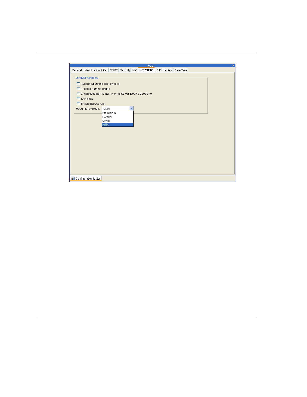
Chapter 4: Redundancy
Figure
4-6 – Networking Tab AC-1040 – NetXplorer Configuration
8. Click Save. The system will reboot
After rebooting, you can view the changes from the Configuration tab.
For more information concerning NetEnforcer configuration via NetXplorer, see the
NetXplorer Operation Guide.
4-12
NetEnforcer AC-1000 Hardware Guide

Chapter 4: Redundancy
Parallel Redundancy
Failure of a network device can be catastrophic, causing network downtime and lost
business. The key to designing any mission-critical network is to recognize that these
failures can occur, and to design a network that can handle failures and still allow the
network to function. In order to do this, it is important to use the most reliable
equipment, with redundancy built in to all mission-critical equipment.
A NetEnforcer can operate in parallel to provide Parallel Redundancy. Parallel
Redundancy requires two NetEnforcer systems and, where an external Bypass Unit is
used, a single Bypass Unit.
The Primary NetEnforcer handles the traffic and the Secondary NetEnforcer is designed
to stand by as long as the Primary NetEnforcer is active. Only if, for any reason, the
Primary NetEnforcer is not able to function properly does the Secondary NetEnforcer
become active.
Both NetEnforcers receive traffic from the internal network, but only the Primary
NetEnforcer is passing the traffic to the external network.
While the Primary NetEnforcer receives and handles traffic coming from the external
network, the Secondary External interface is disabled, since the system is in Standby
mode. If the Primary NetEnforcer should fail, the Secondary NetEnforcer automatically
takes control of the traffic, and enables its External interface.
In Parallel Redundancy mode, Bypass mode is activated in the unlikely event that both
the Primary and Secondary NetEnforcers fail.
NetEnforcer AC-1000 Hardware Guide
4-13

Chapter 4: Redundancy
Status Indicators in Parallel Redundancy Mode
When operating in Parallel Redundancy mode, two NetEnforcer units are connected.
During operation, the LED indicators on NetEnforcer give various readings. The LEDs
relevant to operations in Parallel Redundancy mode are the Standby, Active and Power
LEDs on the NetEnforcer LCD panel.
The modes of operation of the indicators are described in the following tables:
Standby
LED
Primary
Unit
Secondary
Unit
Primary
Unit
Secondary
Unit
Primary
Unit
Secondary
Unit
Primary
Unit
Secondary
Unit
OFF ON ON Primary NetEnforcer is in Active mode.
ON OFF ON Secondary NetEnforcer is ready to take
OFF OFF ON Primary NetEnforcer fails or is now
OFF ON ON Secondary NetEnforcer took over and
OFF OFF OFF Primary NetEnforcer is powered OFF.
OFF ON ON Secondary NetEnforcer took over and
OFF ON ON Primary NetEnforcer is in Active mode.
OFF OFF OFF Secondary NetEnforcer is powered
Active
LED
Power
LED
Analysis
over.
booting.
is in Active mode.
is in Active mode.
OFF. The only Fail-safe mode available
now is Bypass.
4-14
NetEnforcer AC-1000 Hardware Guide

Chapter 4: Redundancy
Standby
LED
Primary
Unit
Secondary
Unit
Table 4-1 – LED Conditions: AC-1000 Series, Parallel Redundancy Mode
OFF OFF ON Primary NetEnforcer failed or not
OFF OFF ON Secondary NetEnforcer failed or not
Active
LED
Power
LED
Analysis
completed booting.
completed booting. Bypass is activated
(in the primary unit and all traffic is
going through Bypass.
Secondary NetEnforcer Activation
When two NetEnforcers are connected in Parallel Redundancy mode, the Secondary
NetEnforcer will take control and become the active unit under the following
conditions:
• Upon a Primary subsystem failure.
• During booting of the Primary NetEnforcer platform. When booting is
completed, the Primary unit automatically takes control again.
• Upon any Primary NetEnforcer power feed failure and power OFF condition.
• Upon the Primary NetEnforcer Ethernet cable disconnecting from either the
Internal or External ports. After reconnecting the cable and rebooting, the
Primary NetEnforcer takes control again.
• When the Bypass Unit is not connected properly to the NetEnforcer Backup
connector, even with all other connectors fully plugged.
NOTE If a cable is disconnected, it is recommended to reboot the Primary
NetEnforcer after reconnecting the cable.
NetEnforcer AC-1000 Hardware Guide
4-15

Chapter 4: Redundancy
To connect two AC-1000 Series NetEnforcers in Parallel Redundancy:
Before using NetEnforcers in Parallel Redundancy mode, make sure that the
configuration of both NetEnforcers is identical; except for their IP addresses, which
must be unique for each unit.
After ensuring identical configuration, test each NetEnforcer (while connected to the
network as a single device) and verify that they are operating identically to one another.
1. Configure redundancy in both NetEnforcers as outlined in Enabling Redundancy
on p. 4-1.
2. Designate one of your NetEnforcers to be the default Primary, and connect the
end of the Backup cable to the Backup connector of the NetEnforcer.
3. Connect the other end of the backup cable to the Primary connector of the Bypass
Unit.
4. Designate the other NetEnforcer to be the Secondary and connect one end of the
Backup cable to the Backup connector of the Secondary NetEnforcer.
5. Connect the other end of the Backup cable to the Secondary connector of the
Bypass Unit.
6. Ensure that the status indicators of both systems are indicating that the systems
are configured correctly, as follows:
• The Active LED of the Primary NetEnforcer is ON.
• The Standby LED of the Primary NetEnforcer is OFF.
• The Active LED of the Secondary NetEnforcer is OFF.
• The Standby LED of the Secondary NetEnforcer is ON.
CAUTION When two NetEnforcers are connected in Redundancy mode with a
switch on each interface, if the Primary NetEnforcer fails and the
Secondary system takes control of traffic, the redundant unit may
take some time to activate. This is normal switch behavior. The
switch will continue to redirect packets to the Primary NetEnforcer,
instead of to the Secondary NetEnforcer.
4-16
NetEnforcer AC-1000 Hardware Guide

Chapter 4: Redundancy
Active Redundancy
NOTE Active Redundancy is only relevant to AC-1020 and AC-1040 units. The
AC-1010 does not support Active Redundancy.
In an Active Redundancy configuration, each NetEnforcer manages a single link while
duplicating the link’s traffic to the other NetEnforcer. Both NetEnforcers are active.
Each unit shapes the traffic of one link only, but the shaping algorithm considers traffic
of both links. Such configuration is recommended for network topologies where both
links are active in load-balancing mode.
Failover
In the event that one of the links fails due to router, switch or line malfunction, the
network redundancy mechanism (for example, spanning tree) will ensure that traffic is
routed or switched via the other link and managed by the second NetEnforcer. Since
both NetEnforcers maintain a constant view of the two links, there will be no loss of
flow's state and other information required for correct shaping and application
classification. Note that the bypass function is not used in such configurations.
Policy Configuration
In the Active Redundancy configuration, the two NetEnforcers should share the same
policy configuration.
NetEnforcer AC-1000 Hardware Guide
4-17

Chapter 4: Redundancy
Connecting the NetEnforcer in Active Redundancy
Line 1 (and 3 in the AC-1040) is used to pass actual traffic – these interfaces will be
used to connect the NetEnforcers to the corresponding switches or routers.
Line 2 (and 4 in the AC-1040) is used to duplicate traffic and pass it to the second
NetEnforcer. Traffic that is passed between NetEnforcers is not sent to adjacent network
devices – it is only used for monitoring and classification purposes.
Active Redundancy for the AC-1020
In this configuration the operator uses two links to access the Internet. To achieve
redundancy, each link will use a separate switch and router. Each link requires an AC1020 unit and a bypass unit to enable Active Redundancy.
Each link has a similar structure. The switch port is connected to the Internal port of the
first line card’s bypass unit. The corresponding port is connected to the Internal port of
the AC-1020. The External port of the AC-1020 is connected to the external port of the
bypass unit while its corresponding port connects to the router. The other ports of the
bypass unit remain unconnected. The two AC-1020 cross-connect one to another with
two links to enable synchronization of traffic between the two units.
Active Redundancy for the AC-1040
This configuration is suitable for a high-availability fully meshed environment, where
operators use two switches and two routers to connect their networks to the Internet.
Each switch connects to the two routers to provide redundancy.
In this scenario, two AC-1040 units are installed together with two bypass units.
• The two AC-1040 units cross-connect one to another with four links to
synchronize the traffic information between themselves.
• Each AC-1040 unit connects via its corresponding bypass unit to the two
switches (via two internal interfaces) and to a router (via two external interfaces).
• The remaining interfaces of the bypass units remain unconnected.
4-18
NetEnforcer AC-1000 Hardware Guide

Chapter 4: Redundancy
Serial Redundancy
In Serial Redundancy two bypass units are connected to the network in serial and the
two NetEnforcers work in Active/Bypass mode.
One probe is in active mode at all times, and the other is in bypass mode. There is no
probe is standby mode. When the active probe moves to bypass, the passive probe
switches to active.
Even if the previously active probe recovers, it will remain in bypass. The system will
not try to converge to a pre-determined configuration, as it does in parallel redundancy
In a normal situation the Primary Bypass forwards all traffic to the Primary
NetEnforcer’s which is in Active mode.
Figure
NetEnforcer AC-1000 Hardware Guide
4-7 – Serial Redundancy – Normal Scenario
4-19

Chapter 4: Redundancy
NetEnforcer Failover
In case the Primary NetEnforcer fails, the unit will go in to bypass mode forwarding all
traffic directly to the network bypassing the failed NetEnforcer. The Secondary
NetEnforcer will go in to active mode forwarding all traffic via the secondary unit.
NetEnforcer functionality will be maintained.
In the unlikely situation where the Secondary unit fails, it will go in to bypass mode
bypassing the failed NetEnforcer. Network connectivity will maintain but all
NetEnforcer functionality will be lost.
Bypass unit is provided with each NetEnforcer units. In case of failover situation
(including power-loss), the links connected to the bypass will be wired (cross
connected) and traffic will not be disturbed. The bypass unit is a passive device and
does not require external power supply.
Figure
4-20
NetEnforcer AC-1000 Hardware Guide
4-8 – Serial Redundancy – Failover Scenario

Chapter 4: Redundancy
Figure
4-9 – Serial Redundancy – Bypass Scenario
Serial Redundancy in Mesh Topologies
Serial Redundancy can support mesh topology configurations. In the network diagram
described below, each of the NetEnforcer units should be able to handle two links
which requires it to have four network interfaces. The AC-1020 can be used in such a
configuration.
NetEnforcer AC-1000 Hardware Guide
4-21

Chapter 4: Redundancy
Figure
4-10 – Serial Redundancy – Mesh Scenario
In a network configuration with four network interfaces, each of the NetEnforcer units
must have eight network interfaces. The AC-1040 can be used in such a configuration
4-22
NetEnforcer AC-1000 Hardware Guide

Chapter 5: Hardware Specifications
Dimensions
Standard 2U by 19-inch, rack mountable
Height
Width
Depth
Weight
NOTE The weight of the Copper Bypass Unit is 3.86 lbs (1.75 kg) and the weight
of the Fiber Bypass Unit is 4.28 lbs (1.94 kg).
3.46 in (88 mm)
17.32 in (440 mm)
14.76 in (375 mm)
Copper: 24.9 lbs (11.3 kg)
Fiber: 25.3 lbs (11.48 kg)
Power Requirements
AC Power Input Voltage
Frequency
Current
DC Power Input Voltage
Current
100 - 240 V
50/60 Hz
2 - 1 A
48 - 60 V
6 - 4 A
NetEnforcer AC-1000 Hardware Guide
5-1

Chapter 5: Hardware Specifications
Operating Environment
Temperature
Humidity
32° F to 104° F (0° to 40° C)
5% to 95% (non condensing)
5-2
NetEnforcer AC-1000 Hardware Guide

Chapter 5: Hardware Specifications
Standards, Compliance and Certifications
EMC
EMC Directive 89/336/EEC, article 7(1)
EN 55022:1998+A1(00) class A
EN 61000-3-2:1995_A1(98)+A2(98)
EN 61000-3-3:1995
EN 55024:1998+A1(01)
FCC 47 CFR part 15, subpart B, class A
ICES-003:1997, class A
VCCI:2002, class B
NEBS: GR-1089-Core*
Safety
IEC 60950:1999 with Japanese deviations
EN 60950:2000
NEBS: GR-1089-Core*
UL
1950 NetEnforcer UL File number: E206586
CAN/CSA C22.2 No.60950-00 * UL 60950, third edition
Environmental
ETS 300 019-2-2 T 2.1
ETS 300 019-2-3 T 3.1
NEBS: GR-63-Core*
*NetEnforcer is designed to meet these standards.
NetEnforcer AC-1000 Hardware Guide
5-3


Chapter 6: Firewall Port Reference
In some networks, the NetEnforcer can be separated from the NetXplorer server by a
firewall for security reasons.
To enable the communication between the NetXplorer and NetEnforcers the following
ports in the Firewall should be opened:
• TCP/80 HTTP
• UDP/161 SNMP
• UDP/162 SNMP Trap
• UDP/123 NTP
• TCP/123 NTP
NetEnforcer AC-1000 Hardware Guide
6-1


Chapter 7: Équipement de série AC-1000
Le NetEnforcer est une passerelle d’apprentissage transparente certifiée conforme à la
norme IEEE 802.1, fonctionnant parallèlement à une unité de dérivation en vue
d’assurer la continuité du débit de données en cas de problème matériel ou logiciel. La
dérivation du NetEnforcer redirige l’ensemble du trafic uniquement vers des éléments
passifs, permettant ainsi au réseau de fonctionner.
Le NetEnforcer de série AC-1000 associe une conception de classe transporteur à une
redondance des éléments fondamentaux afin de garantir la continuité du fonctionnement
du système en cas de panne, avec notamment des ventilateurs particulièrement
performants et une double-alimentation commutable à chaud. Cette série a été
développée dans l’objectif de répondre aux exigences des normes ETSI.
Les mises en garde et remarques suivantes doivent faire l’objet d’une attention toute
particulière:
NetEnforcer AC-1000 Hardware Guide
7-1

Chapter 7: Équipement de série AC-1000
Mises en garde d’ordre général:
CONFIGURATION Afin de garantir une continuité de service en cas de panne,
l’ensemble des modèles de la série AC-1000 fonctionne uniquement
en raccordement avec une unité de dérivation adaptée.
LASER
PRODUIT LASER DE CLASSE 1. DANGER !
Rayonnement laser invisible en cas d’ouverture.
ÉVITER TOUTE EXPOSITION DIRECTE AU
FAISCEAU.
ALIMENTATION Les modules d’alimentation en entrée (option d’alimentation c.a.)
sont dotés de deux fusibles (T2A 250 V, 5 x 20 mm) à chaque point
d’accès. L’un d’eux est uniquement fourni en tant qu’élément de
rechange pouvant remplacer à tout moment le fusible principal en
cas de nécessité (opération réalisée au niveau du boîtier de
fusibles). Pour garantir une protection continue contre les
incendies, toujours remplacer un élément par un composant du
même type et de même intensité.
Avant de retirer le couvercle, déconnecter le produit de
l’alimentation secteur. Toute opération de réglage et d’entretien
réalisée au niveau du dispositif doit uniquement être effectuée par
un personnel qualifiée, avec l’appareil déconnecté de sa source
d’alimentation.
ALIMENTATION C.C. La source d’alimentation c.c. doit être protégée contre les
surintensités par un circuit de dérivation affichant une intensité
nominale de 10 A, basé dans le bâtiment et capable de déconnecter
simultanément les deux pôles.
CÂBLE D’ALIMENTATION
C.C.
7-2
NetEnforcer AC-1000 Hardware Guide
Mise à la masse de l’unité c.c. : Avant de raccorder le produit à une
ligne d’alimentation, s’assurer que la borne de masse de protection
du dispositif est reliée au conducteur de masse de sécurité du
cordon d’alimentation secteur.
La prise mâle secteur doit uniquement être insérée dans une prise

Chapter 7: Équipement de série AC-1000
femelle connectée à la masse. Cette mesure de protection ne doit
pas être contrecarrée par l’utilisation d’une rallonge non munie
d’un conducteur de protection (relié à la masse).
Toute interruption du conducteur de protection (relié à la masse)
ou toute déconnection de la borne de masse de protection pourrait
compromettre la sécurité du dispositif. Toute interruption
volontaire est strictement interdite.
Dans cette gamme d’appareils, le conducteur relié à la masse du
circuit d’alimentation c.c. est raccordé au conducteur de masse.
DÉRIVATION Afin de garantir la continuité du service en cas de panne, toute
unité NetEnforcer AC-1000 doit être reliée à une unité de
dérivation adaptée.
Redondance Dans le cas d’une connexion en mode redondant de deux dispositifs
NetEnforcers à un commutateur sur chaque interface, l’unité
redondante pourrait mettre un certain temps à reprendre le
contrôle du trafic si le dispositif primaire venait à présenter une
défaillance et que le dispositif secondaire prenait le contrôle du
trafic. Il s’agit-là d’un comportement tout à fait normal de la part
du commutateur, qui continuera à rediriger les paquets de données
vers le distributeur primaire, plutôt que vers le dispositif
NetEnforcer secondaire.
NetEnforcer AC-1000 Hardware Guide
7-3

Chapter 7: Équipement de série AC-1000
Remarques d’ordre général:
LASER Dans le cas d’un produit doté d’un émetteur-récepteur en fibre optique, les
émissions dégagées par les produits décrits dans ce guide sont de Catégorie
1, conformément aux normes IEC 60825-1 et FDA 21 CFR 1040.10 / 1040.1.
Ces produits ne doivent en aucun cas être installés dans un réseau optique
traitant des émissions de classe supérieure à 1.
Paramétrage Il est déconseillé de modifier les paramètres par défaut du NetEnforcer ; la
modification des paramètres NIC s’effectue uniquement par le biais du
panneau ACL.
L’alimentation c.a. s’adapte automatiquement à des tensions comprises
entre 100 et 240 V, à une fréquence de 50/60 Hz. L’alimentation c.c., quant à
elle, s’adapte automatiquement à des tensions de 48 ou 60 V c.c.
Cet équipement est destiné à une utilisation dans un espace à accès limité et
par un personnel dûment qualifié. Pour éviter tout choc électrique, ne
réaliser aucune opération autre que celles décrites dans le feuillet
d’instructions de déballage.
Alimentation Pour supprimer un module d’alimentation, dévisser les deux vis figurant
dans les coins inférieurs droit et gauche, soulever la poignée et extraire le
module.
Câbles
Ethernet en cuivre
Câbles
Ethernet en fibre
optique
7-4
NetEnforcer AC-1000 Hardware Guide
À l’aide des câbles Ethernet droits UTP CAT-6 fournis, raccorder les
connexions de lien portant les étiquettes Internal (Interne) et External
(Externe). La longueur maximale de ces câbles est généralement de 50
mètres.
À l’aide de câbles en fibre optique de 62.5/125μ ou 9/125μ dotés de
connecteurs LC doubles (non fournis), raccorder les ports 1 Gbps du
commutateur au routeur.

Chapter 7: Équipement de série AC-1000
Spécifications matérielles
Dimensions
Conception 2U standard de 19 pouces, montable en rack
Hauteur 88 mm (3.46 in.)
Largeur 440 mm (17.32 in.)
Profondeur 375 mm (14.76 in.)
Poids Cuivre: 11,3 kg (24.9 lbs)
Fibre optique: 11,48 kg (25.3 lbs)
REMARQUE L’unité de dérivation en cuivre pèse 1,75 kg (3.86 lbs) ; celle en fibre optique
pèse 1,94 kg (4.28 lbs).
Spécifications requises
Alimentation
Tension c.a. en entrée 100 - 240 V
Fréquence 50/60 Hz
Intensité 2 - 1 A
Tension c.c. en entrée 48 - 60 V
Intensité 6 - 4 A
Conditions ambiantes
Température 0 à 40 °C (32 à 104° F)
Humidité 5 à 95 % (sans condensation)
NetEnforcer AC-1000 Hardware Guide
7-5
 Loading...