

Page 1
ALLNIC AUDIO
L-9000 OTL/OCL LINE-STAGE PREAMPLIFIER
OWNER’S MANUAL
Page 2

ALLNIC AUDIO
L-9000 OTL/OCL LINE-STAGE PREAMPLIFIER
Thank you for purchasing the Allnic Audio L-9000 OTL/OCL (Output TransformerLess/Output Capacitor-Less) Line-Stage Preamplifier. We are certain your trust in Allnic
Audio and its dealers worldwide, as well as your appreciation for the sound of this
high-quality device, will be rewarded by its excellent operation for years to come.
Please read this entire manual before you connect the L-9000 OTL/OCL Line-Stage
Preamplifier to the other components of your system and the wall outlet.
*** Information and specifications for the Allnic Audio product described in this
manual are subject to change without notice.
*** For a list of Allnic Audio distributers around the world, please visit Allnic
Audio’s website:
http://allnicaudio.com
2
Page 3

TABLE OF CONTENTS:
INTRODUCING THE L-9000 OTL/OCL LINE-STAGE
PREAMPLIFIER
4
WHAT’S IN THE BOX?
6
SAFETY
6
CLEANING
Chassis
Connectors
7
INITIAL SET-UP
Location, Location, Location
Power Connection
Inputs
Outputs
Remote Control
7
8
8
8
8
INITIAL POWER ON
9
OPERATION
10
CURRENT METERS
11
TUBES
11
SPECIFICATIONS
12
WARRANTY
13
FIGURES
14
Please read about SAFETY before you attempt to use the L-9000 OTL/OCL
Line-Stage Preamplifier - we care about our customers and the
equipment, and we want you to enjoy this product for a long time!
3
Page 4

INTRODUCING THE L-9000 OTL/OCL LINE-STAGE PREAMPLIFIER
Immerse yourself in the original recorded space. The L-9000 OTL/OCL (Output TransformerLess/Output Capacitor-Less) is a triple gain stage, remote controlled, line-stage preamplifier,
without transformers or capacitors in its single-ended signal path. It uses the 6080 double
triode as its directly coupled output power tubes; i.e., there are no output transformers on the
single-ended (unbalanced) RCA outputs, so the 6080s communicate the signal directly to the
connected power amplifier or amplifiers, fully revealing the 6080s’ inherent accuracy and
beauty.
In common circuits, output capacitors or output transformers are required to separate the AC
music signal from the DC operating potential. If this is not done, the latter will destroy the
power amplifier, the loudspeakers, or both. However, these two coupling devices also
introduce their own influences on the transmission of the musical signal, adding their own
character (colouration), increasing distortion, and consuming small signals, all as predicted by
physical efficiency theory. In addition, they also limit signal dynamics. For these reasons, the
elimination of output transformers and capacitors has been considered the best solution for
the design of the most accurate amplifiers. Removal of these two coupling devices from the
signal path achieves the best results possible:
• No colouration of the musical signal
• Extremely detailed expression, natural harmonics and subtle musical decay
• The lowest possible distortion
• The widest musical dynamics
In the L-9000, there is no coupling device between the preamplifier and the power amplifier;
that is, the final gain/output tubes are directly connected to the power amplifier. Thus, the
benefits listed above are fully present in the Allnic L-9000 preamplifier.
Some circuit experts might be concerned about DC potential in the music signal in an OTL/OCL
design. However, the chance of this problem occurring can be essentially and reliably 100%
mitigated. To do this, Allnic uses a “floating power supply circuit”, a design that deals with the
issue by not creating any DC potential in the first place, or such a small potential that it is
harmless.
The L-9000’s OTL/OCL circuit is basically SEPP, “Single-Ended, Push-Pull”, so a “cancellation
circuit” is required to adjust the balance of signal between the upper and lower power output
tubes’ input grids. Allnic uses an extremely sophisticated “Active Balanced Positive and
Negative Feedback Circuit”, in which the 6AN8 pentode perfectly controls the circuit’s
operation with extremely low distortion and incredible speed.
The L-9000 OTL/OCL is a world-class, reference level, line-stage preamplifier. It offers
unbelievably realistic, holographic sound-staging combined with incredible resolution, clarity,
micro-dynamics, and drive. Instrument and vocal tones and timbres are breathtakingly lifelike,
4
Page 5
and the placement of instruments and bodies in three dimensions startling, life-size, and
addictive. The L-9000 OTL/OCL has no voice of its own, none. It is silent, except for the music
emanating from the blackest of backgrounds. In addition, the stunningly realistic sonic quality is
matched by the simple elegance, flexibility and ergonomic functionality of the L-9000’s
casework and connection options. The L-9000 sits between the L-10000, Allnic Audio’s top
OTL/OCL line-stage preamplifier, and the L-8500 OTL/OCL line-stage preamplifier.
The L-9000 OTL/OCL has the following features:
• Pure single-ended, Class A operation
•
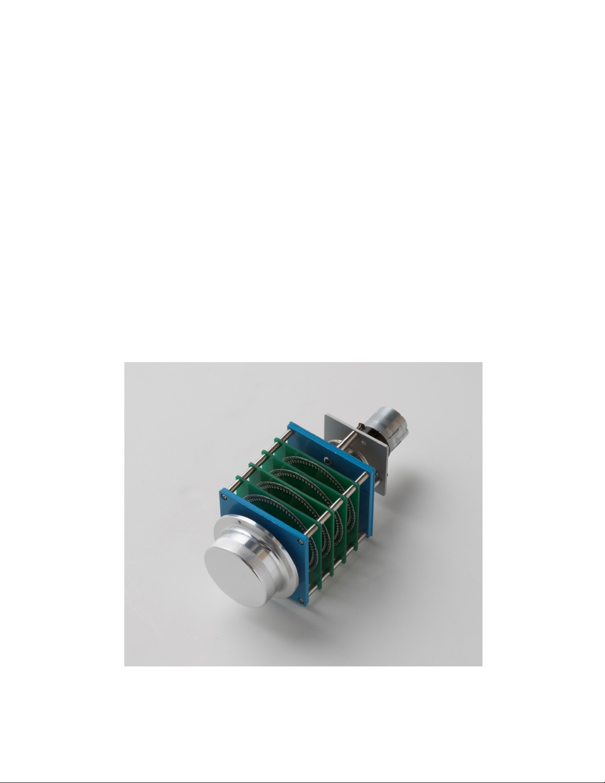
61 STEP CONSTANT IMPEDANCE BRIDGED TYPE ATTENUATOR - A world’s “first of its kind”
for Allnic Audio
The L-9000 OTL/OCL does not employ a digital IC volume control or a low-cost carbon film
volume control with a motor. The L-9000 OTL/OCL uses the WORLD’S FIRST 61 step, constant
impedance, “bridged” type attenuator. Allnic’s new attenuator is now the most sophisticated
on the market, and we believe, without a doubt, also the absolute best sounding. With fixed
impedance and no (± 0db) channel imbalance at any volume level, this revolutionary and
currently unique, oil clutched, motorized attenuator will astound users with its elevation of
the fidelity and purity of any system in which it finds a home.
The Allnic 61 step constant impedance bridged type attenuator
5
Page 6

•
Minimal negative feedback
•
For its balanced (XLR) outputs, permalloy transformers, like those used in Allnic’s transformer-
coupled preamplifiers, are employed.
•
As are all Allnic Audio products, the L-9000 OTL/OCL is fully RoHS (EU Reduction of Hazardous
Substances regulation) compliant in construction and materials.
WHAT’S IN THE BOX?
Please check that the shipping box contains the following:
• One (1) Allnic L-9000 OTL/OCL Preamplifier – in natural aluminum or black, depending on your
order specification
• One (1) power cord
• One (1) remote control
• Two (2) x AAA batteries for the remote control
• One (1) Owner’s Manual
Note:
1) The L-9000 OTL/OCL ships with the tubes installed.
2) The L-9000 OTL/OCL will work with most IEC type aftermarket power cords. The Allnic ZL-
3000 and ZL-5000 power cables will make an excellent match. Of course, only you can
determine the power cord that works most synergistically with the L-9000 OTL/OCL in your
system.
3) Be sure the L-9000 OTL/OCL is labeled for the AC voltage of your location. If it is not, DO
NOT connect it to your AC outlet. Please contact your Allnic dealer.
We advise that you keep the box and other packing materials that your L-9000 OTL/OCL came in. It
will be useful if you sell your L-9000 OTL/OCL or in the unlikely event you need to ship it for
service.
SAFETY
• CAREFULLY and SLOWLY remove ALL cardboard and Styrofoam cushioning material inside
the tube chimneys before operation.
• Disconnect the power cord by pulling the plug, not the cable.
• Keep the power cord away from any heat source.
• Keep the unit away from liquids – do not allow any liquid to enter the interior of the unit.
• When the unit is moved from a cold to a warm environment, allow sufficient time for any
condensation to evaporate before plugging the unit into an AC connection.
• Do not attempt any repairs.
6
Page 7

• Do not remove the chassis cover without specific authorization from your Allnic dealer.
• See the notes on “Location, Location, Location”.
CLEANING
A. Chassis and glass
Use only a soft, lint-free cloth dampened slightly with water only (NO cleaning fluids!) to clean the
faceplate, meter glass and chassis.
B. Connectors
You may use any good quality contact cleaner recommended for such applications to clean the
contacts from time to time as you deem appropriate.
INITIAL SET-UP
A. LOCATION, LOCATION, LOCATION
Like all audio products using tubes, the Allnic Audio L-9000 OTL/OCL needs to be placed on a solid
stand in a location that provides for good air circulation around the preamplifier.
• DO NOT cover the top of the preamplifier.
• DO NOT place the unit on carpet or foam.
• DO NOT subject the unit to knocks and shocks as you move it around. This advice is meant
particularly for those who may want to place the L-9000 OTL/OCL on a set of after-market
isolation feet or similar devices. Dropping one side of the L-9000 OTL/OCL, or the whole unit,
is not a good thing.
• DO NOT place the unit near a strong light or heat source.
• DO NOT place anything heavy on the unit.
• DO NOT allow rubber or vinyl materials to rest on the unit’s chassis for long periods of time.
This could discolour the metal.
• DO place the unit on a shelf or stand that is stable and not subject to vibration or sudden
shock.
• DO consider using a high quality power cord and interconnects, both inputs and outputs. The
L-9000 OTL/OCL is a highly sensitive piece of electronic equipment designed for neutrality and
will output what you put into it. Allnic’s Zero Loss Technology power cables and MU metal
shielded interconnects will work synergistically with the L-9000 OTL/OCL.
• DO try to place the L-9000 OTL/OCL away from major sources of RFI and EMI; though well
shielded, the L-9000 OTL/OCL will function best away from large power transformers and
other sources of such interference.
7
Page 8

B. POWER CONNECTION
The L-9000 OTL/OCL uses a standard three prong male 15 amp IEC connection for AC input. You
need to use a power cord with a female three prong 15 amp IEC connector at one end.
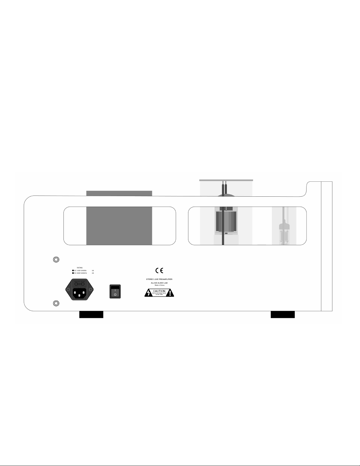
To the left of the IEC connector (facing the left side of the unit as in Figure 1), there is a power onoff switch. Leave this switch in the OFF position – that means the switch is pressed “down” at the
bottom - while you make all initial connections.
The L-9000 OTL/OCL you have purchased is set internally for AC 110/120 volt – 60 HZ, or 220/230
volt – 50 Hz operation. There is no way to change this to another AC setting without return of the
unit to the factory for re-wiring, at the owner’s cost, including transport both directions.
C. INPUTS
There are five (5) inputs. Line 1 and Line 2 are balanced connections (XLR type connectors). The
remaining three (3) line inputs are RCA type, single-ended connections. None of the inputs is
intended especially for connection to any particular device.
NO PHONO STAGE - The L-9000 OTL/OCL is a line-stage preamplifier and does NOT have a built-in
phono preamplifier section. You will need a phono preamplifier if you want to use a turntable with
the L-9000 OTL/OCL. You can connect your phono preamplifier to any of the five inputs, provided
you have the appropriate types of connections or adaptors.
The L-9000 OTL/OCL has been designed and manufactured to work most synergistically with
Allnic Audio phono preamplifiers, pre-preamplifiers, equalization and power amplification
products, and ZL Technology cables.
D. OUTPUTS
The L-9000 OTL/OCL has three pairs of outputs. One (1) pair is single-ended unbalanced, using RCA
type connectors; two (2) output pairs are balanced (i.e., separate ground), using XLR connectors
(see Figure 2). Only the RCA, unbalanced connectors are directly coupled to the 6080 output stage,
so only the RCA outputs are "pure" OTL/OCL. The balanced XLR output connectors are coupled to
a pair of permalloy output transformers. We recommend trying both as you might prefer one over
the other.
You may use the balanced and single-ended RCA outputs at the same time; for example, if you run
one pair to your stereo amplifier and the other pair, or pairs, to a powered subwoofer or a pair of
them.
E. REMOTE CONTROL
The remote control provides the ability to remotely:
8
Page 9

• Select the line source input using either the numbered selector buttons (1 to 5) or the channel
up/down arrow buttons (see Figure 3).
• Control the volume level using the right (louder) and left (quieter) arrow buttons adjacent to
the channel arrow buttons.
• Mute the volume using the button labeled “MUTE”. To raise the volume again after muting,
press the Mute button to take the volume level to where it was prior to muting. In Mute
mode, the light above the “operate” button on the front panel of the L-9000 OTL/OCL will not
be illuminated; it will illuminate when the L-9000 OTL/OCL is unmuted again.
• Use the red power on/off button in the top left-hand corner of the remote control to power
the L-9000 OTL/OCL on and off.
INITIAL POWER-ON
Once you have your L-9000 OTL/OCL in place and all connections have been made to your sources
and amplifier(s) and the power cord is installed and plugged into an AC receptacle, you are ready
to turn on the power for your L-9000 OTL/OCL. Before you power up the L-9000 OTL/OCL, though,
be sure you have:
•
CAREFULLY AND SLOWLY removed ALL the cardboard cushion materials from inside the
tube chimneys
•
ensured all tubes are snugly in their sockets
•
ensured the batteries are in the remote control – if not, insert the batteries (by removing
plate on the bottom of the remote control)
•
turned the volume down on, or muted the L-9000 OTL/OCL
•
checked that all your connections are snug
Also, be sure you have manually turned the volume control on the front panel to the extreme
counter-clockwise position (minimum volume).
Push the power on-off switch to the left of the IEC connector (facing the left side of the unit as in
Figure 1) so it is in the “on position”. That will power up the L-9000 OTL/OCL. From this point on,
you need only use the far left hand button marked “power” on the front panel or the power
button on the remote control to turn the L-9000 OTL/OCL on and off.
Once the power has been turned on, the following will happen on the front panel (Please see
Figure 4):
• the light above the “power” button will illuminate
• the meters on the front panel will illuminate
• the light over the line source button that is depressed will illuminate
• after about 40 seconds, the light over the “operate” button will illuminate. The L-9000
OTL/OCL has a “soft start” delay for the tubes in order to extend tube life.
9
Page 10

FINAL/3rd GAIN STAGE BALANCING USING THE CURRENT METERS
There is one current meter for each channel on the front of the L-9000 (See Figure 4). These
meters indicate the potential for DC from the output of the third gain stage tubes in the L-9000
OTL/OCL, the 6080s.
The needles of the meters should be between 10 o’clock and 2 o’clock. However, because of the
floating power supply circuit, even if a needle falls to the extreme left or right of a meter, there is
no danger to the connected amplifier or speakers because any possible DC leakage will be so small
it cannot do any damage; in fact, it can hardly even be measured.
Initially, and from time to time as may be necessary (this should be very infrequently, if ever, for
example, when replacing a 6080 tube), the meters are used to roughly balance the 6080 third gain
stage tubes for DC control in both channels.
Using a small, flat blade screwdriver, turn the screw head located immediately above each of the
meters on the L-9000’s face (see Figure 4) clockwise and counter-clockwise until the needles of
both meters are between 10 o’clock and 2 o’clock. It is not necessary for the needles to be
between the two lines in the centre of the meter. It is also not necessary for the meters to be
exactly in exactly the same location; anywhere between 10 o’clock and 2 o’clock is fine.
Please be patient; it could take some time to get an approximate balance, but once set, it should
rarely, if ever, move.
The Allnic Audio L-9000 OTL/OCL is now ready for operation. At this point, you can power on your
sources and, finally, your stereo power amplifier or mono-blocks.
OPERATION
From this point on, operation is straight-forward. All functions are controlled from the front panel
or the remote control. Of course, BE CAREFUL about differences in gain between your sources.
Generally, disc players and tuners will have greater gain than phono stages. That means the
volume setting for listening to your turntable might be too high for listening to digital disks or
streaming devices.
To avoid surges to the speakers, it is best to change from input to input only with the “operate”
button set to mute (the light above the button will not be illuminated when the button is in the
“mute” position).
When you are finished listening, turn off your stereo power amplifier or mono-block amplifiers.
Then turn off the L-9000 OTL/OCL by depressing the power button on the front panel. The power
switch on the left side panel should stay in the “on” position – this will keep key circuitry warm,
and your L-9000 OTL/OCL will be ready to play when the soft-start turns on the L-9000 OTL/OCL
next time you want to listen. Turn off your sources last.
10
Page 11

CURRENT METERS
As previously noted, there is one current meter for each channel on the front of the L-9000 (See
Figure 4). These meters indicate the potential for DC from the output of the third gain stage tubes,
the 6080s. The needles of the meters should be between 10 o’clock and 2 o’clock. However,
because of the floating power supply circuit, even if a needle falls to the extreme left or right of a
meter, there is no danger to the connected amplifier or speakers because any possible DC leakage
will be so small it cannot do damage; in fact, it can hardly even be measured. The variations in
readings are due to the characteristics of individual tubes; no two tubes are exactly alike in every
way.
If a needle falls to the extreme left or right of the meter, try switching the 6080 tube of the
channel showing the drop for the one in the other channel. If that still does not rectify the
situation, one or both of the 6080 tubes may need to be replaced.
Within the tube warranty period, if any 6080 tube is outside spec as described above, please
contact your Allnic dealer or other authorized Allnic representative for assistance. Outside the
tube warranty period, Allnic Audio and its authorized representatives are still available to consult
for advice.
TUBES
The L-9000 OTL/OCL uses the following tubes (see Figure 5):
• Two (2) x 6U8A
• Two (2) x 12AU7
• Two (2) x 6080
All consequences of changing or attempting to change tubes are borne by the user unless by
express agreement between the owner and Allnic Audio or its authorized representative. Allnic
Audio and its authorized representatives are not liable in any way whatsoever for any injury or loss
incurred by the user or for damage to the L-9000 OTL/OCL, any of its parts, or tubes or
replacement tubes resulting from the user changing or attempting to change tubes.
11
Page 12

SPECIFICATIONS
• Inputs:
Line level × 5 pairs:
Balanced (XLR) × 2
Unbalanced (RCA) × 3
• Outputs:
3 pairs:
Unbalanced (RCA) × 1 pair
Balanced (XLR) × 2 pair
• Input
Impedance:
10kΩ Balanced/Unbalanced
• Frequency
Range:
5Hz to 100kHz
• Voltage Gain:
+18dB
• THD (1kHz):
Less than 0.03% (1kHz, 1V RMS)
• S/N Ratio:
-100dB (CCIR, 1kHz)
• Maximum
Output:
20V RMS (Non-clipping)
• Output
Impedance:
90Ω
• Power
Consumption:
120W at 110/120V (60 Hz)
120W at 220/230V (50 Hz)
• Tubes:
6U8A (no equivalent) x 2 (first gain
stage)
12AU7 (equivalent to ECC82, ECC802, B749,
CV491, CV4003, 5814, 5963, 6189, 6350, 6680,
7316, 7730) × 2 (second gain stage)
6080 (some equivalents – contact
your dealer for recommendations)
x 2 (third gain stage)
• Fuse:
3A/120V; 3A/230V
slow blow
FOR THE ALLNIC AUDIO L-9000 OTL/OCL LINE-STAGE PREAMPLIFIER
12
Page 13

• Tube chimney
screws:
2mm Allen head
• Dimensions:
430mm (16.95 inches) (W)
400mm (15.75 inches) including handles (D)
180mm (7.1 inches) (H)
• Weight:
22 kg (48.4 lbs) unpacked.
27 kg. (59.5 lbs) packed in original
shipping material
WARRANTY
FOR WARRANTY SERVICE, PLEASE CONTACT YOUR AUTHORIZED ALLNIC DEALER.
All Allnic Audio amplifier products are warranted against materials and manufacturing defects for
parts, excluding tubes, and labour for two (2) years from date of purchase. Tubes are warranted
against materials and manufacturing defects for one (1) year from date of purchase. The warranty is
transferable for the balance of the original purchaser’s warranty period, provided, as stated below,
no unauthorized repairs or modifications have been performed on the product. Date of purchase is
the date indicated on the invoice for the product issued by Allnic Audio or its authorized
representative. For the warranty to be valid, a defective product must be returned to Allnic Audio’s
authorized representative for service prior to any unauthorized attempt to repair. Any repair work on
an Allnic Audio product not specifically authorized by Allnic Audio or its authorized representative will
void the warranty on the product.
13
Page 14
FIGURES
Figure 1 – L-9000 OTL/OCL Left Side Panel View
14
Page 15
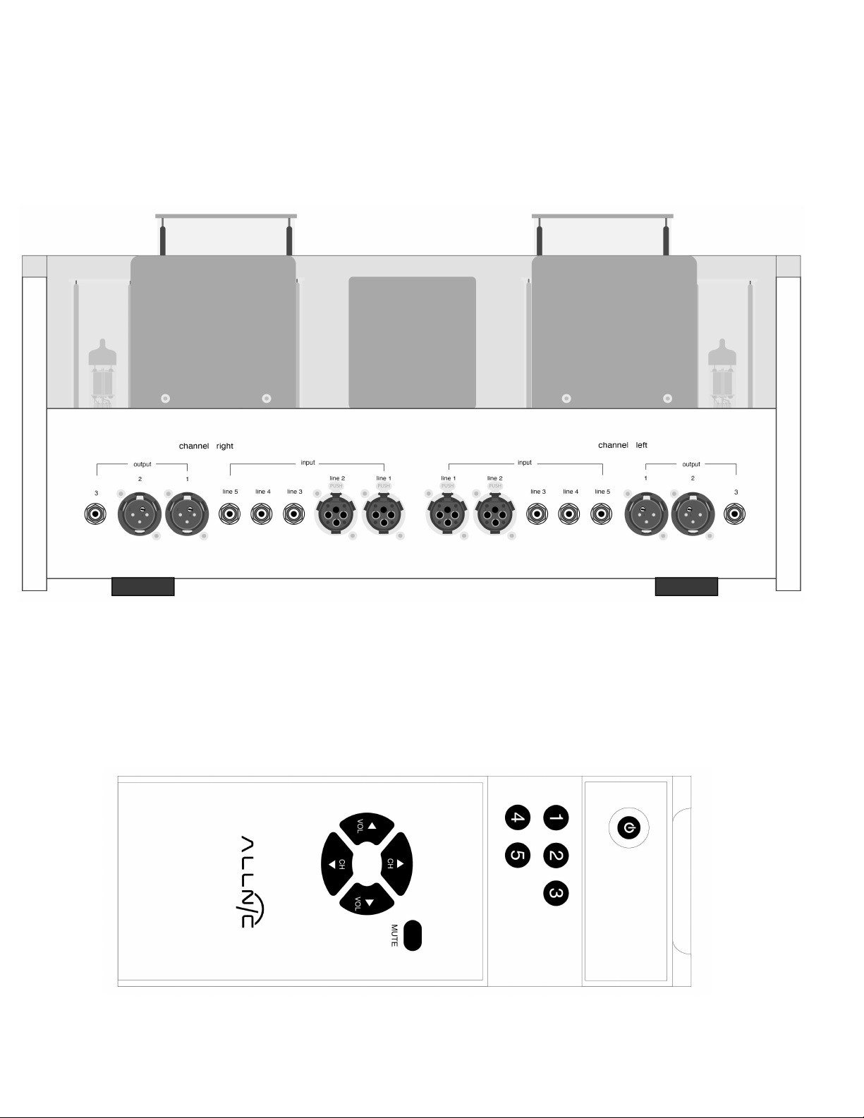
Figure 2 – L-9000 OTL/OCL Rear Panel View
Figure 3 – L-9000 OTL/OCL Remote Control
15
Page 16
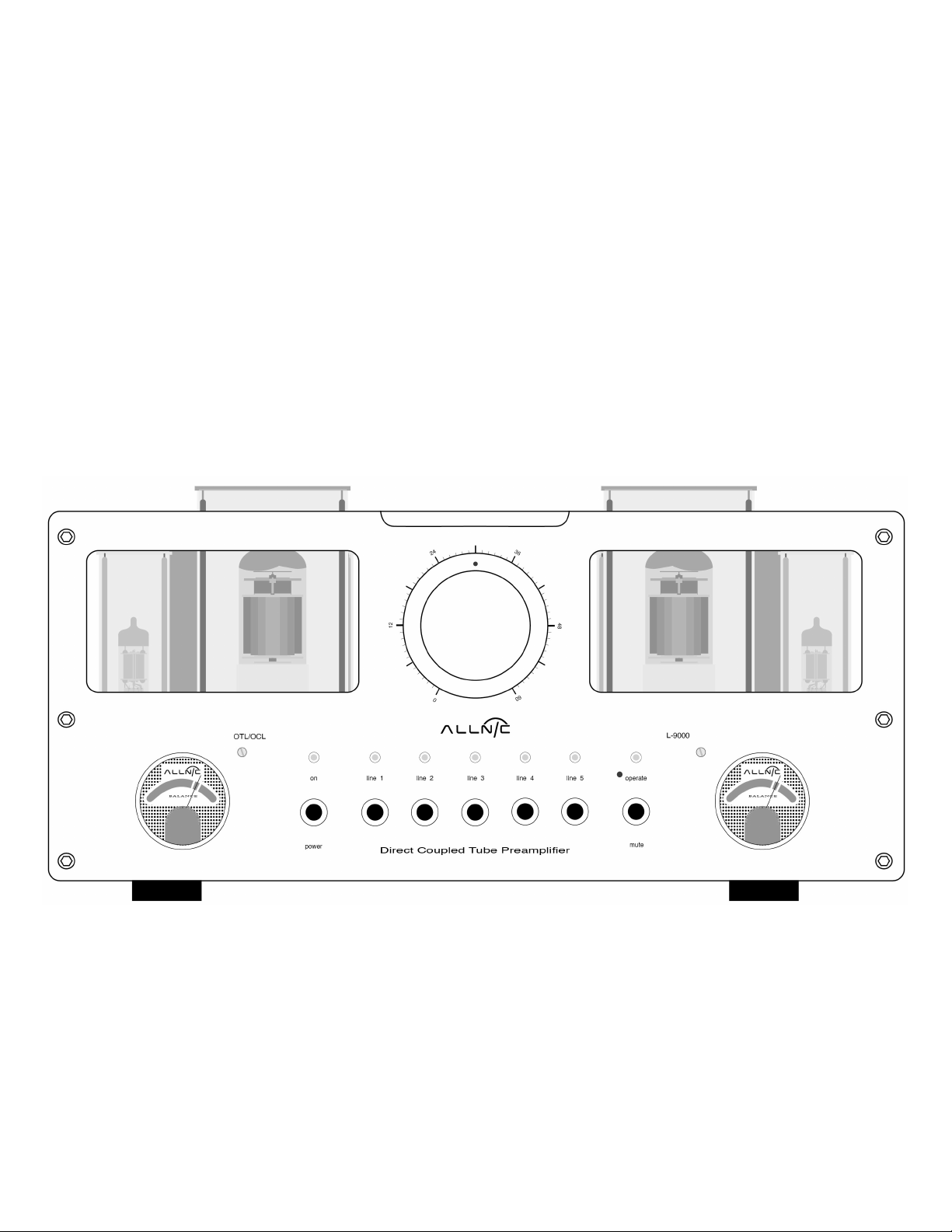
Figure 4 – L-9000 OTL/OCL Front Panel View
16
Page 17
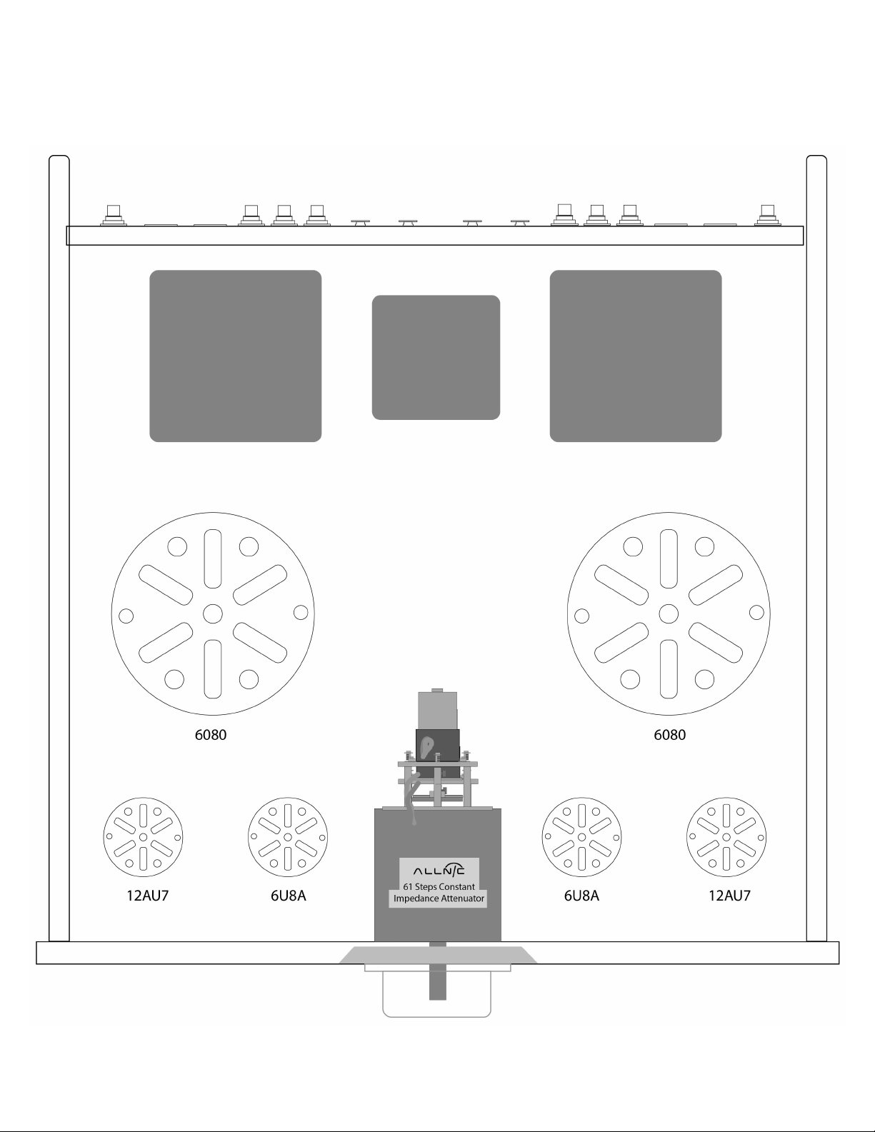
Figure 5 – L-9000 OTL/OCL Top View
17
 Loading...